EP0054071B1 - Einrichtung zur sicherung von dokumenten gegen fälschung und verfahren und vorrichtung zu seiner herstellung sowie deren verwendung - Google Patents
Einrichtung zur sicherung von dokumenten gegen fälschung und verfahren und vorrichtung zu seiner herstellung sowie deren verwendung Download PDFInfo
- Publication number
- EP0054071B1 EP0054071B1 EP81901976A EP81901976A EP0054071B1 EP 0054071 B1 EP0054071 B1 EP 0054071B1 EP 81901976 A EP81901976 A EP 81901976A EP 81901976 A EP81901976 A EP 81901976A EP 0054071 B1 EP0054071 B1 EP 0054071B1
- Authority
- EP
- European Patent Office
- Prior art keywords
- sheet
- data
- authenticator
- translucency
- characteristic
- Prior art date
- Legal status (The legal status is an assumption and is not a legal conclusion. Google has not performed a legal analysis and makes no representation as to the accuracy of the status listed.)
- Expired
Links
Images


Classifications
-
- G—PHYSICS
- G06—COMPUTING OR CALCULATING; COUNTING
- G06K—GRAPHICAL DATA READING; PRESENTATION OF DATA; RECORD CARRIERS; HANDLING RECORD CARRIERS
- G06K19/00—Record carriers for use with machines and with at least a part designed to carry digital markings
- G06K19/06—Record carriers for use with machines and with at least a part designed to carry digital markings characterised by the kind of the digital marking, e.g. shape, nature, code
- G06K19/08—Record carriers for use with machines and with at least a part designed to carry digital markings characterised by the kind of the digital marking, e.g. shape, nature, code using markings of different kinds or more than one marking of the same kind in the same record carrier, e.g. one marking being sensed by optical and the other by magnetic means
- G06K19/083—Constructional details
- G06K19/086—Constructional details with markings consisting of randomly placed or oriented elements, the randomness of the elements being useable for generating a unique identifying signature of the record carrier, e.g. randomly placed magnetic fibers or magnetic particles in the body of a credit card
-
- G—PHYSICS
- G06—COMPUTING OR CALCULATING; COUNTING
- G06K—GRAPHICAL DATA READING; PRESENTATION OF DATA; RECORD CARRIERS; HANDLING RECORD CARRIERS
- G06K19/00—Record carriers for use with machines and with at least a part designed to carry digital markings
- G06K19/06—Record carriers for use with machines and with at least a part designed to carry digital markings characterised by the kind of the digital marking, e.g. shape, nature, code
- G06K19/08—Record carriers for use with machines and with at least a part designed to carry digital markings characterised by the kind of the digital marking, e.g. shape, nature, code using markings of different kinds or more than one marking of the same kind in the same record carrier, e.g. one marking being sensed by optical and the other by magnetic means
- G06K19/10—Record carriers for use with machines and with at least a part designed to carry digital markings characterised by the kind of the digital marking, e.g. shape, nature, code using markings of different kinds or more than one marking of the same kind in the same record carrier, e.g. one marking being sensed by optical and the other by magnetic means at least one kind of marking being used for authentication, e.g. of credit or identity cards
-
- G—PHYSICS
- G07—CHECKING-DEVICES
- G07F—COIN-FREED OR LIKE APPARATUS
- G07F7/00—Mechanisms actuated by objects other than coins to free or to actuate vending, hiring, coin or paper currency dispensing or refunding apparatus
- G07F7/08—Mechanisms actuated by objects other than coins to free or to actuate vending, hiring, coin or paper currency dispensing or refunding apparatus by coded identity card or credit card or other personal identification means
- G07F7/086—Mechanisms actuated by objects other than coins to free or to actuate vending, hiring, coin or paper currency dispensing or refunding apparatus by coded identity card or credit card or other personal identification means by passive credit-cards adapted therefor, e.g. constructive particularities to avoid counterfeiting, e.g. by inclusion of a physical or chemical security-layer
Definitions
- the invention relates to an authenticator device according to the preamble of claim 1 and it also relates to methods and apparatus for the production and use of such an authenticator device.
- the system of the present invention may be variously implemented to authenticate a wide range of subjects, including people.
- the random characteristic over an area of a sheet relied upon for verifying the authenticity is constituted by an area of the device having included therein magnetic fibres. These magnetic fibres are specifically incorporated into the device during the production thereof for the purpose of making possible the verification process.
- the device then is sensed with the aid of a sensing apparatus which is capable of revealing for each individual sensed location the presence or the absence of a magnetic fibres.
- the result of this sensing then is recorded on the authenticator device itself in an encoded manner.
- the checking apparatus first reads out from the device the recording which has been made in accordance with the foregoing; the checking apparatus then repeats the sensing of the specific locations with respect to the presence or absence of magnetic fibres, whereupon the original sensing result and the check-up sensing result are compared for verifying authenticity.
- an authenticator device of this known type may be useful in connection with several applications there are nevertheless applications where a higher information density of the authenticator device and also a better economy of producing the authenticator device is desired.
- translucency characteristics inherent to the sheets of medium usually used for authenticator devices can be relied upon as the primary authentication characteristics in connection with the desired verification of the authenticity and that such translucency characteristics do not necessitate any additional effort when producing the devices but nevertheless provide an increased information density.
- the presence or absence of magnetic fibres or blackened areas (DE-AS 2847756) at specific location of an authenticator device merely provides two different values (presence or absence) a characteristic feature constituted by translucency renders possible varying degrees of characteristics which nevertheless are easily measurable. Also these various degrees of characteristics then can be reliably recorded on the authenticator device in encoded form and relied upon for the verification process.
- the present invention relies on a characteristic as is inherent in the usual composition of the medium.
- the considerable expense which is involved by adding foreign substances, applying intricate printing patterns or even using intermediate layers of business instruments for applying specific authentication features can easily be avoided according to the present invention.
- business instruments like labels for clothing pieces like jeans, or identity cards or commercial papers often are needed in very large quantities where the additional expense involved by any artificially applied authentication feature may constitute an unacceptable contribution to the manufacturing costs.
- FR-PS 2,229,099 has disclosed the idea of recording on an instrument to be automatically read information arranged in such a way as to command, when the document is read, the selection of the information present on the document which is to be read.
- this prior art reference discloses the feature of automatically positioning a document using position data on the document.
- the authenticator device as characterized in claim 1 is clearly distinguished from all the prior art in that it is of simple design with attendant economy and reliability.
- Claim 10 characterizes a preferred method of producing an authenticator device as claimed in the preceding claims.
- Claims 11, 12, and 13 relate to further advantageous developments and improvements of such method.
- Claim 14 relates to an advantageous method for verification of an authenticator according to any of the claims set out above.
- Claims 15 and 16 relate to a preferred apparatus for producing authenticators according to the claims stated above.
- Claims 17-20 relate to an advantageous apparatus for verifying authenticators according to the above-stated claims.
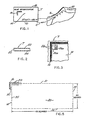
- a shoe S is fragmentarily represented along with an authenticator tag T which is securely attached to the shoe by a cord C.
- the tag T carries a legend in the form of a reference number 10 which may be duplicated in the shoe, e.g. number 12.
- the system of the present invention enables authentication of the tag T to verify that the shoe S is a genuine article.
- the tag T is identified with the shoe S by the similar numbers 10 and 12.
- the number 10 indicates and specifies a measurable but not practicably duplicable physical characteristic of the tag T.
- a field of locations (array of squares) which has a characteristic measurable, but not practicably duplicable pattern of variations in translucency.
- the location of that pattern and its form are defined by a representative number that is cryptographically related to the identical numbers 10 and 12. That is, a pattern of locations in the space 14 and their translucency are coded into the reference number 10.
- the tag T (if authentic) verifies the genuine nature of the particular shoe S only because the identification numbers 10 and 12 coincide.
- the medium of the space 14 may be integrated in the actual product that is to be identified, or other codes can be employed.
- a marginal area of the sheet of paper bearing the print may serve to provide the pattern of measurable but not duplicable random variations.
- other characteristics can be utilized.
- a specific tag T may be employed only to identify a single article. That is, while the tag T might be affixed to a fake duplicate of the shoe S, such a switch to the counterfeit shoe would leave the genuine shoe S without an authenticator thereby presumably reducing its value.
- the tag T might be completely blank or could carry only an indication of the coded locations.
- the pattern locations could be uniform and the information on the characteristic pattern could be kept on an inventory or list of specific products or objects. Comparing a freshly sensed characteristic pattern with the recorded characteristic pattern would then authenticate a product.
- Such implementations could be desirable for items of limited production or large monetary value, e.g., graphic art prints.
- the space 14 simply appears as a blank area that is located by a corner indicia 16.
- Several predetermined small secret areas (perhaps different on each authenticatortag) in the space 14 have measured translucencies.
- Such a set of translucency values is coded in the reference number 10. That is, the encoded number 10 indicates the locations of the small secret areas and their translucency values.
- the number 10 also includes certain miscellaneous data, e.g. coding data, a date, codes used, a product serial or batch number, and so on.
- the tag T usually will also carry a trademark or other identification indicia 18.
- the space 14 may be enhanced as disclosed below with printing, to visually appear as an image, design or pattern so long as the measurable but not duplicable characteristic (random in the manufacture) is preserved.
- the tag T comprises a sheet 20 of bond paper laminated between a pair of protective clear layers 22 and 24.
- a durable and stable tag T with a plane reference surface is the result.
- Locating such areas involves first locating the space 14, defining the field of locations therein, then finding the specific locations of interest.
- the corner indicia 16 locates the space 14 and is shown substantially enlarged in Figure 5.
- areas 26 are represented to suggest the varying translucency of the paper in the tag T.
- the area 26a is represented to contain a considerable quantity of somewhat opaque fiber with the consequence that it would produce a low numerical indication of translucency, e.g. perhaps "one” or "two” on a scale of "zero" through. "nine".
- the area 26b is indicated to be relatively clear of light-obstructing fibers or particles and as a consequence would be relatively translucent, perhaps producing a representative value of "eight" or "nine".
- the values produced from the other defined areas in the space 14 would lie in the range of these extremes.
- the small-area translucency characteristic is measurable but not duplicable in a commercially practicable way, as a result of its small and complex pattern form.
- the measurable but not duplicable pattern will also be characterized as being random.
- the random character occurs in the growth, development or manufacture of the medium and is not simply random data imposed on the medium.
- the phenomenon occurs commonly in fibrous material, as in bond paper.
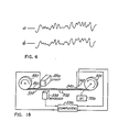
- One technique for sensing the areas 26 of the tag T involves scanning a line or row of the areas 26 continuously to produce an analog signal that can then be sampled at periodic intervals. Specifically, for one heavy paper, a scansion of translucency along a row of the areas 26 resulted in an analog signal as represented in Figure 4a. Subsequently, another scansion taken along the same row of areas 26 resulted in an analog signal as illustrated in Figure 4b. Thus, it may be seen that the values are repeatable so that a record of the curve of Figure 4a may be checked with the curve of Figure 4b (recently sensed) to verify the identification of the medium. As suggested above, the actual comparison may involve digitized samples of the signals at discrete intervals. Detailed forms of such comparison means are disclosed below.
- the location of the array 28 is displaced from the corner indicia 16 by an offset distance (varying for different authenticators) indicated by a line 30.
- the location of the array 28 in relation to the corner indicia 16 is specified by one decimal digit of the reference number 10.
- the array 28 defines a matrix or grid of nine hundred and sixty of the individual squares 29. Specifically, the array 28 ( Figure 5) is twenty squares from top 31 to bottom 33 and forty-eight squares from left edge 35 to right edge 37. Consequently, the grid contains nine hundred and sixty squares 29 which are numerically designated square "000" to square "959". Again, it is to be understood that neither the array 28 nor the individual squares are visually indicated on the tag T in any manner. Rather, their format and their precise locations are defined in relation to the indicia 16 by the reference number 10 and the operating format of the system. Essentially, time and motion relationships are used to locate the spaces.
- the array 28 is divided into eight separate rectangular sectors as graphically illustrated in Figure 6. Specifically, the sectors A, B, C, D, A', B', C', and D' occupy the array 28 in a rectangular pattern, and each sector contains one hundred and twenty of the squares 29 ( Figure 5).
- the squares within each of the sectors ( Figure 6) are also in a rectangular pattern and are designated as follows:
- the code or reference identification for each tag T is derived from the array 28 ( Figure 5) by selecting one square from each of six sectors A, B, C, D, A', B', C', or D' ( Figure 6).
- the measurable but not duplicable characteristic observed in the physical medium of the tag T at each of the selected squares 29 ( Figure 5) provides a representative signal on a scale from zero to nine.
- six such representative signals are developed as a characteristic code to identify the tag T.
- test apparatus can verify the tag.
- the six decimal digits of the characteristic code are embodied in the decimal reference number 10 ( Figure 1) which is printed on the tag T.
- the specific data format of the printed reference number is as follows:
- the reference number 10 in a format in accordance with the above table is used in a signal represented form, identified as a code word PN.
- code word PN the first sixteen digits (decoded word DW including words SD, AN, and CC above) are cryptographically coded into a code word designated CW. Consequently, the code word CW may not identify directly with the digits of the decoded word DW, although the data of each include: one digit indicative of the offset or location of the array 28, nine digits which indicate the six predetermined locations or addresses of the selected squares in the array pattern, and six digits indicative of the translucency at the selected squares.
- the coded word CW (sixteen digits) is supplemented by an additional ten digits (word IW) to complete the data of the code word PN.
- word IW additional ten digits
- decimal digits will be used in the following explanations, recognizing that implementations may be in a form of binary-coded decimal or pure binary codes.
- the code word PN is developed on the basis of randomly selected location data and measurements of the tag T.
- the selected data measures the offset of the array 28 ( Figure 5) and the locations of the specific squares 29 therein that are to be used to specify the characteristic.
- the measurements of those squares 29 provide six additional digits (word CC).
- the word PN is completed with miscellaneous data as indicated above and reduced to the form of the reference number 10 which is printed on the authenticator tag T.
- the tag T is then available for authentication to verify the likelihood that an associated product is genuine without reference to other memory. Thus, it is not necessary in this implementation to store inventories of tag characteristic data separate from the tags themselves.
- the authentication system of this embodiment cryptographically decodes a portion of number 10 (code word CW) to provide the decoded word DW. That word indicates: the precise location of the observed pattern of squares 29 in the array 28 ( Figure 5) and the digits indicative of the previously observed value of the physical characteristic at each of such individual squares.
- the system After determining the location pattern of the select squares 29, the system senses the physical characteristic values of the squares in the form of decimal digits (code word CC') which are then compared with the originally sensed data word CC, six decimal digits. As disclosed in detail below, the comparisons are performed in a manner to allow some tolerance for situations in which the tag T may have been damaged or changed with age. Also, various other techniques can be used in that regard, as to set a scale based on a current measurement or observation.
- the array 28 ( Figure 5) is divided into eight sectors ( Figure 6), each of which is in turn subdivided into one hundred twenty squares 29.
- the system encodes the authenticator tag T by sensing six predetermined squares 29 from the array 28 of nine hundred and sixty squares. Those six select squares 29 provide six decimal digits. Note that the six decimal digits are taken from six different sectors and are addressed by nine decimal digits. Such addressing is accomplished by obtaining (randomly or selectively) the addresses forthree squares (nine decimal digits) in the sectors A, B, C, or D then mathematically deriving related addresses for the sectors A', B', C', or D'. Thus, in case of damage to an authenticator, addresses often can be derived from remaining valid data.
- the sector A contains a uniform sub-array (ten by twelve) of one hundred and twenty of the squares 29 designated or addressed by the numerals 000 through 119. Consequently, a three-digit decimal number from 000 through 119 (inclusive) designates a specific square in sector A. By incrementing the address by 600 the same numerical address also designates a particular square in sector A' (sequence 600-719). As a specific example, the number 075 designates a specific square in the sector A and as a related value, the number 675 designates a square in sector A'.
- Square designations in sector B are incremented by 360 to obtain an address for designating a square in sector B'.
- Addresses designating squares in sector C are incremented by 600 to designate squares in sector C'.
- addresses for squares in sector D are incremented by 360 to be translated into addresses for squares in the sector D'.
- an address word of nine decimal digits indicates six squares in the array 28.
- nine decimal digits indicate three squares in three of the four sectors A, B, C, or D and three squares similarly in three of the four sectors A', B', C', or D'.
- the division or partitioning as suggested above is regular and uniform. That is, the squares 29 in each sector lie in a rectangular array of rows and columns. Specifically, for example, the right-most column (vertical) of sector A ( Figure 6) contains squares addressed by the numerals zero through nine. Such a format is used to subdivide each of the sectors of the array 28.
- the array 28 is sensed or observed by a bank of twenty miniature photoelectric cells which are aligned with the coinciding rows in pairs of side-by-side sectors.
- the squares 29 of the sectors A and B are read together as the bank of cells relatively scans across the space 28. If using an authenticator made of standard data processing card stock, squares of one-tenth of an inch are effective with a tolerance to fifteen thousandths of an inch.
- a random code generator 50 provides code words which are screened or verified as specifying appropriate offset and address.
- the code generator 50 provides signals representative of the nine-digit word AN to a register 52 along with a single digit SD, indicative of the offset of the array 28 from the corner indicia 16 ( Figure 5). This operation occurs during a period indicated by a timing signal ta as represented in Figure 7.
- a timing signal ta as represented in Figure 7.
- the binary timing signal ta along with similar subsequent timing signals tb and tc can be provided by various digital structures, as a counter.
- the representative number of decimal digits for registers in the system of Figure 7 are indicated in parentheses at each register.
- the timing signal tb sees the offset digit SD applied to an MBND (measurable but not practicably duplicable) physical characteristic sensor 54 along with the address word AN.
- the sensor 54 receives an authenticator, e.g. tag T, and under the command of the representative signals SD and AN locates six squares 29 on the tag T at which translucency is sensed to provide the six-digit characteristic code word CC.
- an alternative to selective sensing would be to sense or read the entire array 28 to provide an analog signal, then selectively gate portions of that signal as related by time and space to the select six squares 29.
- the digits of the code word CC are represented by six decimal digits designated U, V, W, X, Y, and Z. These digits along with the offset digit SD and the address word AN are placed in a register 56 during the interval of the timing signal tc.
- a form of cryptographic encoder 58 receives the contents of the register 56 (sixteen digits of the word DW) for cryptographic encoding to provide the coded word CW for the printed reference number 10.
- the digits of the word CW are supplied to a register 60 which also receives the miscellaneous data portion or code word IW from a register 62. In that fashion, the register 60 receives the reference number PN which, in one operating format, is imprinted on the tag T ( Figure 1).
- the register 60 may incorporate a readout device for providing the reference number 10 (representative of word PN).
- the signals representative of the number may be employed to drive any of a variety of printing mechanisms to imprint the identification number on the tag authenticators T. If desired, as indicated above, the identification number may also be placed on the article or product for sale (number 12, Figure 1).
- the PN register 60 may be connected to a magnetic recorder 64 for recording the number PN on the authenticator it identifies, the authenticator incorporating a magnetic recording surface as disclosed in detail below.
- a system of continuous operation for producing complete authenticators also is described below.
- an authenticator e.g. tag T ( Figure 1) is associated with an article, e.g. the shoe S, in due course the occasion may arise to verify the authenticity.
- verification is performed by reading the number 10 (word PN) and decoding it to obtain: (1) the locations of squares 29 in the space 14 which are to be sensed (word AN) and (2) the values of the characteristic expected to be sensed at the indicated squares (word CC).
- word PN the array 28 is defined
- Figure 6 the identified squares ( Figure 6) are sensed.
- the resulting fresh numerical observations (word CC') then are compared with the similar previous recorded observations (word CC) to confirm authenticity.
- the tag T ( Figure 1) is placed in an authenticator holder 66 which is associated with a numerical input device 68 and a sensor 70.
- the device 68 inputs the reference number 10 ( Figure 1-twenty-five digits) providing representative electrical signals for that number.
- the device 68 may comprise any of a wide variety of structures ranging from a manual key-operated apparatus to a numerical optical reader. If the reference number 10 is in the form of a bar code, the device 68 may be a wand or other type of bar-code scanning device, such as those employing laser scanning, as known in the art.
- the input device 68 includes a magnetic stripe reader.
- the device 68 functions during an interval designated by an initial binary timing signal ta to load a register 72 with a code word PN representative of the number 10 ( Figure 1).
- Signal representations from the register 72 (comprising the code word CW) are applied to a cryptographic decoder 74 which function during an interval of a timing signal tb to develop the decoded word DW, signal representations for which are placed in a register 76 during the interval of the timing signal tc.
- the sixteen digits of the word DW are allocated as follows: the first digit SD designates the offset (line 30, Figure 5); the following nine digits, designated word AN, specify the addresses of the squares 29 to be sensed; and the last six digits, word CC, specify the characteristic code and comprise the digits U, V, W, X, Y, and Z.
- the sensor 70 receives signals representative of the digit SD along with the signal represented word AN. As described above, the signals specify six squares 29 of the authenticator. At such locations, the tag T is sensed to provide signals representative of six decimal digits U', V', W', X', Y', and Z' as indicated above.
- the signals representative of such digits (word CC') are supplied from the sensor 70 to a comparator 78 which also receives signals representative of the corresponding digits U, V, W, X, Y, and Z (word CC) from the register 76. That is, during the interval of the signal td, the comparator 78 receives the code word CC which was carried in the identification number PN, concurrently with the freshly sensed code word CC'.
- the comparator 78 provides signals to indicate the degree of coincidence between those two code words. Specifically, the comparator 78 supplies a signal to a display apparatus 80 which may indicate any one of the numerals: "0", “1", “2”, and "3". Exhibition of the numeral "0” indicates no significant degree of comparison thereby designating the tag T as a fraud. Display of the numeral "1” indicates a small degree of coincidence, e.g. two of the six digits may compare. In a related fashion, the display of numeral "2" indicates a greater degree of comparison, and the numeral "3" indicates full coincidence. Thus, the observer is afforded with an indication of the degree of coincidence; and in that regard, some latitude may be tolerable or desirable as part of an acceptable authentication. As indicated above, the display 80 may also manifest various data as the product batch number or even a specific product number. In that manner, the system of the present invention is useful in detecting diversion of products as well as the counterfeiting of products.
- the cryptographic code may range from being a relatively simple one, requiring only manual decoding, to a complex one requiring computer decoding with a randomly generated computer key stored in the computer, and unknown to any living person.
- the material of the authenticator and its environment may permit use to a standard of complete coincidence.
- considerable tolerance may be advisable to allow for damage to a portion of the authenticator.
- tests on various fibrous materials including paper tag or label stock indicate a wide variety of media that meet the requirement of being repeatably scannable, preservable, and unique with regard to the translucency patterns discussed above.
- a three-digit comparison may be accomplished by using either half of the tag. That is, as the digits U, V, and W are derived from three of the four sectors A, B, C, or D and the digits X, Y, and Z are derived from three of the four sectors A', B', C', and D', one set of three values may be obtained upon ignoring either half of the authenticator as shown in Figure 6. If the lower half of the array 28 is ignored, the sectors A', B, C', and D remain intact. If the right half of the array 28 should be lost, the sectors A, B, C, and D remain intact; and so on.
- the system of Figure 9 is illustrated for use with an authenticator 102 (upper right) in the form of a tag or card as described above.
- the authenticator 102 is sensed or scanned while it is moved by a mechanical apparatus incorporated in a transport and pulse generator 104.
- the generator 104 is connected as illustrated to roller pairs 106 and 108 which move the authenticator 102 from right to left in relation to devices for dynamic sensing. Traveling from the roller pair 106 through the roller pair 108, the authenticator 102 passes through four sensors or readers.
- the authenticator 102 first passes under an optical reader 110 which senses the reference number 10 from the authenticator in the form of the word PN comprising twenty-six decimal digits. With the sensing of the number 10, the authenticator moves under a sensor 109 for a light analyzer 111.
- the analyzer tests the authenticator 102 spectrographically, to indicate material foreign to that of which the authenticators are made.
- the authenticator moves under a line sensor 112 that detects the corner indicia 16 ( Figure 1). the line sensor 112 senses the point from which clock pulses are counted for determining the offset.
- the authenticator 102 is then moved under the characteristic translucency sensor 114 for scanning. It is to be noted that zero offset could always be used, as in a continuous motion system of operation.
- the characteristic sensor 114 incorporates a bank 116 of miniature photoelectric cells that are illuminated by an opposed light source 118. It is perhaps noteworthy that tests with various media indicate that in certain instances it may be desirable to use colored light (narrow spectrum bands). Specifically, blue light was found to be very effective for sensing the translucency of certain card stocks. Furthermore, the translucency of some card stocks or paper media may vary in spectral response to the point that colored light may be used to invoke another test element. That is, for example, a record of translucency measurements at one or more specified locations, using two or more different light sources for each location can provide another criterion in the verification of the authenticator.
- the authenticator 102 passes between the bank 116 and the light source 118, it is scanned along twenty parallel rows, to provide twenty signals, each of which is representative of the translucency (perhaps with regard to light of a specific color) of a row of squares defined on the authenticator 102.
- the characteristic sensor 114 provides the analog translucency signals to output lines 120 which are connected to signal processors 122 for amplifying and refining the individual analog signals before application to a series of selector gates 124.
- the gates 124 pass discrete samples of the observed analog signals which are representative of the selected squares 29 defined on the authenticator 102.
- the gates 124 are controlled by address information and clock signals C as described in greater detail below.
- the card transport and pulse generator 104 supplies timing signals and clock signals to the gates 124 indicative of the instant position of the authenticator 102 as it moves under the characteristic sensor 114.
- signals from the reader 110 representative of the code word PN are first set in the register 126 for further processing.
- One portion of the word PN i.e. the cryptographically encoded word CW, comprises the first sixteen digits of the word PN.
- the remaining portion of the word PN (word IW consisting of ten digits) is not cryptographically encoded and simply indicates miscellaneous information or data, e.g. the date of encoding, an identification of the cryptographic encoding technique used, product information, and the like.
- Signals representative of the code word IW are supplied from the register 126 to a display unit 128 for direct display illustrated as "data" in Figure 8.
- the cryptographically encoded word CW is supplied from the register 126 to a cryptographic decoder 130.
- the sixteen coded digits are decoded to provide the code word DW which is then set in a register 132 (center right).
- the word DW consists of three parts, specifically: (1) the digit SD indicating the shift or offset of the array 28 from the corner indicia 16 ( Figure 1); (2) the address information word AN for locating the predetermined squares; and (3) the translucency data word CC for the translucency of the preselected squares.
- the six-digit word CC is conveyed by signals from the register 132 to a compiler 134.
- the compiler 134 formulates the following combinations of the reference digits for comparison, the coincidence of any one of which with freshly sensed information affords an indication that the authenticator 102 is genuine; specifically:
- the analog signals are supplied through the electrical lines 120 ( Figure 9, upper left) and the signal processors 122 to the selector gates 124.
- Two control signals (clock and gating) are provided to the gates 124 to pass selected samples of the analog signals during six discrete intervals.
- Such analog signal samples are selected by the address word AN and indicate the translucency of the six predetermined squares in the array 28 of the authenticator 102.
- the address word AN is manifest by signals that are supplied from the register 132 (central right) to a decoding matrix 140 for the development of control signals that are in turn applied to the gates 124.
- the nine decimal digits of the word AN include three, three-digit numbers to indicate directly three squares or addresses in three of the four sectors A, B, C, or D ( Figure 6). That is, the three, three-digit numbers of the word AN specify a specific row and column for each of the three locations as explained with reference to Figure 6. Additionally, as explained above, the three numbers also specify specific rows and columns in the sectors A', B', C', or D'. Thus, the nine decimal digits are decoded to specify six squares or locations in the array 28 which are to be sensed for translucency.
- Each of the selected squares 29 is selected on the basis of its row and column.
- the designation of a specific row designates a specific one of the lines 120.
- the designation of a specific column specifies a precise period of time during the read process (related to the position of the authenticator 102) which is a sampling interval indicated by timing or clocking signals provided from the transport and generator 104.
- two lines or conductors 142 are provided to carry such signals to an analog-digital converter 144.
- samples could occur simultaneously from adjacent sectors.
- the analog signal samples supplied to the converter 144 are translated into a digital format and supplied through cables 146 to a buffer storage unit 148.
- the freshly sensed code word CC' is developed in a decimal digital format consisting of the digits U', V', W', X', Y', and Z'.
- Those digital signals are supplied from the unit 148 to a register 150 from which signals are supplied to a compiler 152 that is generally similar to the compiler 134. Consequently, the freshly observed translucency code word CC is developed in the compiler 134.
- the signals from the compilers 152 and 134 are sequenced for comparison through the sequencer 136 from which they are applied to a comparator 154. That is, the sequencer 136 incorporates a control 156 which advances a pair of contacts 158 and 160 to synchronously receive the developed composite values of U, V, W, X, Y, and Z.
- a control 156 which advances a pair of contacts 158 and 160 to synchronously receive the developed composite values of U, V, W, X, Y, and Z.
- the comparator 154 incorporates a flip-flop (not shown) which is set in the event of any identical comparisons. Subsequently, that flip-flop produces a signal to illuminate an indicator "OK" of the read-out unit 128. Other coincidences are redundant in such operation.
- the display unit 128 also provides a date and other "data" relating to the authenticator 102.
- the timing signal t1 is applied to the optical reader 110, the light analyzer 111 and the line sensor 112.
- the reference number 10 ( Figure 1) is read to provide signals indicative of the word PN which is registered in the PN register 126.
- the sensor 109 and the light analyzer 111 provides a spectrographic indication, sensing the character of the material of the authenticator 102.
- various degrees of sophistication can be employed in the analyzer 111. If the analyzer 111 determines that the material of the authenticator 102 is improper, a rejection lamp 111A is illuminated indicating negatively on the basis of the spectrographic test.
- the authenticator 102 ( Figure 9) contains to move until the line sensor 112 detects that the corner indicia ( Figure 1) is critically positioned, i.e. in the preparatory position. At that instant, the transport and generator 104 stops the authenticator 102, terminating the initial operating interval designated by a high state for the timing signal t1 and initiating the interval of the timing signal t2.
- the optical reader 110, the light analyzer 111, the line sensor 112, and the register 126 are each operative during the interval of timing signal t1.
- the authenticator 102 is held in a preparatory position pending the time of the binary signal t2 being high, while the word PN is decoded by the decoder 130 to specify the offset as illustrated by the line 30 in Figure 5.
- part of the decoded word AN specifies the squares of interest with data which in turn selects the appropriate signal from the lines 120 and sampling times thereof to provide the correct translucency signals.
- That portion of the word PN which is carried in the sixteen digits designated as word CW is processed by the cryptographic decoder 130 to produce the decoded word DW which is set in the register 132.
- a portion of that word, i.e. the digit SD indicates the offset of line 30 ( Figure 5) and is applied through a digital decoder 133 to the transport and pulse generator 104.
- the single decimal digit SD manifests the predetermined amount of offset. Accordingly, the digit SD is decoded and used by the transport and pulse generator 104 to advance the authenticator 102 a small distance, proportional to the numerical value of the digit SD.
- the timing signal t2 yields to the timing signal t3. Note that all of the timing signals are supplied from the generator 104; however, to preserve the drawing legible, connection lines are not shown.
- the counting of clock pulses determines the initial offset to locate the point where reading begins and that initial operation occurs during the timing signal t3.
- the authenticator 102 is aligned with the characteristic sensor 114 preparatory to the simultaneous or parallel scanning of the rows in the array 28 ( Figure 5). That operation is performed during the timing signal t4 and occurs as the authenticator 102 moves under the bank 116 of sensors.
- analog signals indicative of varying translucency along each of the rows of squares are provided through the lines 120 and the signal processors 122 to be selectively gated to pass six samples to the converter 144. From those analog samples the converter 144 provides six sets of decimal signals to the buffer storage 148 and then to the register 150.
- the timing interval of signal t4 then yields to signal t5.
- the compiler 152 manipulates the digital values as indicated in various combinations of U', V', W', X', Y', and Z'.
- the compilers 152 and 134 each contain a set of combination values. Note that the compiler 134 operates during the period of the timing signal t4.
- the sequencer 136 is operative to sequentially compare the individual combination values from the compilers 134 and 152. In the event of a coincidence at any stage of the comparison, the display 128 is commanded to indicate "OK" at the time of signal t7 manifesting the genuine nature of the authenticator 102. Of course, in the event that no comparison occurs, then the comparator 154 provides a negation signal indicating no authentication. The display 128 supplies a reset signal to the comparator during the interval of timing signal t7.
- Various techniques may be employed to accomplish a statistically satisfactory comprison between fresh and recorded data.
- a sample of the sensed or observed values may be used as a standard which determines the range of other values.
- Such a technique might be employed in systems where the authenticator might change significantly but fairly uniformly with age or exposure to an anticipated environment.
- the signal processors may vary the operating range of the amplifiers (by stretching and clamping) so as to obtain a greater spread or range for the individual signals as well known in the art. In that manner, signal distinction and classification is accommodated.
- the range adjustment may be accomplished at a digital level as well as an analog level; however, for purposes of illustration, reference will now be made to Figure 10 showing a structure which may be incorporated in the signal processors 122 ( Figure 9) to accomplish the variable amplification and to indicate a card that is unreadable.
- Such an unreadable authenticator might be an opaque counterfeit or a genuine card that has been smudged or otherwise ruined.
- the output lines 120 ( Figure 9) from the characteristic sensor 114 are connected to signal processors 122 which as illustrated in Figure 10 may include a plurality of individual amplifiers 201. As indicated, the output from each of the amplifiers 201 is applied to a black-out detector 204 and a range detector circuit 203.
- the detector 204 senses the occurrence of a substantial number of "black" or low level signal outputs indicating a departure from the format standard.
- the detector 203 provides an output range signal indicative of the extreme signals received from the amplifiers 201. Thus, fading or other changes in the authenticator are somewhat compensated, as well as equipment variations.
- the range detector 203 may involve the operation of differential amplifiers to provide a signal which is applied to an amplifier range control circuit 205. Note that both the circuit 203 and the amplifier control 205 are timed to operate during the interval of t3 which affords a preliminary operating interval of the characteristic sensor 114 ( Figure 9) to sense a section of the authenticator that is in advance of the space 28 ( Figure 5). In essence, the authenticator 18 is observed to obtain an indication of the range of variations in translucency. Then, depending upon the observed range, the amplification of the representative signals is accommodated to a desired scale of amplification by the amplifiers 201 ( Figure 10).
- the amplifier range control 205 supplies a signal to each of the amplifiers 201 to shift the scale of amplification.
- the amplifiers 201 are nonlinearly responsive to the signal from the control 205, operating on different portions of an amplification curve to accommodate signal range. An example will illustrate the operation.
- the amplifier range control circuit 205 is set during the interval of the signal t3 and maintains a predetermined control signal for the operation of the amplifiers 201 throughout a sensing operation. Thereafter, during the interval of the signal t7, the control 205 is cleared preparatory to a subsequent cycle of operation.
- the black-out detector senses a situation in which a significant portion of the authenticator has minimal or essentially very low translucency.
- the situation could occur when an authenticator card is dirty or smudged, or as a result of tampering or with the use of a counterfeit card.
- the very low levels of translucency will result in very low levels for the signals in the lines 120.
- the coincidence of a predetermined number of low-level signals in the lines 120 is sensed by the detector 204 to illuminate a lamp 204A.
- Such an event informs an operator that the test may be impossible because of various possibilities as indicated above.
- the illumination of the lamp 204A informs the operator that a card should be carefully inspected in spite of indications by the system, e.g. the authenticator may be a counterfeit or may have been changed to be incapable of verification.
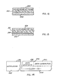
- the card 210 is a laminate article incorporating a basic sheet, e.g. bond paper 215 (see Figures 11,12 and 13), along with certain other media for verification indications.
- a basic sheet e.g. bond paper 215 (see Figures 11,12 and 13)
- the card 210 carries print 212 (upper left) indicating the name of the assigned holder along with a photographic likeness 214 (right).
- the print 212 and the likeness 214 may be variously deposited or printed on a sheet of bond paper 215 ( Figure 12).
- the print 212 and the likeness 214 alter the translucency of the bond paper 215 in certain specific areas. In general, overlays, erasures or other modifications of the print 212 or the likeness 214 will tend to further alter the translucency of the paper 215 at points of alteration.
- the translucency of predetermined areas involving the print 212 or the likeness 214 is sensed and provided as a record for authenticating the card 210. Sensing and recording operations may be as explained above. However, in an alternative arrangement, indications of the translucency are carried on the card in a form that is not generally humanly readable. Specifically, in the authenticator embodiment of Figure 11, the verification confirmation information is recorded on a magnetic stripe 216 which may also provide various other information.
- the magnetic stripe 216 incorporates a clock track which not only indexes another magnetic track of the stripe 216 but additionally indexes non-magnetic areas of the card 210 for critical characteristic observations.
- the characteristic observations include translucency.
- the card 210 might be carried by the assigned holder for identification. An initial confirmation of the holder could be made simply by comparing the likeness 214 on the card with the holder's physical appearance. Confirmation of the card 210 and the absence of modification would then be checked by an apparatus constructed in accordance with the present invention as described in detail below. Generally, checking is performed by scanning the card horizontally along several paths. Specifically, the card 210 is scanned for translucency readings along paths 220 and 222 (translucency tracks 1 and 2) for characteristic data indicative of the bond paper 215 in composite with the print 212 or the likeness 214. Additionally, the card 210 is scanned along the magnetic stripe 216 to obtain confirmatory data. The data from the magnetic stripe designates selected locations along the paths 220 and 222 for translucency observations. The data may also indicate the values of prior observations as well as personal identification data for a subject or holder and data on the extent or limits of use of the card.
- the full area of the card is occupied by the bond paper 215 ( Figures 12 and 13) and a pair of external clear plastic sheet laminates 228 and 230.
- the laminates 228 and 230 also enclose the magnetic stripe 216.
- techniques for the production of laminate identification cards incorporating stripes, e.g., magnetic stripes, are well known.
- the magnetic stripe 215 involves two recording tracks as well known in the prior art.
- additional tracks also as well known may be incorporated in alternative embodiments.
- One of the magnetic recording tracks is a dedicated clock track while the other track carries the following data: the locations of select characteristic areas along the paths 220 and 222; values of the characteristics at the specified locations; and optional data including personal identification numbers, account numbers, use records, and so on.
- data locations D1 and D2 are assigned in the translucency track 1 (path 220) and locations D3 and D4 (similarly indicated) are assigned in the translucency track 2 (path 222). Again, these locations are indicated by an "X" symbol on the drawing.
- the preliminary processing of the card would involve sensing the characteristic translucency at data locations D1, D2, D3. Data indicating the locations (encoded if desired) along with the observed values of translucency and reflectivity is encoded on the magnetic stripe 216.
- a preliminary visual observation might be made concerning the likeness 214 and the identification of the print 212. If such indicators appear satisfactory, machine verification may be pursued to indicate the possibility of either a counterfeit card or an altered card. Specifically, the measurable but not substantially duplicable characteristics at locations D1, D2, D3, D4, D5, and D6 are sensed and compared with the data registered from a prior sensing of such locations. If the card 210 has been modified (as in the likeness 214) or is a forgery, on a statistical basis, it is exceedingly unlikely that the comparative standard will be attained. For even further confirmation regarding the propriety of the card holder, a personal identification number test, may be incorporated in the magnetic stripe 216 as well known in the prior art.
- the initial portion of the magnetic stripe 216 is dedicated to initializing the operation in cooperation with a magnetic card reader. Accordingly, an initializing section 232 occupies the leading edge of the stripe (left as illustrated). Beyond the initializing section 232, the lower portion of the stripe 216 records clock signals CS in a track 234 while the upper portion records data in a track 236.
- the first section 238 of the data track 236 specifies the data locations Dl-D4 of interest for the card.
- a section 240 for recording the data characters i.e. the characteristics sensed at the locations D1-D4.
- the data in the magnetic location 238 and the clock track 234 locate the points or locations Dl-D4 for sensing.
- the characteristics observed at such points or locations on the card 210 are then compared with recorded data characters provided from the section 240 which were recorded at the time of the initial sensing.
- the comparison will either indicate the card's authenticity a failure of confirmation. Consideration will now be directed to the structure of Figure 15 which performs the test as generally indicated above.
- a card reader 250 may take any of a variety of forms for sensing the data as described above from the card 210 ( Figure 11). Specifically, the card reader 250 incorporates: (1) apparatus for sensing translucency along the paths 220 and 222, (2) structure for reading the magnetic stripe 218 as well known in the prior art, (3) an analog-to-digital converter to convert observed analog translucency and reflectivity readings to a digital format.
- the card 210 may be automatically moved through the card reader 250 as explained with regard to the authenticator 102 in the system depicted in Figure 8.
- the card reader 250 may be a manually operated sensing device wherein a person simply pushes the card 210 through an elongate slot.
- a form of the latter device for sensing a magnetic stripe is disclosed in U.S. Patent 3,914,789, Cocker, Jr. et al.
- the outputs from the card reader 250 include: signals D and CS representative of data and clock signals from the magnetic stripe 216 (carried on lines 252 and 254); data representative of the translucency along paths 220 and 222 (carried in lines 256 and 258).
- the clock signals CS (line 254) are applied to a control unit 262 for developing refined clock signals C.
- the clock signals C are supplied to each of the functional components of the system; however, in the interest of simplification, connection lines are not illustrated.
- the operating sequence of the system of Figure 15 is controlled and regulated by timing signals tl-t4 from the control unit 262 along with the clock signals C.
- the timing signals t1-t4 are developed by the control unit 262, using the clock signals C and the data signals D.
- the binary timing signal t1 is applied to a card data register 264.
- the register 264 receives the record from the data track 236 ( Figure 14).
- the magnetic data stripe information may vary as suggested above; however, the portion thereof pertinent to the embodiment of Figure 15 is utilized to specify the locations D1-D4 and the characteristic measurements at such locations.
- the data locations from the section 238 ( Figure 14) are specified by signals applied from the register 264 to the control unit 262 during timing signal t2.
- decoding may be performed on the data location signals as disclosed above with regard to earlier embodiments; however, depending upon the format employed, any of a variety of specific signals may be supplied from the control unit 262 during the interval of binary timing signal t2, to specify the data locations D1-D4.
- Signals representative of the locations D1 and D2 are provided from the control unit 262 to a register 266.
- location signals for the recording path 222 are placed in a register 268.
- the register 266 contains two values to indicate the locations D1 and D2 of the translucency track 1, i.e., path 220.
- the register 268 contains values indicative of the locations D3 and D4 on the translucency track 2, i.e., path 222.
- the values from the registers 266, 268 are tested against the accumulated values in a clock pulse counter 272 to indicate the instants when the locations D1-D4 are being sensed to thereby command selection of the current values detected from the sensing as the selected data characters.
- the instant position of the card 210 (as it is sensed in the card reader 250) is manifest by a location counter 272 which receives clock pulses during the timing interval of the signal t3. Essentially, the tally or accumulated count in the counter 272 indicates the relative displacement of a card 210 in the card reader 250, thereby indicating the position of the sensing apparatus with respect to the locations D1-D4.
- the accumulated count value from the location counter 272 is applied to digital coincidence detectors 274, 276 which also receive timing signals t3 and signal-represented values from the registers 266, 268. Upon detecting a coincidence between received sets of signals, each detector 274, 276, provides the high level of a binary output signal to qualify a gate indicating that a critical location (D1, D2, D3, D4,) is currently being sensed and the representative signal is to be gated for consideration.
- Output signals from the detectors 274, 276 are connected respectively to "and" gates 280,282, and 284.
- the "and" gates 280 and 282 receive the translucency signals in lines 256 and 258 respectively and are qualified at the critical point in time (space) to supply the observed values at the locations D1, D2, D3, and D4 (see Figure 10).
- the signals manifesting observations from the locations D1-D6 are supplied from the "and" gates 280,282 to a comparator 288 which is also connected to receive signals from the register 264 representative of the data characters from section 240 ( Figure 15) of the magnetic stripe 218.
- the comparator 288 receives six signal-represented values digitally representative of prior observations of the select characteristics at locations D1-D4 from the register 264.
- the comparator 288 also receives fresh data of the same nature from a current sensing of the card 210 through the gates 280,282.
- the comparator 288 compares the two sets of data (recorded and fresh) in accordance with a predetermined logic pattern and utilizes the comparison on a statistical basis for indicating the authenticity of the card in question as described in detail above.
- the authenticator 288 may utilize a variety of comparative techniques some of which have been explained above with respect to prior embodiments of the present invention.
- the comparing means may simply comprise two displays or registers with the operator then making a visual observation of the degree of coincidence between freshly sensed and prerecorded values.
- the assumed card 210 With the movement of the assumed card 210 through the card reader 250, it is scanned from left to right (as illustrated) so that sensors pass over each of the horizontal sections of interest. At the outset of such scanning, the magnetic stripe 216 is sensed for an initializing operation in the control unit 262 as well known in the prior art for synchronizing the sensed clock signals CS with respect to the production of the timing clock signal C. After the brief initializing period, the clock pulses C are provided with space-related regularity throughout the balance of the card scanning operation.
- data is sensed by the card reader from the magnetic track 236 ( Figure 14). Specifically, values are provided from the first section 238 which specify the locations Dl-D4 as by a numerical count of displacement along the card. Such data, along with the characteristic data from the track 236 is set in the card data register 264.
- the control unit 262 receives the signal-represented data locations from the register 264, performs processing operations, and during the interval of the timing signal t2 sets the registers 266, 268 with two values each (in this example), which are independently supplied to the detectors 274, 276 during the interval of the timing signal t3.
- the register 266 is set with values which are measured from a timing mark on the magnetic stripe 218 to initiate the interval of timing signal t3.
- the data locations in the register 266 indicate the number of clock signals CS which lie in a horizontal path and offset the locations D1 and D2 from the starting or timing mark. Similar signal-represented values are set in the register 268 for the locations D3 and D4.
- the data values in each of the registers 266, 268, and 270 are continually compared with the incrementing number in the counter 272. That is, the counter 272 is actuated to count clock pulses C from the control unit 262 from the beginning of the timing signal t3.
- the counter 272 specifies horizontal offsets for the locations Dl-D4, which may be used according to the card format.
- one of the detectors 274, 276 signifies such an occurrence by qualifying one of the gates 280, 282 with the result that the observed analog signal (sample) is gated to the comparator 288 perhaps to represent values of:
- certain random measurable but not practicably duplicable characteristics can be recorded at locations other than on the card 210 for example.
- translucency signals from predetermined locations on each card 210 might be placed in memory quite separate and apart from the operations explained and described above. With such data, a questioned card could be further confirmed. Such a technique might be employed to combat unauthorized use of a proper card production facility.
- authenticators in accordance herewith can be variously produced, used and verified.
- authenticators in the form of tags bearing a magnetic stripe can be economically produced using roll stock techniques.
- a reel 320 (left) supplies a roll 322 of card stock to a take-up reel 324 which is driven by a constant-speed motor 326.
- the roll 322 of card stock is perforated to define separate authenticators or tags 328, each bearing a magnetic recording stripe 330.
- each is sensed and recorded.
- translucency signals are sensed for the tag.
- Selected samples of the translucency signals are then magnetically recorded on the tag, along with code designations to indicate the locations where the translucency signals were sensed.
- the tags 328 may then be subsequently tested for authenticity by comparing observed translucency patterns with the magnetically recorded values.
- tags 328 from the reel 320 first move under a read-write magnetic transducer head 334 which is coupled to a control computer 336.
- the head 334 senses each magnetic anomaly at the perforations between the tags 328 to provide a signal commanding the computer 336 to provide a signal for recording an index bit or start marker on the magnetic stripe 330.
- the tags 328 move between a light source or lamp 336 and a bank of photocell sensors 338.
- the bank of sensors 338 may comprise three sensors for sensing translucency along three tracks on the continuous roll of tags 328 in the form of three analog signals.
- the computer 336 receives the three analog translucency signals from the sensors 338 and formulates select digital representations. For example, each of the three analog signals might be sampled at three distinct instants to provide an aggregation of nine digital values.
- the instants of sampling are related by the computer 336 to specific locations on the associated tag 328.
- the samples are converted to representative digital formats, the locations from which they were sensed are defined in terms of offsets along the tag length.
- Such data is formulated into a representative code word before the associated tag reaches a pair of magnetic transducer heads 340 and 342.
- the head 340 senses the index bits recorded on the tags 328 by the head 334 and thereby actuates the head 342 to record the code word representative of locations and values for a specific tag 328.
- the description of a specific operating sequence with regard to one tag 328 will summarize the operation of the system.
- the anomaly is sensed indicating that a fresh tag 328 is about to move between the sensors 338 and the lamp 336.
- analog translucency signals are provided to the computer in a time-space relationship with the tag 328 being observed.
- Such signals are processed by the computer, specifically being sampled at select locations, and the samples converted to a digital form. Signals definitive of the sampled locations are also developed in digital form. Accordingly, the digital signals indicate specific locations on the tag 328 under consideration and the translucency at such locations.
- a representative code word (encrypted) is then formed for recording on the stripe 330 of the tab 328.
- each tag 328 is sensed and recorded as a completed authenticator.
- the tags 328 may comprise labels or other authentication devices, to be verified as described above.
Landscapes
- General Physics & Mathematics (AREA)
- Engineering & Computer Science (AREA)
- Physics & Mathematics (AREA)
- Theoretical Computer Science (AREA)
- Computer Security & Cryptography (AREA)
- Credit Cards Or The Like (AREA)
- Inspection Of Paper Currency And Valuable Securities (AREA)
- Digital Magnetic Recording (AREA)
- Optical Recording Or Reproduction (AREA)
- Character Discrimination (AREA)
- Graft Or Block Polymers (AREA)
- Management, Administration, Business Operations System, And Electronic Commerce (AREA)
- Facsimile Scanning Arrangements (AREA)
- Holders For Sensitive Materials And Originals (AREA)
- Financial Or Insurance-Related Operations Such As Payment And Settlement (AREA)
- Peptides Or Proteins (AREA)
- Transition And Organic Metals Composition Catalysts For Addition Polymerization (AREA)
- Lubrication Of Internal Combustion Engines (AREA)
- General Factory Administration (AREA)
- Multi-Process Working Machines And Systems (AREA)
- Testing, Inspecting, Measuring Of Stereoscopic Televisions And Televisions (AREA)
Claims (18)
Priority Applications (1)
| Application Number | Priority Date | Filing Date | Title |
|---|---|---|---|
| AT81901976T ATE16860T1 (de) | 1980-06-23 | 1981-06-19 | Einrichtung zur sicherung von dokumenten gegen faelschung und verfahren und vorrichtung zu seiner herstellung sowie deren verwendung. |
Applications Claiming Priority (2)
| Application Number | Priority Date | Filing Date | Title |
|---|---|---|---|
| US16183880A | 1980-06-23 | 1980-06-23 | |
| US161838 | 1980-06-23 |
Related Child Applications (1)
| Application Number | Title | Priority Date | Filing Date |
|---|---|---|---|
| EP84108691.1 Division-Into | 1984-07-23 |
Publications (3)
| Publication Number | Publication Date |
|---|---|
| EP0054071A1 EP0054071A1 (de) | 1982-06-23 |
| EP0054071A4 EP0054071A4 (de) | 1983-08-17 |
| EP0054071B1 true EP0054071B1 (de) | 1985-12-04 |
Family
ID=22582968
Family Applications (3)
| Application Number | Title | Priority Date | Filing Date |
|---|---|---|---|
| EP81901976A Expired EP0054071B1 (de) | 1980-06-23 | 1981-06-19 | Einrichtung zur sicherung von dokumenten gegen fälschung und verfahren und vorrichtung zu seiner herstellung sowie deren verwendung |
| EP84108691A Expired - Lifetime EP0155982B1 (de) | 1980-06-23 | 1981-06-19 | Authentifizierungsgerät |
| EP87118167A Withdrawn EP0298156A3 (en) | 1980-06-23 | 1981-06-19 | Non-counterfeitable authentication card |
Family Applications After (2)
| Application Number | Title | Priority Date | Filing Date |
|---|---|---|---|
| EP84108691A Expired - Lifetime EP0155982B1 (de) | 1980-06-23 | 1981-06-19 | Authentifizierungsgerät |
| EP87118167A Withdrawn EP0298156A3 (en) | 1980-06-23 | 1981-06-19 | Non-counterfeitable authentication card |
Country Status (9)
| Country | Link |
|---|---|
| EP (3) | EP0054071B1 (de) |
| JP (1) | JPH0616312B2 (de) |
| AT (1) | ATE67328T1 (de) |
| AU (1) | AU7414281A (de) |
| BR (1) | BR8108661A (de) |
| DE (1) | DE3177255D1 (de) |
| DK (1) | DK75782A (de) |
| NO (1) | NO820552L (de) |
| WO (1) | WO1982000062A1 (de) |
Cited By (2)
| Publication number | Priority date | Publication date | Assignee | Title |
|---|---|---|---|---|
| WO1991019614A1 (en) | 1990-06-15 | 1991-12-26 | Tel-Developments B.V. | Security of objects or documents |
| TWI386873B (zh) * | 2008-12-23 | 2013-02-21 | Ik Nyeon Kim | 藉讀取微粒液體內所含具隨機分布排列的微粒而確定安全維護的封裝安全裝置和系統以及方法 |
Families Citing this family (38)
| Publication number | Priority date | Publication date | Assignee | Title |
|---|---|---|---|---|
| DE3038614A1 (de) * | 1980-10-13 | 1982-04-22 | Copytex-Abrechnungssysteme für Dienstleistungsautomaten GbmH, 7742 St Georgen | Verfahren zum rueckuebertragen von einmal auf einem datentraeger eingetragener information und vorrichtung zum ein- und/oder auslesen einer gegen rueckuebertragung geschuetzten information |
| DE3043985A1 (de) * | 1980-11-21 | 1982-06-03 | Hermann 7742 St Georgen Stockburger | Verfahren und vorrichtung zur kennzeichnung und/oder identifizierung eines datentraegers |
| JPS59501388A (ja) * | 1982-07-15 | 1984-08-02 | ライト・シグネイチヤ−ズ,インコ−ポ−レテツド | 安全システム |
| FR2534712B1 (fr) * | 1982-10-19 | 1986-12-26 | Traitement Information Tech Nl | Procede de certification d'informations placees sur un support, support d'informations et appareil de certification de supports tels que des cartes d'identite |
| DE3243758C2 (de) * | 1982-11-26 | 1985-08-22 | Brown, Boveri & Cie Ag, 6800 Mannheim | Verfahren zum Erhöhen der Fälschungssicherheit einer Identitätskarte |
| FR2563351A1 (fr) * | 1984-04-19 | 1985-10-25 | Loire Electronique | Procede et dispositif d'identification et d'authentification de documents |
| US4635054A (en) * | 1985-07-10 | 1987-01-06 | Light Signatures, Inc. | Operator interactive device verification system |
| JPS63137386A (ja) * | 1986-11-17 | 1988-06-09 | ライト・シグネイチヤーズ・インコーポレーテツド | 書類の認証システム |
| US4972475A (en) * | 1987-02-10 | 1990-11-20 | Veritec Inc. | Authenticating pseudo-random code and apparatus |
| CA1293805C (en) * | 1987-02-10 | 1991-12-31 | Veritec, Inc. | Authenticating pseudo-random code and apparatus |
| DE3736882C2 (de) * | 1987-10-30 | 1997-04-30 | Gao Ges Automation Org | Verfahren zur Echtheitsprüfung eines Datenträgers mit integriertem Schaltkreis |
| US4924078A (en) * | 1987-11-25 | 1990-05-08 | Sant Anselmo Carl | Identification symbol, system and method |
| JPH0354664A (ja) * | 1989-07-24 | 1991-03-08 | Kiyuube Kk | 美術品等高価格商品の保証システム |
| JPH03282690A (ja) * | 1990-03-29 | 1991-12-12 | Omron Corp | カードセキュリティシステム |
| EP0583709B1 (de) * | 1992-08-17 | 1999-05-06 | THOMSON multimedia | Nichtfälschbare Identifizierungseinrichtung, Leser und Identifizierungsverfahren |
| US5434917A (en) * | 1993-10-13 | 1995-07-18 | Thomson Consumer Electronics S.A. | Unforgeable identification device, identification device reader and method of identification |
| NL9400782A (nl) * | 1994-05-11 | 1995-12-01 | Unicate Bv | Aftastinrichting. |
| JPH08301406A (ja) * | 1995-04-28 | 1996-11-19 | Japan Steel & Tube Constr Co Ltd | ごみ排出量測定装置付き投入口設備 |
| DE69632863T2 (de) | 1995-08-01 | 2004-11-18 | Boris Iliich Belousov | Banddatenträger, verfahren und vorrichtung zum herstellen desselben |
| LV11649B (en) * | 1996-07-15 | 1997-04-20 | Vladimir Moldovan | Identification mrthod of producer of goods |
| JP3980706B2 (ja) * | 1997-05-23 | 2007-09-26 | 危機管理株式会社 | Icカードおよびその認証装置 |
| WO1998055970A1 (en) * | 1997-06-05 | 1998-12-10 | Dix It S.R.L. | Method for ascertaining the authenticity of a predetermined product |
| RU2144216C1 (ru) * | 1998-10-09 | 2000-01-10 | Закрытое акционерное общество "АВ - ТЕХНОЛОГИЯ" | Способ защиты от подделки ценных изделий |
| RU2137197C1 (ru) * | 1998-11-20 | 1999-09-10 | Закрытое акционерное общество "АВ - ТЕХНОЛОГИЯ" | Носитель информации для защиты от подделки изделий с идентификационным контрастным изображением |
| GB0009092D0 (en) * | 2000-04-13 | 2000-05-31 | Rue De Int Ltd | Recording medium and manufacturing method |
| GB2410590B (en) | 2004-01-30 | 2007-02-14 | Hewlett Packard Development Co | Physical object with memory tag and apparatus for use with such objects |
| GB0402025D0 (en) | 2004-01-30 | 2004-03-03 | Hewlett Packard Development Co | Physical object with memory tag and apparatus for use with such objects |
| GB0402035D0 (en) | 2004-01-30 | 2004-03-03 | Hewlett Packard Development Co | Physical object with memory tags and apparatus for writing and using such objects |
| JP4534561B2 (ja) | 2004-04-13 | 2010-09-01 | 株式会社日立製作所 | 印刷物の信頼性判定方法 |
| JP4834968B2 (ja) | 2004-08-11 | 2011-12-14 | 富士ゼロックス株式会社 | 真偽判定システム、真偽判定装置及びプログラム |
| JP4904690B2 (ja) * | 2004-12-13 | 2012-03-28 | 富士ゼロックス株式会社 | 物品管理システム及び物品管理方法 |
| AT502714B1 (de) * | 2005-10-25 | 2012-04-15 | Binder Consulting Gmbh | Verfahren zur erstellung und überprüfung eines sicheren klartextdruckes, sowie vorrichtung und informationsträger hierfür |
| US7624928B2 (en) | 2005-11-18 | 2009-12-01 | Fuji Xerox Co., Ltd. | Method and apparatus for making tags, tag, and system for managing articles |
| RU2318677C2 (ru) * | 2006-03-15 | 2008-03-10 | Михаил Георгиевич Иткис | Способ формирования носителя защитной информации |
| GB0702092D0 (en) * | 2007-02-02 | 2007-03-14 | Fracture Code Corp Aps | Graphic Code Application Apparatus and Method |
| RU2355034C2 (ru) * | 2007-04-17 | 2009-05-10 | Геннадий Юрьевич Григорьев | Способ защитной маркировки ценных бумаг, культурных ценностей и других предметов |
| DE202008014997U1 (de) | 2008-11-12 | 2009-02-12 | Nivatex Limited | Datenträger zum Ausbilden einer Schutzmarkierung an seiner Oberfläche |
| RU2661817C1 (ru) * | 2017-09-12 | 2018-07-19 | Павел Анатольевич Дмитриков | Способ создания металлизированных рельефных изображений |
Citations (3)
| Publication number | Priority date | Publication date | Assignee | Title |
|---|---|---|---|---|
| GB1535340A (en) * | 1974-12-30 | 1978-12-13 | Koppens Automatic Fabrieken Bv | Cards suitable for use as a paying means in automatic machines |
| DE2829778A1 (de) * | 1978-07-06 | 1980-01-17 | Gao Ges Automation Org | Wertzeichen, wie kredit- oder ausweiskarte und geraet zum pruefen des wertzeichens bzw. der karte |
| DE2847756A1 (de) * | 1978-11-03 | 1980-05-08 | Stockburger H | Verfahren und vorrichtung zur geheimen kennzeichnung und auswertung maschinenlesbarer datentraeger |
Family Cites Families (9)
| Publication number | Priority date | Publication date | Assignee | Title |
|---|---|---|---|---|
| SE330282B (de) * | 1968-06-24 | 1970-11-09 | Saab Ab | |
| BE789503A (de) * | 1971-10-13 | 1973-01-15 | Burroughs Corp | |
| SE389413B (sv) * | 1973-05-08 | 1976-11-01 | Asea Ab | Kontrollsystem med maskinellt avlesbara persondokument. |
| US4034211A (en) * | 1975-06-20 | 1977-07-05 | Ncr Corporation | System and method for providing a security check on a credit card |
| DE2635795B2 (de) * | 1975-09-09 | 1980-08-21 | Dasy Inter S.A., Genf (Schweiz) | Verfahren und Vorrichtung zur EchtheitskontroHe von Identifuierungskarten u.dgl. Dokumenten |
| US4218674A (en) * | 1975-09-09 | 1980-08-19 | Dasy Inter S.A. | Method and a system for verifying authenticity safe against forgery |
| US4025759A (en) * | 1975-10-16 | 1977-05-24 | The Grey Lab. Establishment | Checking apparatus for documents |
| DE2826469C2 (de) * | 1978-06-16 | 1982-12-02 | The Grey Lab. Establishment, 9490 Vaduz | Verfahren und Einrichtung zur Absicherung von Dokumenten |
| DE2936409A1 (de) * | 1979-09-08 | 1981-03-19 | Hermann 7742 St. Georgen Stockburger | Verfahren zum sichern von daten |
-
1981
- 1981-06-19 JP JP56502483A patent/JPH0616312B2/ja not_active Expired - Lifetime
- 1981-06-19 BR BR8108661A patent/BR8108661A/pt unknown
- 1981-06-19 EP EP81901976A patent/EP0054071B1/de not_active Expired
- 1981-06-19 AU AU74142/81A patent/AU7414281A/en not_active Withdrawn
- 1981-06-19 DE DE8484108691T patent/DE3177255D1/de not_active Expired - Lifetime
- 1981-06-19 WO PCT/US1981/000853 patent/WO1982000062A1/en not_active Ceased
- 1981-06-19 EP EP84108691A patent/EP0155982B1/de not_active Expired - Lifetime
- 1981-06-19 EP EP87118167A patent/EP0298156A3/en not_active Withdrawn
- 1981-06-19 AT AT84108691T patent/ATE67328T1/de not_active IP Right Cessation
-
1982
- 1982-02-22 DK DK75782A patent/DK75782A/da not_active Application Discontinuation
- 1982-02-23 NO NO820552A patent/NO820552L/no unknown
Patent Citations (3)
| Publication number | Priority date | Publication date | Assignee | Title |
|---|---|---|---|---|
| GB1535340A (en) * | 1974-12-30 | 1978-12-13 | Koppens Automatic Fabrieken Bv | Cards suitable for use as a paying means in automatic machines |
| DE2829778A1 (de) * | 1978-07-06 | 1980-01-17 | Gao Ges Automation Org | Wertzeichen, wie kredit- oder ausweiskarte und geraet zum pruefen des wertzeichens bzw. der karte |
| DE2847756A1 (de) * | 1978-11-03 | 1980-05-08 | Stockburger H | Verfahren und vorrichtung zur geheimen kennzeichnung und auswertung maschinenlesbarer datentraeger |
Cited By (3)
| Publication number | Priority date | Publication date | Assignee | Title |
|---|---|---|---|---|
| WO1991019614A1 (en) | 1990-06-15 | 1991-12-26 | Tel-Developments B.V. | Security of objects or documents |
| EP0533829B1 (de) * | 1990-06-15 | 1995-05-24 | Unicate B.V. | Schutz für dokumente oder gegenstände |
| TWI386873B (zh) * | 2008-12-23 | 2013-02-21 | Ik Nyeon Kim | 藉讀取微粒液體內所含具隨機分布排列的微粒而確定安全維護的封裝安全裝置和系統以及方法 |
Also Published As
| Publication number | Publication date |
|---|---|
| EP0155982B1 (de) | 1991-09-11 |
| EP0155982A1 (de) | 1985-10-02 |
| JPS57500851A (de) | 1982-05-13 |
| EP0298156A2 (de) | 1989-01-11 |
| ATE67328T1 (de) | 1991-09-15 |
| DE3177255D1 (de) | 1991-10-17 |
| BR8108661A (pt) | 1982-05-25 |
| DK75782A (da) | 1982-02-22 |
| WO1982000062A1 (en) | 1982-01-07 |
| NO820552L (no) | 1982-02-23 |
| EP0054071A4 (de) | 1983-08-17 |
| EP0054071A1 (de) | 1982-06-23 |
| EP0298156A3 (en) | 1989-01-18 |
| JPH0616312B2 (ja) | 1994-03-02 |
| AU7414281A (en) | 1982-01-19 |
Similar Documents
| Publication | Publication Date | Title |
|---|---|---|
| EP0054071B1 (de) | Einrichtung zur sicherung von dokumenten gegen fälschung und verfahren und vorrichtung zu seiner herstellung sowie deren verwendung | |
| US4546352A (en) | Non-counterfeitable document system | |
| US4423415A (en) | Non-counterfeitable document system | |
| US4785290A (en) | Non-counterfeitable document system | |
| US4489318A (en) | Non-counterfeitable document system | |
| CA1216067A (en) | Method and device for characterizing and identifying falsification-proof data supports | |
| CA1080354A (en) | System and method for providing a security check on a credit card | |
| US4837426A (en) | Object verification apparatus and method | |
| US4745267A (en) | Fraudulent card intercept system | |
| US4630845A (en) | Authentication document system | |
| US4629873A (en) | Method and means for producing and analyzing secret identifying code marks in machine-scanned data carriers | |
| US8297523B2 (en) | Secure barcode | |
| US5442433A (en) | Identification system for an article having individually attached patches | |
| US4663622A (en) | Non-counterfeitable document system | |
| US6560017B1 (en) | Compound secure optical identification method and means | |
| EP0152703A2 (de) | Verfahren zum Abfangen von falschen Karten | |
| GB2304077A (en) | Security device comprising reflective particles | |
| US8123139B2 (en) | Virtual code window | |
| EP0276814A2 (de) | System und Verfahren zur Gegenstandsprüfung | |
| RU2220449C1 (ru) | Способ маркирования изделий с помощью набора меток и метка для маркирования | |
| CA1180814A (en) | Non-counterfeitable document system | |
| GB2214679A (en) | Verification | |
| EP0568186A2 (de) | Gegenstandidentifizierungssystem | |
| JPH08287203A (ja) | 安全な光学的識別方法および手段 | |
| JPH01143016A (ja) | 磁気・光学複合記録媒体 |
Legal Events
| Date | Code | Title | Description |
|---|---|---|---|
| PUAI | Public reference made under article 153(3) epc to a published international application that has entered the european phase |
Free format text: ORIGINAL CODE: 0009012 |
|
| AK | Designated contracting states |
Designated state(s): AT CH DE FR GB LU NL SE |
|
| 17P | Request for examination filed |
Effective date: 19820503 |
|
| GRAA | (expected) grant |
Free format text: ORIGINAL CODE: 0009210 |
|
| AK | Designated contracting states |
Designated state(s): AT CH DE FR GB LI LU NL SE |
|
| REF | Corresponds to: |
Ref document number: 16860 Country of ref document: AT Date of ref document: 19851215 Kind code of ref document: T |
|
| REF | Corresponds to: |
Ref document number: 3173107 Country of ref document: DE Date of ref document: 19860116 |
|
| ET | Fr: translation filed | ||
| PG25 | Lapsed in a contracting state [announced via postgrant information from national office to epo] |
Ref country code: LU Free format text: LAPSE BECAUSE OF NON-PAYMENT OF DUE FEES Effective date: 19860630 |
|
| PLBI | Opposition filed |
Free format text: ORIGINAL CODE: 0009260 |
|
| PLBI | Opposition filed |
Free format text: ORIGINAL CODE: 0009260 |
|
| PLAB | Opposition data, opponent's data or that of the opponent's representative modified |
Free format text: ORIGINAL CODE: 0009299OPPO |
|
| 26 | Opposition filed |
Opponent name: GAO GESELLSCHAFT FUER AUTOMATION UND ORGANISATION Effective date: 19860829 |
|
| 26 | Opposition filed |
Opponent name: WINDERLICH, GREGOR Effective date: 19860902 |
|
| NLR1 | Nl: opposition has been filed with the epo |
Opponent name: WINDERLICH, GREGOR Opponent name: GAO GESELLSCHAFT FUER AUTOMATION UND ORGANISATION |
|
| R26 | Opposition filed (corrected) |
Opponent name: GAO GESELLSCHAFT FUER AUTOMATION UND ORGANISATION Effective date: 19860829 |
|
| PGFP | Annual fee paid to national office [announced via postgrant information from national office to epo] |
Ref country code: FR Payment date: 19900320 Year of fee payment: 10 |
|
| PGFP | Annual fee paid to national office [announced via postgrant information from national office to epo] |
Ref country code: SE Payment date: 19900327 Year of fee payment: 10 |
|
| PGFP | Annual fee paid to national office [announced via postgrant information from national office to epo] |
Ref country code: GB Payment date: 19900331 Year of fee payment: 10 |
|
| PGFP | Annual fee paid to national office [announced via postgrant information from national office to epo] |
Ref country code: LU Payment date: 19900406 Year of fee payment: 10 |
|
| PGFP | Annual fee paid to national office [announced via postgrant information from national office to epo] |
Ref country code: AT Payment date: 19900409 Year of fee payment: 10 |
|
| RAP4 | Party data changed (patent owner data changed or rights of a patent transferred) |
Owner name: LIGHT SIGNATURES, INC. |
|
| PGFP | Annual fee paid to national office [announced via postgrant information from national office to epo] |
Ref country code: CH Payment date: 19900627 Year of fee payment: 10 |
|
| PGFP | Annual fee paid to national office [announced via postgrant information from national office to epo] |
Ref country code: DE Payment date: 19900629 Year of fee payment: 10 |
|
| PGFP | Annual fee paid to national office [announced via postgrant information from national office to epo] |
Ref country code: NL Payment date: 19900630 Year of fee payment: 10 |
|
| RDAG | Patent revoked |
Free format text: ORIGINAL CODE: 0009271 |
|
| STAA | Information on the status of an ep patent application or granted ep patent |
Free format text: STATUS: PATENT REVOKED |
|
| 27W | Patent revoked |
Effective date: 19901210 |
|
| GBPR | Gb: patent revoked under art. 102 of the ep convention designating the uk as contracting state | ||
| REG | Reference to a national code |
Ref country code: CH Ref legal event code: PL |
|
| NLR2 | Nl: decision of opposition | ||
| EUG | Se: european patent has lapsed |
Ref document number: 81901976.1 Effective date: 19910313 |
|
| APAH | Appeal reference modified |
Free format text: ORIGINAL CODE: EPIDOSCREFNO |