EP0054018B1 - Kohlenstaubtank mit einrichtung zum dosierten austragen, insbesondere kleiner kohlenstaubmengen - Google Patents
Kohlenstaubtank mit einrichtung zum dosierten austragen, insbesondere kleiner kohlenstaubmengen Download PDFInfo
- Publication number
- EP0054018B1 EP0054018B1 EP19800900548 EP80900548A EP0054018B1 EP 0054018 B1 EP0054018 B1 EP 0054018B1 EP 19800900548 EP19800900548 EP 19800900548 EP 80900548 A EP80900548 A EP 80900548A EP 0054018 B1 EP0054018 B1 EP 0054018B1
- Authority
- EP
- European Patent Office
- Prior art keywords
- coal dust
- tank
- air
- metering
- conduit
- Prior art date
- Legal status (The legal status is an assumption and is not a legal conclusion. Google has not performed a legal analysis and makes no representation as to the accuracy of the status listed.)
- Expired
Links
- 239000002817 coal dust Substances 0.000 title claims abstract description 70
- 239000000428 dust Substances 0.000 title abstract 2
- 239000013590 bulk material Substances 0.000 description 4
- 239000000523 sample Substances 0.000 description 4
- 238000002485 combustion reaction Methods 0.000 description 3
- 230000002349 favourable effect Effects 0.000 description 2
- 238000010438 heat treatment Methods 0.000 description 2
- 230000032258 transport Effects 0.000 description 2
- 241000973497 Siphonognathus argyrophanes Species 0.000 description 1
- 230000004308 accommodation Effects 0.000 description 1
- 230000001413 cellular effect Effects 0.000 description 1
- 238000004140 cleaning Methods 0.000 description 1
- 230000000694 effects Effects 0.000 description 1
- 238000005265 energy consumption Methods 0.000 description 1
- 238000002474 experimental method Methods 0.000 description 1
- 238000009434 installation Methods 0.000 description 1
- 239000000463 material Substances 0.000 description 1
- 230000010349 pulsation Effects 0.000 description 1
- 230000001105 regulatory effect Effects 0.000 description 1
Images
Classifications
-
- F—MECHANICAL ENGINEERING; LIGHTING; HEATING; WEAPONS; BLASTING
- F23—COMBUSTION APPARATUS; COMBUSTION PROCESSES
- F23K—FEEDING FUEL TO COMBUSTION APPARATUS
- F23K3/00—Feeding or distributing of lump or pulverulent fuel to combustion apparatus
- F23K3/02—Pneumatic feeding arrangements, i.e. by air blast
-
- B—PERFORMING OPERATIONS; TRANSPORTING
- B65—CONVEYING; PACKING; STORING; HANDLING THIN OR FILAMENTARY MATERIAL
- B65D—CONTAINERS FOR STORAGE OR TRANSPORT OF ARTICLES OR MATERIALS, e.g. BAGS, BARRELS, BOTTLES, BOXES, CANS, CARTONS, CRATES, DRUMS, JARS, TANKS, HOPPERS, FORWARDING CONTAINERS; ACCESSORIES, CLOSURES, OR FITTINGS THEREFOR; PACKAGING ELEMENTS; PACKAGES
- B65D88/00—Large containers
- B65D88/54—Large containers characterised by means facilitating filling or emptying
- B65D88/72—Fluidising devices
-
- B—PERFORMING OPERATIONS; TRANSPORTING
- B65—CONVEYING; PACKING; STORING; HANDLING THIN OR FILAMENTARY MATERIAL
- B65G—TRANSPORT OR STORAGE DEVICES, e.g. CONVEYORS FOR LOADING OR TIPPING, SHOP CONVEYOR SYSTEMS OR PNEUMATIC TUBE CONVEYORS
- B65G53/00—Conveying materials in bulk through troughs, pipes or tubes by floating the materials or by flow of gas, liquid or foam
- B65G53/04—Conveying materials in bulk pneumatically through pipes or tubes; Air slides
- B65G53/16—Gas pressure systems operating with fluidisation of the materials
- B65G53/18—Gas pressure systems operating with fluidisation of the materials through a porous wall
- B65G53/22—Gas pressure systems operating with fluidisation of the materials through a porous wall the systems comprising a reservoir, e.g. a bunker
-
- B—PERFORMING OPERATIONS; TRANSPORTING
- B65—CONVEYING; PACKING; STORING; HANDLING THIN OR FILAMENTARY MATERIAL
- B65G—TRANSPORT OR STORAGE DEVICES, e.g. CONVEYORS FOR LOADING OR TIPPING, SHOP CONVEYOR SYSTEMS OR PNEUMATIC TUBE CONVEYORS
- B65G53/00—Conveying materials in bulk through troughs, pipes or tubes by floating the materials or by flow of gas, liquid or foam
- B65G53/34—Details
- B65G53/40—Feeding or discharging devices
- B65G53/46—Gates or sluices, e.g. rotary wheels
- B65G53/4608—Turnable elements, e.g. rotary wheels with pockets or passages for material
- B65G53/4616—Turnable elements, e.g. rotary wheels with pockets or passages for material with axis of turning parallel to flow
Definitions
- the invention relates to a coal dust tank with a device for the metered discharge of, in particular, small quantities of coal dust in a uniform flow.
- a coal dust tank with a device for the metered discharge of, in particular, small quantities of coal dust in a uniform flow.
- Such systems are not yet known, but they are under development.
- a silo for bulk material with an adjacent pneumatic conveying device which transports the powdery or granulated bulk material removed from the silo with pneumatic help upwards. Details of the pneumatically supported removal device on the silo side are not described.
- the conveyor essentially consists of an upright boiler, which can be filled from above, is crossed by a tube that ends near the bottom, at the lower open end of which a funnel is attached, into which a blow tube opens. Air blown into the funnel sucks in the surrounding bulk material and transports it up through the pipe.
- the amount of bulk material conveyed can be influenced by adjusting the air pressure, this also depends on the grain size and the flowability and is therefore not clearly reproducible.
- the invention has for its object to reproduce from a larger storage tank finely ground coal dust in the small amounts required for heating purposes reproducibly and so evenly that the coal dust flame thus fed, in which the coal dust has dwell times of about 0.1 seconds, burns evenly and without pulsation .
- the coal dust stored in the tank without pressure must be fed into a conveying air line in which there is a pressure of approximately 0.1 to 0.2 bar.
- coal dust tank with a device for the metered discharge of, in particular, small quantities of coal dust in a largely uniform flow in such a way that it has the features specified in claim 1 in combination with one another.
- Further advantageous designs result from the features of the subclaims.
- Such a coal dust tank designed according to the invention enables problem-free and automatic operation even of relatively small coal dust combustion systems and furthermore the accommodation of the coal dust tanks at spatially limited locations, so that their subsequent installation in existing rooms encounters practically no difficulties.
- Another significant advantage of the coal dust tank designed according to the invention is the easy access to or interchangeability of the metering and discharge device in the metering container in the event that a fault should have occurred.
- the tank bottom or the entire tank are inclined at an angle of 8 ° to 15 °, preferably at an angle of 10 °, against the horizontal in order to promote the outflow of the coal dust.
- several compressed air lines leading into the tank are provided, which are supplied with compressed air by an air distributor in alternating sequence and therefore periodically, intermittently, pulsatingly blow air into the tank and set the coal dust in motion in order to further facilitate the drainage.
- a further support for the removal of the coal dust can be achieved if, along the lowest point of the connecting line between the coal dust tank and the metering container, a pipe is provided which is preferably provided with air outlet openings inclined in the direction of conveyance and which is connected to the air distributor and supplied with compressed air by the latter.
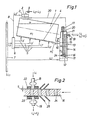
- the tank 1 containing the coal dust for storage is inclined at an angle of approximately 10 ° to a horizontal and is provided with a tank dome 2 in the region of the highest point of the tank 1.
- the interior of the tank dome 2 is separated from the interior of the tank 1 by a filter 3.
- In the tank 1 there is an air-permeable floor 4.
- the space below the floor 4 is divided by webs or the like into four chambers into which the air lines 5 open, which are connected to an air distributor 6 which is supplied with compressed air by the combustion air line 7 is supplied. Compressed air can be introduced via the compressed air line 8 into the interior of the tank dome 2, which is connected to the atmosphere via a pipe socket provided with an adjustable throttle 9.
- the coal dust tank 1 is connected via the line 10 provided with a gate valve to the container 11, which carries the dosing furnishing contains.
- An air-permeable base 12 is also located in the lower area of the metering container 11.
- a compressed air line opens into the space below the base 12 and is connected to the combustion air line 7.
- On the wall of the metering container 11 are at a distance from one another and one above the other the level probes 13, 14 which control the replenishment of coal dust from the tank 1 into the metering container 11.
- the amount of coal dust K 2 contained in it is fluidized by the amount of air L 2 introduced into the metering container 11.
- an air quantity L 3 ' is introduced via the air distributor 6 via the air line 8 into the interior of the tank dome 2, preferably in a pulsating manner, as a result of which the filter 3 is seated Coal dust is shaken off and the filter is cleaned.
- an air quantity Lg ′′ is blown proportionately and in alternating order via the air lines 5 into the chambers below the air-permeable bottom, whereby the amount of coal dust K 1 in the coal dust tank starts to move and is conveyed through the connecting line 10 into the interior of the metering container 11 This continues until the level of coal dust in the metering container 11 has reached the level probe 13, as a result of which the air supply to the air lines 5 in the air distributor 6 is switched off.
- a further amount of air L 3 ' is then introduced into the interior for a short period of time the tank dome 2 for the purpose of cleaning the filter 3 again.
- the mouth 15 of the connecting line 10 does not necessarily have to lie above the upper level probe 13, as shown; it is also possible to arrange them lower, which has an advantageous effect on the overall height, because as a result the metering container 11 is located higher than the tank 1. Under such circumstances it can even be achieved that the dosing container can be attached to the front of a tank or can be integrated into it. As a rule, this is advantageously possible if the average density of the fluidized coal dust in the metering container 11 is below 400 kg / m 3 . Under these conditions, the coal dust slips into the metering container 11 even if the mouth 15 of the connecting line 10 is more or less far below the level of the coal dust column in the metering container 11.
- the metering disk 16 is provided with cells 24 which are arranged at regular intervals along a circle around the axis of rotation.
- the cells are bores in the disk 16 which are parallel to the axis; however, the cells 24 can also consist of cutouts located on the circumference of the disk 16.
- the line 18 supplying the carrier air opens directly above the disk 16 at a distance from the axis of rotation of the disk 16, so that the mouth lies coaxially with the cells 24.
- the mouth of the line of the metering disk 16 which discharges the carrier air laden with coal dust is in a corresponding position.
- the tube mouths of the tubes 18, 19 are advantageously provided with seals 22, 23 surrounding them.
- the discharge of the relatively small amounts of coal dust K 2 'per unit of time with the aid of the carrier air amount L 4 takes place by means of the metering device, which consists of a metering disk 16 arranged in the lower region of the container 11 and rotating in a horizontal plane, with its drive shaft and the drive motor 17, which is arranged on the lid of the metering container 11, and there is the pipes 18 and 19 through which the carrier air is supplied on the one hand and the air stream laden with coal dust is discharged on the other hand. Since compressed air is introduced into the metering container in order to fluidize the amount of coal dust K 2 , it is necessary to return the excess amount of air, which may still be loaded with small amounts of coal dust, via a line 20 into the interior of the tank 1.
- the metering device is advantageously seated with all its elements on the lid 21 of the metering container 11, in order to be able to exchange it in a simple manner, for example in the event of faults. In such a case, it is only necessary to detach the lid 21 from the container 11 and pull it upwards.
- the height of the coal dust column in the metering container 11 is approximately 400 to 800 mm and the amount of fluidizing air L 2 passing through the air-permeable base 12 is between 15 and 60 m 3 / h per square meter, preferably approximately 30 m 3 per square meter,
- Floor area is, corresponding to a pressure loss of the air volume L 2 when flowing through the floor 12 of about 200 to 400 WS, depending on the resistance of the air-permeable floor 12.
- the air volume L 2 is preferably regulated so that an average density of the fluidized coal dust K 2 in the dosing container 11 from about 200 to 250 kg / m 3 . Under such conditions, the coal dust has particularly favorable flow properties create so that it can be dosed well and precisely.
- the size of the air-permeable bottom 12 is approximately 0.2 to 0.6 m 2 per 1,000 kg / h of coal dust throughput, expediently approximately 0.4 m 2 per 1,000 kg / h of coal dust throughput, with something for smaller throughputs due to the edge influence larger and somewhat smaller area dimensions should be selected for larger throughputs. Under these conditions, particularly favorable movement conditions of the fluidized coal dust are obtained, in particular in the area of the metering disc 16.
- the metering container can have any cross-sectional shape; a round or square cross-section is expediently used. Depending on the conditions under consideration, one or more metering devices can be arranged next to one another in the metering container.
- the invention can be applied to the storage and the metered discharge not only of coal dust, but also of all fluidizable fine-grained products, depending on the material density, correspondingly adapted dimensions of the mechanical parts as well as the pressures and quantities are to be provided.
Landscapes
- Engineering & Computer Science (AREA)
- Mechanical Engineering (AREA)
- Chemical & Material Sciences (AREA)
- Combustion & Propulsion (AREA)
- General Engineering & Computer Science (AREA)
- Filling Or Emptying Of Bunkers, Hoppers, And Tanks (AREA)
Description
- Die Erfindung betrifft einen Kohlenstaubtank mit Einrichtung zum dosierten Austragen insbesondere kleiner Kohlenstaubmengen in einem gleichmäßigen Strom. Derartige Anlagen sind derzeit noch nicht bekannt, jedoch befinden sie sich in der Entwicklung.
- Aus der FR-A-24 13 298 ist ein Silo für Schüttgut mit einer danebenstehenden pneumatischen Fördereinrichtung bekannt, die das aus dem Silo mit pneumatischer Hilfe entnommene pulverige oder granulierte Schüttgut nach oben transportiert. Einzelheiten der pneumatisch unterstützten siloseitigen Entnahmevorrichtung sind nicht beschrieben. Die Fördereinrichtung besteht im wesentlichen aus einem aufrechtstehenden Kessel, der von oben befüllbar ist, von einem in Bodennähe endenden Rohr durchzogen ist, an dessen unterem offenen Ende ein Trichter angesetzt ist, in den ein Blasrohr mündet. In den Trichter eingeblasene Luft saugt das umgebende Schüttgut an und transportiert dieses durch das Rohr nach oben. Zwar ist durch Einstellung des Luftdruckes eine Beeinflussung der geförderten Schüttgutmenge möglich, doch hängt diese auch von der Korngröße und von der Fließfähigkeit ab und ist daher nicht eindeutig reproduzierbar.
- Versuche mit Hilfe rein mechanischer Mittel, wie z. B. Förderschnecken, Zellenräder etc. führten bei einem erheblichen, nicht vertretbaren Aufwand an maschinellen Anlagen usw. und bei einem relativ hohen Energieverbrauch zu absolut unbefriedigenden Ergebnissen.
- Der Erfindung liegt die Aufgabe zugrunde, aus einem größeren Lagertank feingemahlenen Kohlenstaub in den für Heizungszwecke benötigten geringen Mengen reproduzierbar und derart gleichmäßig herauszufördern, daß die damit gespeiste Kohlenstaubflamme, in der der Kohlenstaub Verweilzeiten von ca. 0,1 Sekunden hat, gleichmäßig und pulsationsfrei brennt. Dabei muß der in dem Tank druckfrei lagernde Kohlenstaub in eine Förderluftleitung eingetragen werden, in der ein Druck von etwa 0,1 bis 0,2 bar herrscht.
- Zur Lösung der der Erfindung zugrunde liegenden Aufgabe wird vorgeschlagen, einen Kohlenstaubtank mit einer Einrichtung zum dosierten Austragen insbesondere kleiner Kohlenstaubmengen in einem weitgehend gleichmäßigen Strom in der Weise auszubilden, daß er die im Anspruch 1 angegebenen Merkmale in Kombination miteinander aufweist. Weitere vorteilhafte Gestaltungen ergeben sich aus den Merkmalen der Unteransprüche. Ein derart erfindungsgemäß ausgebildeter Kohlenstaubtank ermöglicht einen einwandfreien und automatischen Betrieb selbst relativ kleiner Kohlenstaubfeuerungsanlagen und weiterhin die Unterbringung der Kohlenstaubtanks an räumlich beschränkten Stellen, so daß ihr nachträglicher Einbau in vorhandenen Räumen praktisch auf keine Schwierigkeiten stößt. Ein weiterer, wesentlicher Vorteil des erfindungsgemäß ausgebildeten Kohlenstaubtanks ist die leichte Zugänglichkeit zur bzw. Auswechselbarkeit der Dosier- und Austrageinrichtung im Dosierbehälter für den Fall, daß eine Störung aufgetreten sein sollte.
- Der Tankboden oder der gesamte Tank sind unter einem Winkel von 8° bis 15°, vorzugsweise unter einem Winkel von 10°, gegen die Horizontale geneigt, um das Abfließen des Kohlenstaubs zu begünstigen. Weiterhin sind mehrere am Boden in den Tank einmündende Druckluftleitungen vorgesehen, die von einem Luftverteiler in wechselnder Folge mit Druckluft beaufschlagt werden und daher periodisch, stoßweise pulsierend Luft in den Tank einblasen und den Kohlenstaub darin in Bewegung bringen, um das Abfließen weiter zu begünstigen. Eine weitere Unterstützung der Abförderung des Kohlenstaubs kann erreicht werden, wenn längs der tiefsten Stelle der Verbindungsleitung zwischen Kohlenstaubtank und Dosierbehälter ein mit vorzugsweise in Förderrichtung geneigten Luftaustrittsöffnungen versehenes Rohr angeordnet wird, das an den Luftverteiler angeschlossen und von diesem mit Druckluft versorgt wird.
- Ähnlich wie in der Heizölbevorratung in geschlossenen Räumen ist es auch bei der Erfindung möglich, Tankbatterien aufzustellen und beispielsweise zwei Kohlenstaubtanks einer einzigen Dosier- und Austrageinrichtung zuzuordnen.
- Die Erfindung soll nachfolgend unter Bezugnahme auf ein in den Zeichnungen dargestelltes Ausführungsbeispiel näher erläutert werden. Es zeigt :
- Figur 1 einen Schnitt durch den Kohlenstaubtank und den mit der Dosiereinrichtung versehenen Dosierbehälter in schematischer Darstellung, und
- Figur 2 einen Schnitt durch einen Teil der Dosiereinrichtung in vergrößertem Maßstab.
- Der den Kohlenstaub zwecks Lagerung enthaltende Tank 1 ist unter einem Winkel von etwa 10° gegen eine Horizontale geneigt und mit einem Tankdom 2 im Bereich der höchsten Stelle des Tanks 1 versehen. Der Innenraum des Tankdoms 2 ist gegen den Innenraum des Tanks 1 durch ein Filter 3 getrennt. Im Tank 1 befindet sich ein luftdurchlässiger Boden 4. Der Raum unterhalb des Bodens 4 ist durch Stege od. dgl. in vier Kammern unterteilt, in welche die Luftleitungen 5 einmünden, die an einen Luftverteiler 6 angeschlossen sind, welcher von der Verbrennungsluftleitung 7 mit Druckluft versorgt wird. Über die Druckluftleitung 8 kann Druckluft in den Innenraum des Tankdoms 2 eingeführt werden, welcher über einen mit einer einstellbaren Drossel 9 versehenen Rohrstutzen mit der Atmosphäre in Verbindung steht.
- Der Kohlenstaubtank 1 steht über die mit einem Absperrschieber versehene Leitung 10 mit dem Behälter 11 in Verbindung, welcher die Dosiereinrichtung enthält. Im unteren Bereich des Dosierbehälters 11 befindet sich ebenfalls ein luftdurchlässiger Boden 12. In den Raum unterhalb des Bodens 12 mündet eine Druckluftleitung, die an die Verbrennungsluftleitung 7 angeschlossen ist. An der Wand des Dosierbehälters 11 befinden sich im Abstand voneinander und übereinander die Niveausonden 13, 14, die den Nachschub an Kohlenstaub aus dem Tank 1 in den Dosierbehälter 11 steuern. Durch die in den Dosierbehälter 11 eingeleitete Luftmenge L2 wird die in ihm befindliche Kohlenstaubmenge K2 fluidisiert. Sinkt das Niveau der sich in fluidisiertem Zustand befindlichen Kohlenstaubmenge K2 bis zur unteren Niveausonde 14 ab, so wird über den Luftverteiler 6 eine Luftmenge L3' über die Luftleitung 8 in den Innenraum des Tankdoms 2 vorzugsweise pulsierend stoßartig eingeleitet, wodurch am Filter 3 sitzender Kohlenstaub abgeschüttelt und der Filter gereinigt wird. Anschließend wird von dem Luftverteiler 6 eine Luftmenge Lg" anteilig und in wechselnder Folge über die Luftleitungen 5 in die Kammern unterhalb des luftdurchlässigen Bodens eingeblasen, wodurch die Kohlenstaubmenge K1 im Kohlenstaubtank in Bewegung gerät und durch die Verbindungsleitung 10 in den Innenraum des Dosierbehälters 11 gefördert wird. Dies geschieht so lange, bis das Kohlenstaubniveau im Dosierbehälter 11 die Niveausonde 13 erreicht hat, wodurch im Luftverteiler 6 die Luftzufuhr zu den Luftleitungen 5 abgeschaltet wird. Zweckmäßigerweise erfolgt anschließend die Einleitung einer weiteren Luftmenge L3' während einer kurzen Zeitspanne in den Innenraum des Tankdoms 2 zwecks erneuter Reinigung des Filters 3.
- Die Mündung 15 der Verbindungsleitung 10 muß nicht unbedingt, wie dargestellt, oberhalb der oberen Niveausonde 13 liegen ; es ist auch möglich, diese tiefer anzuordnen, was sich vorteilhaft auf die Bauhöhe auswirkt, weil dadurch der Dosierbehälter 11 gegenüber dem Tank 1 höher zu liegen kommt. Unter solchen Umständen läßt sich sogar erreichen, daß der Dosierbehälter an die Stirnseite eines Tanks angebaut oder in diesen integriert werden kann. Dies ist in der Regel vorteilhafterweise dann möglich, wenn die mittlere Dichte des fluidisierten Kohlenstaubs im Dosierbehälter 11 unter 400 kg/m3 liegt. Unter diesen Bedingungen rutscht der Kohlenstaub auch dann in den Dosierbehälter 11 hinein, wenn die Mündung 15 der Verbindungsleitung 10 mehr oder weniger weit unterhalb des Niveaus der Kohlenstaubsäule im Dosierbehälter 11 liegt.
- Die Dosierscheibe 16 ist, wie insbesondere aus Fig. 2 hervorgeht, mit Zellen 24 versehen, die in regelmäßigen Abständen längs eines Kreises um die Drehachse angeordnet sind. Im einfachsten Falle handelt es sich bei den Zellen um achsparallele Bohrungen in der Scheibe 16 ; die Zellen 24 können aber auch aus am Umfang der Scheibe 16 befindlichen Ausschnitten bestehen. Die die Trägerluft zuführende Leitung 18 mündet unmittelbar oberhalb der Scheibe 16 in einem Abstand von der Drehachse der Scheibe 16, so daß die Mündung koaxial zu den Zellen 24 liegt. In entsprechender Lage befindet sich die Mündung der die mit Kohlenstaub beladenen Trägerluft abführenden Leitung der Dosierscheibe 16. Vorteilhafterweise sind die Rohrmündungen der Rohre 18, 19 mit sie umgebenden Dichtungen 22, 23 versehen. Diese haben die Aufgabe, die Verwirbelung des Kohlenstaubs in unmittelbarer Nachbarschaft der Zellen 24 durch aus den Spalten S zwischen den Rohrmündungen und der Dosierscheibe 16 austretenden Leckluftmengen geringstmöglich zu halten und damit die Füllung der Zellen 24 in der Dosierscheibe 16 mit Kohlenstaub nicht zu beeinträchtigen. Dies wird weiterhin dadurch gefördert, daß die Zellen in der Dosierscheibe 16 gekrümmt verlaufen, und zwar in Bewegungsrichtung gesehen, rückwärts gekrümmt sind, wie dies insbesondere aus Fig. 2 hervorgeht. Von Vorteil ist weiterhin die Anordnung schräg gestellter Leitbleche 25 in unmittelbarer Nachbarschaft der Mündungen der Rohre 18, 19.
- Der Austrag der relativ kleinen Kohlenstaubmengen K2' pro Zeiteinheit mit Hilfe der Trägerluftmenge L4 erfolgt mittels der Dosiereinrichtung, welche aus einer im unteren Bereich des Behälters 11 angeordneten, sich in einer horizontalen Ebene drehenden Dosierscheibe 16 mit ihrer Antriebswelle und dem Antriebsmotor 17, welcher auf dem Deckel des Dosierbehälters 11 angeordnet ist, sowie den Rohrleitungen 18 und 19 besteht, durch welche einerseits die Trägerluft zugeführt und andererseits der mit Kohlenstaub beladene Luftstrom abgeführt wird. Da zwecks Fluidisierung der Kohlenstaubmenge K2 im Dosierbehälter Druckluft in diesen eingeführt wird, ist es erforderlich, die überschüssige Luftmenge, die gegebenenfalls noch mit geringen Mengen Kohlenstaubs beladen sein kann, über eine Leitung 20 in den Innenraum des Tanks 1 zurückzuführen.
- Vorteilhafterweise sitzt die Dosiereinrichtung mit allen ihren Elementen an dem Deckel 21 des Dosierbehälters 11, um diese beispielsweise bei Störungen in einfacher Weise austauschen zu können. Es ist in einem solchen Fall lediglich notwendig, den Deckel 21 vom Behälter 11 zu lösen und diesen nach oben abzuziehen.
- Es hat sich als günstig erwiesen, wenn die Höhe der Kohlenstaubsäule im Dosierbehälter 11 etwa 400 bis 800 mm und die durch den luftdurchlässigen Boden 12 hindurchtretende Fluidisierungsluftmenge L2 zwischen 15 und 60 m3/h pro Quadratmeter, vorzugsweise etwa 30 m3 pro Quadratmeter, Bodenfläche beträgt, entsprechend einem Druckverlust der Luftmenge L2 beim Durchströmen des Bodens 12 von etwa 200 bis 400 WS, je nach dem Widerstand des luftdurchlässigen Bodens 12. Die Luftmenge L2 wird vorzugsweise so eingeregelt, daß sich eine mittlere Dichte des fluidisierten Kohlenstaubs K2 im Dosierbehälter 11 von etwa 200 bis 250 kg/m3 einstellt. Unter derartigen Bedingungen hat der Kohlenstaub besonders günstige Fließeigenschaften, so daß er sich gut und exakt dosieren läßt.
- Die Größe des luftdurchlässigen Bodens 12 beträgt etwa 0,2 bis 0,6 m2 pro 1 000 kg/h Kohlenstaubdurchsatz, zweckmäßigerweise ca. 0,4 m2 pro 1 000 kg/h Kohlenstaubdurchsatz, wobei aus Gründen des Randeinflusses für kleinere Durchsätze etwas größere und für größere Durchsätze etwas kleinere Flächendimensionen gewählt werden sollten. Unter diesen Bedingungen erhält man besonders günstige Bewegungsverhältnisse des fluidisierten Kohlenstaubs, insbesondere im Bereich der Dosierscheibe 16. Der Dosierbehälter kann jedwede Querschnittsform aufweisen, zweckmäßigerweise verwendet man einen runden oder quadratischen Querschnitt. Je nach den in Betracht kommenden Verhältnissen können ein oder mehr Dosiereinrichtungen nebeneinander im Dosierbehälter angeordnet sein.
- Die Erfindung läßt sich auf die Lagerung und das dosierte Austragen nicht nur von Kohlenstaub, sondern auch von allen fluidisierbaren feinkörnigen Produkten anwenden, wobei je nach der Materialdichte entsprechend angepaßte Dimensionen der mechanischen Teile sowie der Drücke und Mengen vorzusehen sind.
Claims (11)
Applications Claiming Priority (1)
| Application Number | Priority Date | Filing Date | Title |
|---|---|---|---|
| PCT/DE1980/000033 WO1981002773A1 (fr) | 1980-03-19 | 1980-03-19 | Reservoir de poussier de charbon pourvu d'un dispositif d'evacuation dosee, en particulier de petites quantites de poussier |
Publications (3)
| Publication Number | Publication Date |
|---|---|
| EP0054018A1 EP0054018A1 (de) | 1982-06-23 |
| EP0054018B1 true EP0054018B1 (de) | 1984-10-17 |
| EP0054018B2 EP0054018B2 (de) | 1988-03-09 |
Family
ID=6711739
Family Applications (1)
| Application Number | Title | Priority Date | Filing Date |
|---|---|---|---|
| EP19800900548 Expired EP0054018B2 (de) | 1980-03-19 | 1980-03-19 | Kohlenstaubtank mit einrichtung zum dosierten austragen, insbesondere kleiner kohlenstaubmengen |
Country Status (3)
| Country | Link |
|---|---|
| EP (1) | EP0054018B2 (de) |
| DE (1) | DE3069444D1 (de) |
| WO (1) | WO1981002773A1 (de) |
Families Citing this family (6)
| Publication number | Priority date | Publication date | Assignee | Title |
|---|---|---|---|---|
| FR2595188B1 (fr) * | 1986-03-07 | 1989-05-19 | Jerome Jean | Epandeur perfectionne de produits pulverulents, notamment pour l'epandage d'engrais en poudre |
| DE3617352A1 (de) * | 1986-05-23 | 1987-11-26 | Ruhrkohle Carborat Gmbh | Druckluftfoerder- und dosiereinrichtung |
| EP0608894A1 (de) * | 1993-01-29 | 1994-08-03 | Nippon Paint Co., Ltd. | Positiv arbeitende lichtempfindliche Harzzusammensetzungen |
| SG72914A1 (en) * | 1999-01-14 | 2000-09-19 | Sky Technology Pte Ltd | A particulate matter storage container and method and filter |
| WO2003095492A1 (en) | 2002-05-06 | 2003-11-20 | The Government Of The United States Of America, Represented By The Secretary, Department Of Health And Human Services | Identification of novel broadly cross-reactive hiv-1 neutralizing human monoclonal antibodies |
| CN105523382A (zh) * | 2016-01-22 | 2016-04-27 | 江苏泰禾金属工业有限公司 | 一种双防尘灌料装置 |
Family Cites Families (4)
| Publication number | Priority date | Publication date | Assignee | Title |
|---|---|---|---|---|
| US2740672A (en) * | 1953-03-11 | 1956-04-03 | Fuller Co | Conveying apparatus |
| GB887309A (en) * | 1959-08-05 | 1962-01-17 | Simon Ltd Henry | Improved method of and apparatus for the conveying of powdered or pulverulent dry material in bulk |
| FR2413298A1 (fr) * | 1977-12-30 | 1979-07-27 | Fives Cail Babcock | Elevateur pneumatique, notamment pour le vidage de silos |
| DE2839417A1 (de) * | 1978-09-11 | 1980-03-20 | Schoppe Fritz | Dosierbehaelter fuer kohlenstaubtanks |
-
1980
- 1980-03-19 DE DE8080900548T patent/DE3069444D1/de not_active Expired
- 1980-03-19 EP EP19800900548 patent/EP0054018B2/de not_active Expired
- 1980-03-19 WO PCT/DE1980/000033 patent/WO1981002773A1/de not_active Ceased
Also Published As
| Publication number | Publication date |
|---|---|
| WO1981002773A1 (fr) | 1981-10-01 |
| EP0054018A1 (de) | 1982-06-23 |
| DE3069444D1 (en) | 1984-11-22 |
| EP0054018B2 (de) | 1988-03-09 |
Similar Documents
| Publication | Publication Date | Title |
|---|---|---|
| EP2826567B1 (de) | Verfahren zum Zuführen von Hilfsmaterial und Hilfsmaterialaufnahmebehälter | |
| EP1751041B1 (de) | Verfahren und vorrichtung zur inertisierung von vakuumförderern | |
| EP1952892B1 (de) | Pulversprühbeschichtungsanlage und Pulversprühbeschichtungsverfahren | |
| EP1427657B1 (de) | Vorrichtung und verfahren zum überführen eines staub-, pulver-, korn- oder granulatartigen fördergutes aus einem lagerbehälter in einen arbeits- oder überführungsbehälter od.dgl. aufnahmeraum | |
| EP0054018B1 (de) | Kohlenstaubtank mit einrichtung zum dosierten austragen, insbesondere kleiner kohlenstaubmengen | |
| DE60014050T2 (de) | Vorrichtung und verfahren zum füllen von einem silo | |
| WO1991002586A1 (de) | Schüttgutreaktor | |
| EP0036894A1 (de) | Kohlenstaubtank mit Einrichtung zum dosierten Austragen insbesondere kleiner Kohlenstaubmengen | |
| DE2639054A1 (de) | Filtervorrichtung fuer radioaktive verunreinigungen mit einrichtungen zur zufuhr von filtermaterial | |
| DE2935773A1 (de) | Anlage zum filtern eines verunreinigten fliessmittels unter verwendung eines granulierten, pneumatisch wieder erneuerbaren materials | |
| DE102004021612A1 (de) | Verfahren und Vorrichtung zum pneumatischen Behandeln pulverförmiger Stoffe | |
| DE102007040896A1 (de) | Einheit und Verfahren zum Herstellen einer Vorrichtung zum Abscheiden von Nasslack-Overspray | |
| DE2623705A1 (de) | Austragvorrichtung fuer schuettgueter | |
| DE3701988A1 (de) | Verfahren und vorrichtung zum aufbereiten von schuettgut, insbesondere strahlgut | |
| EP0543100A1 (de) | Verfahren und Vorrichtung zum Austragen von Feststoff | |
| DE2839417C2 (de) | ||
| DE4405597C1 (de) | Filtervorrichtung für mit Partikeln verunreinigtes Gas | |
| EP0400331B2 (de) | Grossraumsilo für staubförmiges und feinkörniges Schüttgut | |
| DE898109C (de) | Einrichtung zum Umwaelzen bzw. Mischen von mehligen, pulverfoermigen bzw. koernigen Stoffen | |
| DE2254470C3 (de) | Verfahren und Vorrichtung zum Mischen und Füllen von verschiedenen Granulaten in Zigarettenfiltern | |
| DD140965A5 (de) | Saatgutbeizapparat | |
| DE19538622C1 (de) | Vorrichtung zum Dosieren und Fördern von pulvrigen und rieselfähigen Feststoffen | |
| DE7531503U (de) | Entleerungsvorrichtung an flachboedigen schuettgutsilos | |
| DD149494A5 (de) | Kohlenstaubtank und einrichtung zum dosierten austragen insbesondere kleiner kohlenstaubmengen | |
| DE102012224054A1 (de) | Vorrichtung zum Befördern eines Betriebsstoffes |
Legal Events
| Date | Code | Title | Description |
|---|---|---|---|
| PUAI | Public reference made under article 153(3) epc to a published international application that has entered the european phase |
Free format text: ORIGINAL CODE: 0009012 |
|
| AK | Designated contracting states |
Kind code of ref document: A1 Designated state(s): DE FR GB |
|
| 17P | Request for examination filed |
Effective date: 19820419 |
|
| RBV | Designated contracting states (corrected) |
Designated state(s): DE FR GB |
|
| GRAA | (expected) grant |
Free format text: ORIGINAL CODE: 0009210 |
|
| AK | Designated contracting states |
Kind code of ref document: B1 Designated state(s): DE FR GB |
|
| REF | Corresponds to: |
Ref document number: 3069444 Country of ref document: DE Date of ref document: 19841122 |
|
| ET | Fr: translation filed | ||
| PLBI | Opposition filed |
Free format text: ORIGINAL CODE: 0009260 |
|
| 26 | Opposition filed |
Opponent name: AZO MASCHINENFABRIK ADOLF ZIMMERMANN GMBH & CO Effective date: 19850716 |
|
| PUAH | Patent maintained in amended form |
Free format text: ORIGINAL CODE: 0009272 |
|
| STAA | Information on the status of an ep patent application or granted ep patent |
Free format text: STATUS: PATENT MAINTAINED AS AMENDED |
|
| 27A | Patent maintained in amended form |
Effective date: 19880309 |
|
| AK | Designated contracting states |
Kind code of ref document: B2 Designated state(s): DE FR GB |
|
| ET3 | Fr: translation filed ** decision concerning opposition | ||
| PG25 | Lapsed in a contracting state [announced via postgrant information from national office to epo] |
Ref country code: DE Effective date: 19881201 |
|
| PGFP | Annual fee paid to national office [announced via postgrant information from national office to epo] |
Ref country code: FR Payment date: 19980330 Year of fee payment: 19 |
|
| PGFP | Annual fee paid to national office [announced via postgrant information from national office to epo] |
Ref country code: GB Payment date: 19980331 Year of fee payment: 19 |
|
| PG25 | Lapsed in a contracting state [announced via postgrant information from national office to epo] |
Ref country code: GB Free format text: LAPSE BECAUSE OF NON-PAYMENT OF DUE FEES Effective date: 19990319 |
|
| GBPC | Gb: european patent ceased through non-payment of renewal fee |
Effective date: 19990319 |
|
| PG25 | Lapsed in a contracting state [announced via postgrant information from national office to epo] |
Ref country code: FR Free format text: LAPSE BECAUSE OF NON-PAYMENT OF DUE FEES Effective date: 19991130 |
|
| REG | Reference to a national code |
Ref country code: FR Ref legal event code: ST |