EP0053970B1 - Vorrichtung zum gerichteten Verbinden von insbesondere rohrförmigen Gerüstelementen - Google Patents
Vorrichtung zum gerichteten Verbinden von insbesondere rohrförmigen Gerüstelementen Download PDFInfo
- Publication number
- EP0053970B1 EP0053970B1 EP81401879A EP81401879A EP0053970B1 EP 0053970 B1 EP0053970 B1 EP 0053970B1 EP 81401879 A EP81401879 A EP 81401879A EP 81401879 A EP81401879 A EP 81401879A EP 0053970 B1 EP0053970 B1 EP 0053970B1
- Authority
- EP
- European Patent Office
- Prior art keywords
- clamp
- radial
- collar
- assembly device
- arm
- Prior art date
- Legal status (The legal status is an assumption and is not a legal conclusion. Google has not performed a legal analysis and makes no representation as to the accuracy of the status listed.)
- Expired
Links
Images


Classifications
-
- E—FIXED CONSTRUCTIONS
- E04—BUILDING
- E04G—SCAFFOLDING; FORMS; SHUTTERING; BUILDING IMPLEMENTS OR AIDS, OR THEIR USE; HANDLING BUILDING MATERIALS ON THE SITE; REPAIRING, BREAKING-UP OR OTHER WORK ON EXISTING BUILDINGS
- E04G7/00—Connections between parts of the scaffold
- E04G7/30—Scaffolding bars or members with non-detachably fixed coupling elements
- E04G7/302—Scaffolding bars or members with non-detachably fixed coupling elements for connecting crossing or intersecting bars or members
- E04G7/306—Scaffolding bars or members with non-detachably fixed coupling elements for connecting crossing or intersecting bars or members the added coupling elements are fixed at several bars or members to connect
- E04G7/307—Scaffolding bars or members with non-detachably fixed coupling elements for connecting crossing or intersecting bars or members the added coupling elements are fixed at several bars or members to connect with tying means for connecting the bars or members
-
- E—FIXED CONSTRUCTIONS
- E04—BUILDING
- E04G—SCAFFOLDING; FORMS; SHUTTERING; BUILDING IMPLEMENTS OR AIDS, OR THEIR USE; HANDLING BUILDING MATERIALS ON THE SITE; REPAIRING, BREAKING-UP OR OTHER WORK ON EXISTING BUILDINGS
- E04G7/00—Connections between parts of the scaffold
- E04G7/30—Scaffolding bars or members with non-detachably fixed coupling elements
- E04G7/32—Scaffolding bars or members with non-detachably fixed coupling elements with coupling elements using wedges
-
- Y—GENERAL TAGGING OF NEW TECHNOLOGICAL DEVELOPMENTS; GENERAL TAGGING OF CROSS-SECTIONAL TECHNOLOGIES SPANNING OVER SEVERAL SECTIONS OF THE IPC; TECHNICAL SUBJECTS COVERED BY FORMER USPC CROSS-REFERENCE ART COLLECTIONS [XRACs] AND DIGESTS
- Y10—TECHNICAL SUBJECTS COVERED BY FORMER USPC
- Y10T—TECHNICAL SUBJECTS COVERED BY FORMER US CLASSIFICATION
- Y10T403/00—Joints and connections
- Y10T403/30—Laterally related members connected by latch means, e.g., scaffold connectors
Definitions
- the present invention relates to a directional assembly device between the elements, in particular tubular, of a scaffolding. More particularly, it relates to such a device adapted to connect fixedly, rigidly and in a determined direction, horizontal elements, such as crosspieces, beams, stringers and diagonals, on vertical elements, such as uprights and posts, in order to form a knot. where the forces transmitted by the horizontal elements arrive at a common point located in the center of the vertical elements and without producing on them any moment of gyration.
- the directional assembly device between the tubular elements, of a scaffolding for example which is the subject of the present invention, is designed so as to eliminate the aforementioned drawbacks of the known assembly devices, by ensuring stability directional determined to the horizontal elements with respect to the vertical elements and vice versa, both in a horizontal plane and in a vertical plane, this directional stability being obtained from the start of assembly without requiring, for example, checking the squareness of the elements between them at the location of the nodes and / or play, during assembly, on the orientation of these elements before permanently locking them in position by acting on the keyways.
- such an assembly device between the horizontal and vertical elements of a tubular scaffolding is constituted by a ring carrying four radial arms, square the one with respect to the other, engaged on a vertical element, each arm being adapted to engage in a flange, integral with the end of the corresponding horizontal element and provided with bosses intended to bear on the ring, on either side of the arm in question, in order to provide this horizontal element with an exact direction in the extension of this arm, this flange being blocked on the latter by the forced insertion of a key in diametrically opposite openings, the end of the horizontal element of which is provided behind the flange, this key passing through, between these openings, a corresponding rectangular hole situated in the engaged arm of the ring.
- each flange has a central bore, adapted to allow the partial fitting of the corresponding end of the element which carries it fixed by welding, this flange being provided, on the side opposite to its support bosses, with two diametrically opposite notches and corresponding to the rectangular key engagement openings at the end of the element, the bottom of these notches being adapted to serve as support for the face of the key which pushes this flange towards said assembly ring , when the other opposite face of this force-fitted key comes into contact with the outside width side of the hole of the radial arm engaged in this flange.
- each flange is provided so that its lateral bosses respectively bear on the corresponding sides of the radial arms situated on either side of the arm on which this flange is engaged, thereby providing the latter with a seat of greater support on the ring and, consequently, an exact orientation in the extension of the engaged arm.
- the present invention provides another flange design, integral with the corresponding end of this crosspiece, this flange carrying lateral bosses, adapted to bear on the corresponding side of the bosses of the flanges of the mounted elements and comprising two diametrically opposite front projections, designed to engage respectively on the top and the bottom of the arm in question and provided with openings d 'Key engagement, similar to those of the ends of the other elements and arranged to cooperate in the same way with the rectangular hole in the arm.
- the assembly ring is provided, between its radial arms, with intermediate external ribs, the peripheral edge of which is designed to receive the bosses of each flange in support and provide the latter ci, as well as the horizontal element which carries it, a direction of fixing exactly in the axial extension of the radial arm which is engaged in this flange.
- each intermediate ribs to the radial arms are provided in the form of angular projections, each outer edge of which is respectively perpendicular to the longitudinal axis of the radial arm on which it arises, the corresponding lateral boss of each flange being adapted to bear. on this edge near the top of the projection considered.
- each part of the rib between two arms may be provided, optionally, with a cylindrical hole suitable for the forced introduction of a conical pin for fixing a yoke end of the diagonal or triangulation bar.
- the assembly ring is in the form of a star, each branch of which constitutes a radial arm provided with a radial V-shaped recess and lateral bosses at this recess, designed in the form of steps and adapted to receive the support from the front end of said flange or yoke engaged on this arm and secured to the corresponding radial tubular element, these support steps being provided on the two faces, upper and lower , of each branch or arm and over a sufficient width and thickness, determined so as to ensure a substantial seat at the end of said flange and directional stability to the radial tubular element, both in a vertical plane and in a horizontal plane, during the keying operation of the assembly.
- each branch is provided on its lower face with a single step-shaped boss, while its upper face has two successive bosses forming two steps, this arrangement being designed to allow a certain movement in the vertical plane at the radial tubular element during engagement and causing the automatic tilting in the insertion position of the captive key carried by the flange or yoke of this element.
- each flange consists of two L-shaped elements fixed together by the edge of their small wing, the edge of their large wing being adapted to the shape of the corresponding step of the ring to come into abutment. stable on the latter.
- one of the L-shaped elements has a flat key penetration recess closed on its four sides, while, in the other element, the corresponding recess opens into the small wing, in order to allow the introduction of the tip end of the key provided slightly swollen and make it captive of this element when the flange formed by these two elements will be fixed in manufacture on the end of the radial tubular element.
- the flange element having the recess opening into its small wing is provided with an internal cavity corresponding to the bulge of the tip end of the captive key and allowing the latter to be retracted during the 'engagement of the flange on a branch of the ring, this flange element being engaged on the steps of the upper face of this branch.
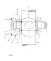
- the device for assembling tubular elements consists of a ring 1 provided with four radial arms 2, arranged at right angles to each other. other, this ring 1 being engaged on a vertical tubular element 3 and each arm being adapted to engage in a flange 4 (shown in section in FIG. 1), integral with the end of a horizontal tubular element 5 (shown dotted for easier understanding).
- This flange 4 is provided with lateral bosses 6, intended to bear on the body of the ring 1, or on the corresponding side of the radial arms 2 (as shown in FIG. 1) located on either side of the arm fitted in the end flange of the horizontal tubular element 5 considered.
- This flange is locked in the support position by means of a key (not shown) engaged in the diametrically opposite openings 7, 8 formed in the end of the horizontal element 5 behind the flange 4, this key crossing between these openings 7, 8 a rectangular hole 9 with which each radial arm 2 is provided.
- the ring 1 has a flared bore at its two opposite ends 10, 11 and suitable for its fixing by welding to the vertical tubular element 3, or for its positioning in a fixed position, although pivoting, on this element 3 by means of a frustoconical ring (not shown), welded on the latter and whose upper end, of smaller diameter, can engage in the lower flared end 11 of the ring 1.
- the flange 4 has a central bore 12, adapted to allow the partial fitting of the end of the tubular element 5 and the fixing by welding of the flange on the latter.
- This flange further comprises, on the side opposite to its bosses 6, that is to say on the side of the element 5, two notches 13, diametrically opposite and corresponding to the rectangular openings 7, 8 for key fitting and , there, to the rectangular hole 9 of the radial arm 2.
- the bottom of these notches is adapted to serve as a support for the face of the key which pushes the flange 4 towards the ring 1, when the other face opposite of this key is in contact with the outer edge 14 of the rectangular hole 9.
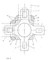
- This flange 15 fixed identically to that of the other flanges 4 at the end of a tubular element 16, is provided with lateral bosses 17, adapted to bear on the side of the bosses 6 of the other flanges 4, and comprises two front projections 18, 19 diametrically opposite, framing the top and bottom of the radial arm 2 engaged in it, and provided with key engagement openings 20 (shown in dotted lines in FIG. 1) similar and of the same arrangement as those of ends of other elements 5.
- the assembly ring 1 is provided, between its radial arms 2, with angular external ribs 21, the edges of which serve to support the lateral bosses 22 of the flanges 15 'carried by tubular elements 23.
- these flanges are designed in the same way as the flanges 4 (of FIG. 1), except that their bosses 22 are less laterally spaced and less prominent than the bosses 6 of these flanges.
- This assembly arrangement makes it possible to mount four horizontal elements perpendicular to each other on the same ring, without their identical flanges interfering with each other.
- each support rib 21 has a cylindrical hole 24, suitable for the forced introduction of a conical pin for fixing a yoke end of the diagonal or triangulation bar.
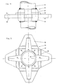
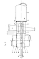
- the ring 31, shown in FIGS. 4 and 5, engaged and fixed on a vertical tubular element 32 is in the form of a star with four branches 33 each of which constitutes a radial arm adapted to receive the engagement of a flange or yoke 34, shown in FIGS. 6 to 8, the assembly being blocked, as seen in better in FIG. 9, by means of a flat key 35.
- Each branch 33 of the ring is provided with a V-shaped radial recess 36, opening out by its flaring on the outer wall of the tube 32.
- Each branch 33 comprises also, on either side of its recess 36, lateral bosses 37, 38, 39, designed in the form of steps and adapted to receive the support of the front ends 40, 41 of the flange 34, integral with the element radial tubular 42.
- these support steps s have provided on the two upper 43 and lower 44 faces of each branch 33, over a thickness and a sufficient and determined width to ensure a substantial seat at the corresponding ends 40, 41 of the flange 34 and a directional stability to the radial tubular element 42, both in a vertical plane and in a horizontal plane, during the locking operation of the key 35.
- the ring 31, as best seen in Figure 5, is fixed to the vertical tubular element 32 at several radial points provided by the intermediate sectors 45, 46, 47, 48 to the radial recesses 36 of the branches 33 of this ring.
- each branch 33 the bosses or flange support steps provided on each branch 33 are distributed so that there are two steps 37, 38 on the upper face 43 and a single step 39 on the underside 44 of this branch, this arrangement being adopted to allow the radial tubular element 42, during engagement, a certain movement in the vertical plane and cause the insertion, so to speak, automatically of the captive key 35 in the recess 36 of the branch 33 and its penetration following in the lower recess of the flange 34.
- each flange or yoke 34 consists of two L-shaped elements 49, 50 fixed together by the edge of their small wing 51, the edge of their large wing being adapted to the shape of the step 37, 39 corresponding to the branch 33, to come into firm and stable support on these steps.
- the lower element 50 comprises a recess 52 for penetrating the end of the key tip 35, closed on its four sides
- the upper element 49 comprises a recess 53 opening into the small wing 51, in order to allow the introduction of the key 35, the tip end of which is swollen laterally, and making it captive when the flange 34 formed by these two elements will be fixed during manufacture to the end of the radial tubular element 42.
- the upper element 49 further comprises an internal cavity 54 corresponding to its recess 52 and having a width sufficient to accommodate the point bulge of the key and retract it when the flange engages on the branch 33 chosen from the ring 31.
Landscapes
- Engineering & Computer Science (AREA)
- Architecture (AREA)
- Mechanical Engineering (AREA)
- Civil Engineering (AREA)
- Structural Engineering (AREA)
- Mutual Connection Of Rods And Tubes (AREA)
Claims (14)
Priority Applications (1)
| Application Number | Priority Date | Filing Date | Title |
|---|---|---|---|
| AT81401879T ATE18785T1 (de) | 1980-12-04 | 1981-11-27 | Vorrichtung zum gerichteten verbinden von insbesondere rohrfoermigen geruestelementen. |
Applications Claiming Priority (4)
| Application Number | Priority Date | Filing Date | Title |
|---|---|---|---|
| FR8025734A FR2495672A1 (fr) | 1980-12-04 | 1980-12-04 | Dispositif d'assemblage entre les elements, notamment tubulaires, d'un echafaudage |
| FR8025734 | 1980-12-04 | ||
| FR8120117 | 1981-10-27 | ||
| FR8120117A FR2515238A1 (fr) | 1981-10-27 | 1981-10-27 | Dispositif d'assemblage directionnel entre les elements d'un echafaudage, notamment tubulaire |
Publications (2)
| Publication Number | Publication Date |
|---|---|
| EP0053970A1 EP0053970A1 (de) | 1982-06-16 |
| EP0053970B1 true EP0053970B1 (de) | 1986-03-26 |
Family
ID=26222103
Family Applications (1)
| Application Number | Title | Priority Date | Filing Date |
|---|---|---|---|
| EP81401879A Expired EP0053970B1 (de) | 1980-12-04 | 1981-11-27 | Vorrichtung zum gerichteten Verbinden von insbesondere rohrförmigen Gerüstelementen |
Country Status (8)
| Country | Link |
|---|---|
| US (1) | US4530616A (de) |
| EP (1) | EP0053970B1 (de) |
| BR (1) | BR8107883A (de) |
| CA (1) | CA1204803A (de) |
| DE (1) | DE3174216D1 (de) |
| ES (1) | ES8300370A1 (de) |
| IT (1) | IT1168565B (de) |
| OA (1) | OA06961A (de) |
Cited By (1)
| Publication number | Priority date | Publication date | Assignee | Title |
|---|---|---|---|---|
| US10925825B2 (en) | 2012-05-25 | 2021-02-23 | Cosmetic Warriors Limited | Composition |
Families Citing this family (14)
| Publication number | Priority date | Publication date | Assignee | Title |
|---|---|---|---|---|
| FR2553456B1 (fr) * | 1983-10-18 | 1986-01-24 | Roux Marcel | Dispositif d'assemblage directionnel entre les elements tubulaires horizontaux et verticaux d'un echafaudage |
| DE3344939A1 (de) * | 1983-12-13 | 1985-06-20 | geb. Layher Ruth 7129 Güglingen Langer | Zerlegbare fachwerkkonstruktion |
| EP0147496A1 (de) * | 1984-01-05 | 1985-07-10 | Gerhard Dobersch | Vorrichtung zum Anschliessen von Gerüststreben an die Gerüst-ständer eines Modul-Baugerüstes |
| FR2577964B1 (fr) * | 1985-02-27 | 1987-03-27 | Cegedur | Noeud d'echafaudage ou de structure similaire et procede d'assemblage |
| JPH02178442A (ja) * | 1988-12-28 | 1990-07-11 | Tatsuo Ono | 支柱の連結方法及び支柱装置 |
| NL9101141A (nl) * | 1991-07-01 | 1993-02-01 | Sgb Holdings Ltd Namens Deze R | Verbindingsconstructie voor buizen, in het bijzonder voor toepassing bij steigers en dergelijke. |
| ES2078833B1 (es) * | 1992-08-06 | 1996-08-16 | Castillo Cabello Eugenio Del | Perfeccionamientos introducidos en escalerillas para andamios de la construccion |
| CA2201535C (en) * | 1997-04-02 | 2006-09-19 | Aluma Systems Corp. | Scaffolding connector |
| DE19844613A1 (de) * | 1998-09-29 | 2000-03-30 | Plettac Ag | Vertikales Gerüstrohr mit verbesserter Lastaufnahmefähigkeit |
| CA2634573C (en) * | 2008-06-10 | 2011-05-24 | Athos Construction Products Inc. | Modular scaffold system |
| DE102011001796A1 (de) | 2011-04-05 | 2012-10-11 | Wilhelm Layher Verwaltungs-Gmbh | Gerüststiel |
| WO2012163340A1 (de) | 2011-06-01 | 2012-12-06 | Wilhelm Layher Verwaltungs-Gmbh | Anordnung eines gerüstbauteils und eines vertikalen gerüstelements |
| US9835188B2 (en) * | 2013-03-14 | 2017-12-05 | Titan Formwork Systems Llc | Universal wedge clamp |
| CN105863247A (zh) * | 2016-05-20 | 2016-08-17 | 江苏业强脚手架科技发展有限公司 | 一种具有锁块的直插式脚手架 |
Family Cites Families (6)
| Publication number | Priority date | Publication date | Assignee | Title |
|---|---|---|---|---|
| GB1278243A (en) * | 1968-09-24 | 1972-06-21 | Alfred Victor Elson | Mounting arrangements for scaffolding |
| GB1408566A (en) * | 1971-09-17 | 1975-10-01 | Evans & Sons Ltd C | Couplings for use in scaffold structures for coupling an upright member to a transom or ledger member |
| NL175840B (nl) * | 1973-10-10 | 1984-08-01 | Sgb Group Plc | Verbindingsconstructie voor toepassing in een buisvormige steiger of stelling. |
| DE2449124C3 (de) * | 1974-10-16 | 1980-01-03 | Eberhard 7129 Gueglingen Layher | Verbindungsvorrichtung für Gerüstelemente |
| NL7701060A (nl) * | 1977-02-02 | 1978-08-04 | Ipa Scaffolding Nederland B V | Bouwsteiger alsmede van draagnokken voorzien ringelement voor de staanders van zulk een steiger. |
| GB2043824B (en) * | 1979-03-08 | 1982-11-17 | Evans & Sons Ltd C | Connector assembly for scaffold structures |
-
1981
- 1981-11-27 EP EP81401879A patent/EP0053970B1/de not_active Expired
- 1981-11-27 DE DE8181401879T patent/DE3174216D1/de not_active Expired
- 1981-12-04 OA OA57558A patent/OA06961A/xx unknown
- 1981-12-04 ES ES507746A patent/ES8300370A1/es not_active Expired
- 1981-12-04 IT IT84984/81A patent/IT1168565B/it active
- 1981-12-04 BR BR8107883A patent/BR8107883A/pt unknown
- 1981-12-04 CA CA000391523A patent/CA1204803A/fr not_active Expired
-
1984
- 1984-03-02 US US06/585,434 patent/US4530616A/en not_active Expired - Fee Related
Cited By (1)
| Publication number | Priority date | Publication date | Assignee | Title |
|---|---|---|---|---|
| US10925825B2 (en) | 2012-05-25 | 2021-02-23 | Cosmetic Warriors Limited | Composition |
Also Published As
| Publication number | Publication date |
|---|---|
| ES507746A0 (es) | 1982-11-01 |
| DE3174216D1 (en) | 1986-04-30 |
| IT8184984A0 (it) | 1981-12-04 |
| OA06961A (fr) | 1983-07-31 |
| ES8300370A1 (es) | 1982-11-01 |
| CA1204803A (fr) | 1986-05-20 |
| EP0053970A1 (de) | 1982-06-16 |
| BR8107883A (pt) | 1982-09-08 |
| IT1168565B (it) | 1987-05-20 |
| US4530616A (en) | 1985-07-23 |
Similar Documents
| Publication | Publication Date | Title |
|---|---|---|
| EP0053970B1 (de) | Vorrichtung zum gerichteten Verbinden von insbesondere rohrförmigen Gerüstelementen | |
| EP0236185B1 (de) | Vorrichtung zum Befestigen einer Kopfstütze auf einen Fahrzeugsitz | |
| EP0974546B1 (de) | Verbindungsvorrichtung für metalische Gitterelementen | |
| EP0076774B1 (de) | Rohrgerüst, Verfahren zum Aufbau und horizontale Querbalken für dieses Gerüst | |
| CH635160A5 (fr) | Raccord pour echafaudages de batiment. | |
| EP0530114A1 (de) | Lösbare Verbindungsvorrichtung für metallische Gerüstelemente | |
| FR2524408A1 (fr) | Assemblages de balais d'essuie-glace | |
| EP0098784B1 (de) | Elastisches Montageverfahren von zwei Teilen | |
| EP2767499B1 (de) | Laschenverbindungsvorrichtung zur Verbindung von zwei Mastelementen, und Anordnung, die zwei Mastelemente und solche Laschenverbindungsvorrichtungen umfasst | |
| FR2718510A1 (fr) | Procédé et dispositif d'assemblage de profilés, et structure démontable en faisant application. | |
| EP0004806A1 (de) | Gerüstelemente mit Kupplungsvorrichtung | |
| EP0194215B1 (de) | Kupplung für Gerüste oder ähnliche Gefüge und Verfahren zur Montage | |
| EP0527086A1 (de) | Vorrichtung zur Kupplung und Verbindung eines Endes einer Traverse mit einem Pfosten, und Gerüst mit dieser Traverse, die an beiden Enden mit dieser Vorrichtung versehen ist | |
| EP0008555A1 (de) | Verbindungssystem zur Herstellung von Gerüsten und leichten Metallkonstruktionen | |
| EP0165859B1 (de) | Querverstrebungssystem von Pfeilern eines Gittermastes und mit einem solchen System ausgerüsteter Mast | |
| FR2495672A1 (fr) | Dispositif d'assemblage entre les elements, notamment tubulaires, d'un echafaudage | |
| FR2496741A3 (fr) | Echafaudage tubulaire et ses moyens d'assemblage | |
| FR2515238A1 (fr) | Dispositif d'assemblage directionnel entre les elements d'un echafaudage, notamment tubulaire | |
| FR2474087A1 (fr) | Echafaudage ou structure a tubes et colliers a montage rapide | |
| FR2878273A1 (fr) | Dispositif d'assemblage d'elements d'un echafaudage tubulaire | |
| EP0797715A1 (de) | Formveränderbare struktur | |
| FR2683249A1 (fr) | Piquet pour cloture. | |
| BE882018A (fr) | Raccord perfectionne pour echaffaudages | |
| FR2547845A1 (fr) | Barriere de circulation multidirectionnelle | |
| FR2483994A3 (fr) | Echafaudage tubulaire |
Legal Events
| Date | Code | Title | Description |
|---|---|---|---|
| PUAI | Public reference made under article 153(3) epc to a published international application that has entered the european phase |
Free format text: ORIGINAL CODE: 0009012 |
|
| AK | Designated contracting states |
Designated state(s): AT DE GB NL SE |
|
| TCAT | At: translation of patent claims filed | ||
| TCNL | Nl: translation of patent claims filed | ||
| 17P | Request for examination filed |
Effective date: 19820805 |
|
| DET | De: translation of patent claims | ||
| GRAA | (expected) grant |
Free format text: ORIGINAL CODE: 0009210 |
|
| AK | Designated contracting states |
Kind code of ref document: B1 Designated state(s): AT DE GB NL SE |
|
| PG25 | Lapsed in a contracting state [announced via postgrant information from national office to epo] |
Ref country code: NL Effective date: 19860326 Ref country code: AT Effective date: 19860326 |
|
| REF | Corresponds to: |
Ref document number: 18785 Country of ref document: AT Date of ref document: 19860415 Kind code of ref document: T |
|
| PG25 | Lapsed in a contracting state [announced via postgrant information from national office to epo] |
Ref country code: SE Effective date: 19860331 |
|
| REF | Corresponds to: |
Ref document number: 3174216 Country of ref document: DE Date of ref document: 19860430 |
|
| NLV1 | Nl: lapsed or annulled due to failure to fulfill the requirements of art. 29p and 29m of the patents act | ||
| PLBE | No opposition filed within time limit |
Free format text: ORIGINAL CODE: 0009261 |
|
| STAA | Information on the status of an ep patent application or granted ep patent |
Free format text: STATUS: NO OPPOSITION FILED WITHIN TIME LIMIT |
|
| 26N | No opposition filed | ||
| PGFP | Annual fee paid to national office [announced via postgrant information from national office to epo] |
Ref country code: GB Payment date: 19891031 Year of fee payment: 9 |
|
| PGFP | Annual fee paid to national office [announced via postgrant information from national office to epo] |
Ref country code: DE Payment date: 19891111 Year of fee payment: 9 |
|
| PG25 | Lapsed in a contracting state [announced via postgrant information from national office to epo] |
Ref country code: GB Effective date: 19901127 |
|
| GBPC | Gb: european patent ceased through non-payment of renewal fee | ||
| PG25 | Lapsed in a contracting state [announced via postgrant information from national office to epo] |
Ref country code: DE Effective date: 19910801 |