EP0053863B1 - Système de construction pour maison et maison contruite selon ce système - Google Patents
Système de construction pour maison et maison contruite selon ce système Download PDFInfo
- Publication number
- EP0053863B1 EP0053863B1 EP81201332A EP81201332A EP0053863B1 EP 0053863 B1 EP0053863 B1 EP 0053863B1 EP 81201332 A EP81201332 A EP 81201332A EP 81201332 A EP81201332 A EP 81201332A EP 0053863 B1 EP0053863 B1 EP 0053863B1
- Authority
- EP
- European Patent Office
- Prior art keywords
- dwelling
- columns
- facade
- elements
- units
- Prior art date
- Legal status (The legal status is an assumption and is not a legal conclusion. Google has not performed a legal analysis and makes no representation as to the accuracy of the status listed.)
- Expired
Links
Images


Classifications
-
- E—FIXED CONSTRUCTIONS
- E04—BUILDING
- E04H—BUILDINGS OR LIKE STRUCTURES FOR PARTICULAR PURPOSES; SWIMMING OR SPLASH BATHS OR POOLS; MASTS; FENCING; TENTS OR CANOPIES, IN GENERAL
- E04H1/00—Buildings or groups of buildings for dwelling or office purposes; General layout, e.g. modular co-ordination or staggered storeys
- E04H1/005—Modulation co-ordination
-
- E—FIXED CONSTRUCTIONS
- E04—BUILDING
- E04B—GENERAL BUILDING CONSTRUCTIONS; WALLS, e.g. PARTITIONS; ROOFS; FLOORS; CEILINGS; INSULATION OR OTHER PROTECTION OF BUILDINGS
- E04B1/00—Constructions in general; Structures which are not restricted either to walls, e.g. partitions, or floors or ceilings or roofs
- E04B1/348—Structures composed of units comprising at least considerable parts of two sides of a room, e.g. box-like or cell-like units closed or in skeleton form
- E04B1/34807—Elements integrated in a skeleton
Definitions
- the present invention relates to a construction system for a dwelling, such as a residential dwelling or office, built up from a supporting structure comprising columns, girders, floor sections and facade elements, whereby the columns are arranged at some distance outside the flat facade elements and whereby furthermore specific purpose units such as kitchens, bathrooms, w.c.'s etc. are provided.
- a construction system for a dwelling such as a residential dwelling or office
- a supporting structure comprising columns, girders, floor sections and facade elements, whereby the columns are arranged at some distance outside the flat facade elements and whereby furthermore specific purpose units such as kitchens, bathrooms, w.c.'s etc. are provided.
- various construction systems are already known which aim at providing a cheap method of building so as to reduce the real estate costs. Although this resulted in some reduction in price, at the same time considerable monotony was introduced so that during building little or no consideration could be given to the purchaser's requirements.
- the present invention aims at providing a construction system which on the one hand can lead to a considerable reduction in costs, and which secondly permits a very wide variety of variation, without it being necessary for the builder to keep in stock or to have specially made a large number of different elements.
- each purpose unit is always located between two columns of the same facade face, and thereby at the same time performs the function of facade element, and in that the spacings between the columns appertaining to one and the same facade, together with the width of the floor sections, and the dimensions of the facade elements expressed in one and the same unit of length, result in a number of numerical values which together form terms in a series of the FIBONACCI-type.
- DE-A-1 784 978 discloses a construction system corresponding to the state of the art as described in the opening paragraph of this Specification.
- the columns at the opposing facade faces are constituted by a number of superimposed inverted U-shaped girders and have a uniform spacing.
- the facade elements form part of uniform boxes filling up the inner space of the building. There is no relationship in any of the dimensions tending to form a series of the FIBONACCI-type.
- FR-A-2 263 359 relates to a construction system based upon the combination of a great number of individual dwelling cells, interconnected by common equipments for the distribution of energy and for the supply and discharge of water. There are no columns or facade elements and the dimensions involved do not show any mutual relationship forming a series of the FIBONACCI-type.
- FR-A-996 664 describes the principle of dimensioning pre-fabricated rectangular elements such that they can be assembled into a building.
- the dimensions of the individual elements result in a number of numerical values, which together form terms in a series of the FIBONACCI-type.
- a construction system comprising columns, girders floor sections and facade elements.
- the invention is especially typified in a dwelling obtained using the construction system described above.
- each purpose unit is designed as an open box which is fastened between two columns and which is provided with supply pipes and conductors for gas, water and/or electricity, together with a sewage main.
- the facade consists on one side of the dwelling of a number of spatial facade elements by means of which a kitchen, bathroom, shower area, washroom and the like can be formed. The rest of the facade concerned, together with the remaining facades can be built up from flat facade elements.
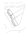
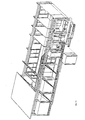
- Sheet 1 illustrates in extremely schematic form, in perspective, a dwelling consisting of two storeys in which the construction system is illustrated.
- the supporting structure comprises a number of columns which are provided with a number of cantilevers which project inwardly level with the floors.
- the mutual spacing between the columns is governed by the choice made by the purchasor of the dwelling concerning the arrangement of the house, particularly the dimensions of the purpose units in which the sanitary and other facilities are provided.
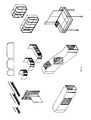
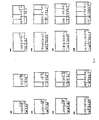
- Fig. 2 illustrates the possibilities which exist with regard to the purpose units, whereby the various dimensions can be regarded as terms from a FIBONACCI series.
- the same diagram illustrates a staircase element and a W.C. extending across two storeys.
- Fig. 2 The purpose elements shown in Fig. 2 are pre- fabricated in the factory. It is possible here to employ standard sanitary and piping material, together with standard kitchen units. Pre-fabrication extends up to the assembly and connection of all sub-components such as baths, shower trays etc. and the provision of wall apertures and pipe connections. As a result of the provision of wall apertures, the box-shaped purpose units which are produced otherwise from neutral standard components are provided with a demonstrable function, but if so these can be mounted at any point on the facades between two columns.
- the pipes of a purpose unit are provided upon a plate or pipe bulkhead, see Fig. 15. Assembly is undertaken by installing the corresponding bulkhead and fastening the pipes by means of quick release couplings or screwed couplings. If necessary this can also be carried out using hoses.
- the said pipes are designed for water, gas and sewage purposes. These are always located in the area reserved for this purpose directly underneath the purpose units.
- Fig. 15 likewise shows that at the side of or inside a technical purpose unit a shaft is provided on the vertical running of pipes and exhaust gases and for ventilation. This is the only point in the system where an aperture is made through a roof, which reduces the risk of leakage.
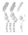
- Fig. 3 illustrates a number of auxiliary units which can be attached to the facade opposite the purpose units.
- auxiliary units can consist of a balcony, a bay window, a plant greenhouse, a porch, a corridor and/or staircase, a conservatory, a sun awning, a windshield, a terrace or a gallery.
- a hybrid solution is also feasible in which one of the facades is made up from purpose units and one or more auxiliary units.
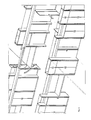
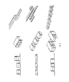
- the cupboards for the dwelling are accommodated in a boxed zone which is directed transverse to the floor sections, as can be seen in Fig. 4-7.
- This boxed zone also contains electrical and heating/ventilation facilities.
- the zone can be accessed and is exploitable from two sides.
- In these boxes there is a conductor duct located above door level so that no wall apertures are required. These conductors can be consequently included in the prefabrication stage.
- Fig. 4 between the boxes there is a conductor space which can be employed for connecting up plug sockets, switches and ventilation apertures.
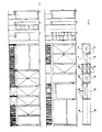
- FIG. 8 provides a schematic view of the floor widths to be employed and the construction of these floors from only two different types of floor components of differing widths, the dimensions of which comprise part of the FIBONACCI series which forms the basis of the dwelling concerned.
- Fig. 9 illustrates a number of embodiments of flat sites with the supporting structure employed here comprising four or five columns. This Fig. 9 illustrates how many variations are feasible in spite of the limited number of basic elements or purpose units which are available in prefabricated form.
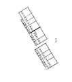
- Figs. 10 and 11 provide extremely schematic illustrations of fairly compact structures obtained using the system in accordance with the invention, i.e. a complete dwelling which is built up only from prefabricated components whilst retaining a very large range of variations which can be introduced without increasing costs.
- FIG. 12 provides a frontal view and a plan view
- Fig. 13 provides a more detailed perspective view in combination with a slightly sloping roof construction with ventilation facilities which has been employed.
- Fig. 14 again illustrates another embodiment of a dwelling consisting of two storeys whereby the top storey is provided with a great deal of balcony space.
- Fig. 15 provides a cut-away perspective view of a dwelling consisting of two storeys with a detailed representation of the sanitary facilities in the purpose units employed.
- Fig. 16 illustrates the design of a facade in which a large number of solar shelter elements are provided and where the technical purpose units are located on the rear facade face which is not illustrated.
Landscapes
- Engineering & Computer Science (AREA)
- Architecture (AREA)
- Civil Engineering (AREA)
- Structural Engineering (AREA)
- Physics & Mathematics (AREA)
- Electromagnetism (AREA)
- Load-Bearing And Curtain Walls (AREA)
- Floor Finish (AREA)
- Working Measures On Existing Buildindgs (AREA)
- Installation Of Indoor Wiring (AREA)
Claims (7)
Priority Applications (1)
| Application Number | Priority Date | Filing Date | Title |
|---|---|---|---|
| AT81201332T ATE14236T1 (de) | 1980-12-09 | 1981-12-09 | Hausbausystem und auf diese weise gebautes haus. |
Applications Claiming Priority (2)
| Application Number | Priority Date | Filing Date | Title |
|---|---|---|---|
| NL8006672 | 1980-12-09 | ||
| NL8006672A NL8006672A (nl) | 1980-12-09 | 1980-12-09 | Constructie systeem voor een behuizing, alsmede een aldus gebouwde behuizing. |
Publications (2)
| Publication Number | Publication Date |
|---|---|
| EP0053863A1 EP0053863A1 (fr) | 1982-06-16 |
| EP0053863B1 true EP0053863B1 (fr) | 1985-07-10 |
Family
ID=19836298
Family Applications (1)
| Application Number | Title | Priority Date | Filing Date |
|---|---|---|---|
| EP81201332A Expired EP0053863B1 (fr) | 1980-12-09 | 1981-12-09 | Système de construction pour maison et maison contruite selon ce système |
Country Status (4)
| Country | Link |
|---|---|
| EP (1) | EP0053863B1 (fr) |
| AT (1) | ATE14236T1 (fr) |
| DE (1) | DE3171350D1 (fr) |
| NL (1) | NL8006672A (fr) |
Families Citing this family (3)
| Publication number | Priority date | Publication date | Assignee | Title |
|---|---|---|---|---|
| FR2630486B1 (fr) * | 1988-04-21 | 1991-06-28 | Hypromat France | Procede d'edification rapide de station de lavage automatique a libre service pour vehicules automobiles |
| FR2665207B1 (fr) * | 1990-07-25 | 1992-10-09 | Ouabdesselam Cherif | Structure de gros-óoeuvre de maisons prefabriquees a murs exterieurs en dalles utilisant des tables a moules incorpores. |
| GB2263917B (en) * | 1991-10-17 | 1995-06-14 | Cherif Ouabdesselam | Prefabricated concrete panel and corner member outer wall building process featuring a dismountable multi-mold table |
Family Cites Families (5)
| Publication number | Priority date | Publication date | Assignee | Title |
|---|---|---|---|---|
| FR996664A (fr) * | 1945-05-15 | 1951-12-24 | Perfectionnements apportés aux ensembles à usage humain constitués par la juxtaposition d'éléments | |
| US3897662A (en) * | 1973-06-13 | 1975-08-05 | Miroslav Fencl | Coordinated modular building construction |
| FR2262176A1 (en) * | 1974-02-25 | 1975-09-19 | Mure Ste Gle Expl Commerciale | Modular holiday home construction system - has columns assembled by top and bottom cross-members |
| FR2263359A1 (en) * | 1974-03-08 | 1975-10-03 | Saint Arroman Jean | Separate and collective accommodation unit-system - consists of blocks containing installations and services |
| US4078342A (en) * | 1974-11-20 | 1978-03-14 | Cohen, Pesman, Zee, Ontwerp B.V. | Series of elements |
-
1980
- 1980-12-09 NL NL8006672A patent/NL8006672A/nl not_active Application Discontinuation
-
1981
- 1981-12-09 EP EP81201332A patent/EP0053863B1/fr not_active Expired
- 1981-12-09 DE DE8181201332T patent/DE3171350D1/de not_active Expired
- 1981-12-09 AT AT81201332T patent/ATE14236T1/de active
Also Published As
| Publication number | Publication date |
|---|---|
| ATE14236T1 (de) | 1985-07-15 |
| EP0053863A1 (fr) | 1982-06-16 |
| DE3171350D1 (en) | 1985-08-14 |
| NL8006672A (nl) | 1982-07-01 |
Similar Documents
| Publication | Publication Date | Title |
|---|---|---|
| US4513545A (en) | Apparatus for and method of constructing, transporting and erecting a structure of two or more stories comprised of a plurality of prefabricated core modules and panelized room elements | |
| US3762115A (en) | Multilevel concrete building of precast modular units | |
| US3638380A (en) | Modular high-rise structure | |
| US3643390A (en) | Modular building structure | |
| US5103604A (en) | Modular building systems | |
| US5491934A (en) | Two story building collapsed for shipping | |
| EP1908888A2 (fr) | Bâtiments modulaires | |
| DE102017125886A1 (de) | Raumzelle zur Verwendung bei der Errichtung von Gebäuden in Systembauweise | |
| US6457281B1 (en) | Modular building systems | |
| EP0053863B1 (fr) | Système de construction pour maison et maison contruite selon ce système | |
| WO2004048710A1 (fr) | Module de construction | |
| US3710521A (en) | Multistory buildings and walls thereof | |
| EP1196668B1 (fr) | Systeme de construction | |
| EP0043223B1 (fr) | Module de construction | |
| US4015377A (en) | Collapsible multilevel building | |
| US4202146A (en) | Transportable module for trilevel dwelling | |
| AU2008352422A1 (en) | A transportable building including a roof structure for stacking of multiple buildings | |
| DE19700302A1 (de) | Wohnhaus aus Fertigteilen | |
| DE102017125829A1 (de) | Verfahren zur Herstellung von Wandbauteilen für Gebäude | |
| DE102017125870A1 (de) | Verfahren zur Zusammenstellung von Wandbauteilen und Raumzellen zur Errichtung eines mehrgeschossigen Gebäudes | |
| JPS58218534A (ja) | 住居の構造様式 | |
| JPS6114299B2 (fr) | ||
| NL8300888A (nl) | Werkwijze voor het construeren van een gebouw, alsmede door toepassing van deze werkwijze geconstrueerd gebouw. | |
| RU2273701C2 (ru) | Способ сооружения зданий при помощи предварительно изготовленных элементов | |
| RU2048648C1 (ru) | Здание, секция здания (варианты) |
Legal Events
| Date | Code | Title | Description |
|---|---|---|---|
| PUAI | Public reference made under article 153(3) epc to a published international application that has entered the european phase |
Free format text: ORIGINAL CODE: 0009012 |
|
| AK | Designated contracting states |
Designated state(s): AT BE CH DE FR GB IT LI LU NL SE |
|
| 17P | Request for examination filed |
Effective date: 19821201 |
|
| ITF | It: translation for a ep patent filed |
Owner name: STUDIO GLP S.R.L. |
|
| GRAA | (expected) grant |
Free format text: ORIGINAL CODE: 0009210 |
|
| AK | Designated contracting states |
Designated state(s): AT BE CH DE FR GB IT LI LU NL SE |
|
| REF | Corresponds to: |
Ref document number: 14236 Country of ref document: AT Date of ref document: 19850715 Kind code of ref document: T |
|
| REF | Corresponds to: |
Ref document number: 3171350 Country of ref document: DE Date of ref document: 19850814 |
|
| ET | Fr: translation filed | ||
| PG25 | Lapsed in a contracting state [announced via postgrant information from national office to epo] |
Ref country code: AT Effective date: 19851209 |
|
| PG25 | Lapsed in a contracting state [announced via postgrant information from national office to epo] |
Ref country code: SE Effective date: 19851210 |
|
| PG25 | Lapsed in a contracting state [announced via postgrant information from national office to epo] |
Ref country code: LU Free format text: LAPSE BECAUSE OF NON-PAYMENT OF DUE FEES Effective date: 19851231 Ref country code: LI Effective date: 19851231 Ref country code: CH Effective date: 19851231 Ref country code: BE Effective date: 19851231 |
|
| PLBE | No opposition filed within time limit |
Free format text: ORIGINAL CODE: 0009261 |
|
| STAA | Information on the status of an ep patent application or granted ep patent |
Free format text: STATUS: NO OPPOSITION FILED WITHIN TIME LIMIT |
|
| BERE | Be: lapsed |
Owner name: HEIWO P.P.A. B.V. Effective date: 19851231 Owner name: COHEN PESMAN ZEE ONTWERP B.V. Effective date: 19851231 |
|
| PG25 | Lapsed in a contracting state [announced via postgrant information from national office to epo] |
Ref country code: NL Effective date: 19860701 |
|
| 26N | No opposition filed | ||
| GBPC | Gb: european patent ceased through non-payment of renewal fee | ||
| NLV4 | Nl: lapsed or anulled due to non-payment of the annual fee | ||
| PG25 | Lapsed in a contracting state [announced via postgrant information from national office to epo] |
Ref country code: FR Free format text: LAPSE BECAUSE OF NON-PAYMENT OF DUE FEES Effective date: 19860829 |
|
| REG | Reference to a national code |
Ref country code: CH Ref legal event code: PL |
|
| PG25 | Lapsed in a contracting state [announced via postgrant information from national office to epo] |
Ref country code: DE Effective date: 19860902 |
|
| REG | Reference to a national code |
Ref country code: FR Ref legal event code: ST |
|
| PG25 | Lapsed in a contracting state [announced via postgrant information from national office to epo] |
Ref country code: GB Effective date: 19881118 |
|
| EUG | Se: european patent has lapsed |
Ref document number: 81201332.4 Effective date: 19860902 |