EP0053485B1 - Dc permanent magnet motors - Google Patents
Dc permanent magnet motors Download PDFInfo
- Publication number
- EP0053485B1 EP0053485B1 EP81305594A EP81305594A EP0053485B1 EP 0053485 B1 EP0053485 B1 EP 0053485B1 EP 81305594 A EP81305594 A EP 81305594A EP 81305594 A EP81305594 A EP 81305594A EP 0053485 B1 EP0053485 B1 EP 0053485B1
- Authority
- EP
- European Patent Office
- Prior art keywords
- pole piece
- armature
- motor
- edges
- permanent magnet
- Prior art date
- Legal status (The legal status is an assumption and is not a legal conclusion. Google has not performed a legal analysis and makes no representation as to the accuracy of the status listed.)
- Expired
Links
- 238000013459 approach Methods 0.000 description 7
- 230000000694 effects Effects 0.000 description 4
- 239000004020 conductor Substances 0.000 description 3
- 238000004519 manufacturing process Methods 0.000 description 3
- 229910010293 ceramic material Inorganic materials 0.000 description 1
- 238000005520 cutting process Methods 0.000 description 1
- 230000007423 decrease Effects 0.000 description 1
- 230000002939 deleterious effect Effects 0.000 description 1
- 239000002184 metal Substances 0.000 description 1
- 230000002093 peripheral effect Effects 0.000 description 1
- 239000002002 slurry Substances 0.000 description 1
- 238000003892 spreading Methods 0.000 description 1
- 238000004804 winding Methods 0.000 description 1
- 229910000859 α-Fe Inorganic materials 0.000 description 1
Images

Classifications
-
- H—ELECTRICITY
- H02—GENERATION; CONVERSION OR DISTRIBUTION OF ELECTRIC POWER
- H02K—DYNAMO-ELECTRIC MACHINES
- H02K23/00—DC commutator motors or generators having mechanical commutator; Universal AC/DC commutator motors
- H02K23/02—DC commutator motors or generators having mechanical commutator; Universal AC/DC commutator motors characterised by arrangement for exciting
- H02K23/04—DC commutator motors or generators having mechanical commutator; Universal AC/DC commutator motors characterised by arrangement for exciting having permanent magnet excitation
-
- H—ELECTRICITY
- H02—GENERATION; CONVERSION OR DISTRIBUTION OF ELECTRIC POWER
- H02K—DYNAMO-ELECTRIC MACHINES
- H02K2201/00—Specific aspects not provided for in the other groups of this subclass relating to the magnetic circuits
- H02K2201/06—Magnetic cores, or permanent magnets characterised by their skew
Definitions
- This invention relates to direct current, permanent magnet motors.
- Direct current permanent magnet motors are used in a wide variety of applications including servo motor and other control applications.
- Such motors typically have two or more permanent magnet poles to create a magnet field and an armature rotatably mounted in the field.
- the armature has a series of bars or teeth evenly spaced around its periphery. Conductors wound in slots formed between the bars carry the energizing current for the motor.
- the armature of such motors is constructed from a series of discs or laminae stacked on a shaft.
- Cogging has two deleterious manifestations. One is a variable torque characteristic, and the other is a preferred stable positional relationship between the armature and the pole piece.
- An object of this invention is to provide a DC permanent magnet motor which does not have a tendency to cog, and can be manufactured economically.
- a DC permanent magnet motor comprising a permanent magnet pole piece in the shape of a cylindrical sector, and an armature rotatable in the cylinder with a series of armature bars around its periphery, the edges of the pole piece and the armature bars being so shaped and oriented as to reduce cogging, characterized in that the pole piece has, along both edges where the inner face and the end face meet, a series of notches which present alternately sloping edges to the armature bars passing them.
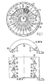
- a DC permanent magnet motor has a magnetically permeable housing 12 which supports a pair of partially cylindrical permanent field poles 14 and 16.
- a shaft 18 supports an armature 22 which has a series of uniformally spaced bars or teeth 24 distributed around its periphery.
- Electrical conductors 28, (only a few of which are shown in Figure 1 for the purposes of clarity) are wound in the troughs or slots between the bars 24. This winding is connected to commutator segments (not shown) to which energy is supplied by means of commutator brushes (not shown) in order to provide the electrical energy for driving the motor.
- the plates and bearings affixed to the housing 12 rotatably support the shaft 18 in axial alignment with the partially cylindrical pole pieces.
- the armature bars 24 rotate in close proximity to the field poles 14 and 16.
- the structural details for supporting the armature in relation to the field poles is well known in the art they have been omitted here for the sake of clarity.
- the DC permanent magnet motor thus far described is representative of conventional prior art motors.
- the torque produced by the magnetic attraction between the pole pieces 14 and 16, and the armature bars 24, varies rapidly as each armature bar approaches the edge of the permanent magnet pole piece.
- This variable torque produces the so called cogging effect.
- the attraction, and thus the torque, between a single lamina of the armature, and the pole piece is relatively small.
- each bar approaches the edge of the pole piece uniformally throughout its entire length, and the attraction between the pole piece and each lamina is accumulative. This results in a relatively large, sharply defined cogging torque.
- a series of cutouts or notches 32 are formed along longitudinal edges of the pole pieces 14 and 16; the two pole pieces are interchangeable. As will be described more fully below, the provision of these notches in the pole pieces substantially reduces and or eliminates cogging. It should be noted that the notched pole pieces can be used in place of conventional pole pieces in a wide variety of permanent magnet DC motors without materially altering the manufacturing procedures for such motors or materially adding to their cost.
- the length (L) of the notch measured from the edge of the inner curved surface of the pole piece in a circumferential direction, is substantially equal to the distance between the corresponding radially outermost points on adjacent armature bars (that is, the bar pitch). If the length of the notch is not equal to the bar pitch there will still be a reduction in cogging. However, in general the results will not be as good as where the length is equal to the bar pitch.
- the notch depth (D) and the notch width (W) are not critical and can be made any convenient dimension.
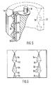
- the notches form a series of substantially straight alternately sloping edges 34 to form a zigzag pattern on the inner surface 35 of the pole piece, so that the effective overall length of the pole piece presented to an armature bar entering or leaving the inner surface of the pole piece increases or decreases linearly. If the edges are not straight there would still be a reduction in the cogging, however, in general the results would not be as satisfactory as if straight edges are used.
- the notches 34 need not be symmetrical (i.e. the shapes of the edge 34 need not be the same) as shown in Figures 2a and 2b. They may be sawtooth, for example, as shown in Figure 6. As illustrated in Figure 2b and Figure 6, it is not necessary that there be a full notch at either end of the pole piece, and if there is a partial notch at one end of the pole piece it is not necessary that there be the same partial notch at the other end of the pole piece. This aspect of the present motor provides certain important benefits.
- the pole pieces may be of metal and the notches 32 formed in any suitable manner known in the art, such as by cutting or grinding.
- the pole pieces may be of ceramic material and are made by starting with a ferrite slurry which is molded into a desired arc shape with the notches incorporated into the shape. It is convenient to mold such pole pieces in fairly long lengths, and then cut them to a length for a particular motor. Since it is not necessary that a full notch be at either end of the pole piece or that the partial notch at either end be the same, a single relatively long magnet can be molded, and then cut to any desired length.
Landscapes
- Engineering & Computer Science (AREA)
- Power Engineering (AREA)
- Dc Machiner (AREA)
Applications Claiming Priority (2)
| Application Number | Priority Date | Filing Date | Title |
|---|---|---|---|
| US211887 | 1980-12-01 | ||
| US06/211,887 US4341969A (en) | 1980-12-01 | 1980-12-01 | Direct current motor with improved pole piece that reduces cogging |
Publications (2)
| Publication Number | Publication Date |
|---|---|
| EP0053485A1 EP0053485A1 (en) | 1982-06-09 |
| EP0053485B1 true EP0053485B1 (en) | 1988-06-01 |
Family
ID=22788698
Family Applications (1)
| Application Number | Title | Priority Date | Filing Date |
|---|---|---|---|
| EP81305594A Expired EP0053485B1 (en) | 1980-12-01 | 1981-11-26 | Dc permanent magnet motors |
Country Status (6)
| Country | Link |
|---|---|
| US (1) | US4341969A (en:Method) |
| EP (1) | EP0053485B1 (en:Method) |
| JP (1) | JPS57173365A (en:Method) |
| AU (1) | AU554972B2 (en:Method) |
| CA (1) | CA1169906A (en:Method) |
| DE (1) | DE3176775D1 (en:Method) |
Families Citing this family (20)
| Publication number | Priority date | Publication date | Assignee | Title |
|---|---|---|---|---|
| US4797592A (en) * | 1982-06-17 | 1989-01-10 | Kollmorgen Technologies Corporation | Dynamo electric machine with upwardly shifted ripple frequency |
| US4593216A (en) * | 1982-09-24 | 1986-06-03 | Ibm Business Machines Corporation | Rotary stepping motor having improved construction |
| US5047682A (en) * | 1986-01-13 | 1991-09-10 | Papst-Motoren Gmbh & Co. Kg | Permanent magnet excited electric motor |
| EP0409661B1 (en) * | 1989-07-21 | 1995-01-11 | Mitsubishi Chemical Corporation | Motor |
| IT1261598B (it) | 1993-09-30 | 1996-05-23 | Gate Spa | Motore elettrico a magneti permanenti con coppia di riluttanza ridotta |
| US5753991A (en) * | 1994-12-02 | 1998-05-19 | Hydro-Quebec | Multiphase brushless AC electric machine |
| EP0748027B1 (en) * | 1995-06-07 | 2006-09-06 | General Electric Company | Dynamoelectric machine and rotor construction thereof |
| US5783890A (en) * | 1995-06-26 | 1998-07-21 | Cleveland Motion Controls, Inc. | Imprinted geometric magnetic anticog permanent magnet motor |
| US6166463A (en) * | 1998-11-25 | 2000-12-26 | Woodward, Jr.; Richard C. | Axial force electrical machines |
| US6204584B1 (en) | 2000-01-18 | 2001-03-20 | Cleveland Motion Controls, Inc. | Low cogging torque brushless motor rotor |
| US6713922B2 (en) * | 2000-12-29 | 2004-03-30 | Otis Elevator Company | Integrally skewed permanent magnet for use in an electric machine |
| JP4740480B2 (ja) * | 2001-06-29 | 2011-08-03 | アスモ株式会社 | 回転電機 |
| US6858960B1 (en) | 2002-09-17 | 2005-02-22 | Dana Corporation | Low cogging permanent magnet motor |
| JP3839428B2 (ja) * | 2003-06-10 | 2006-11-01 | アスモ株式会社 | 直流機 |
| JP2006086319A (ja) * | 2004-09-16 | 2006-03-30 | Mitsubishi Electric Corp | リング型焼結磁石 |
| JP4940872B2 (ja) * | 2006-10-03 | 2012-05-30 | 株式会社ジェイテクト | 電動モータのステータ、電動モータ、及び電動ポンプユニット |
| DE102006061628A1 (de) * | 2006-12-27 | 2008-07-03 | Robert Bosch Gmbh | Elektrische Maschine |
| NL2003978C2 (en) | 2008-12-19 | 2010-09-20 | Monsanto Invest Nv | Method of breeding cysdv-resistant cucumber plants. |
| CN107134865B (zh) * | 2017-05-15 | 2019-05-07 | 广东工业大学 | 一种确定永磁体削角的方法及装置 |
| CN115800567B (zh) * | 2022-11-23 | 2025-11-11 | 浙江联宜电机有限公司 | 直流有刷电机的磁钢结构及直流有刷电机 |
Family Cites Families (8)
| Publication number | Priority date | Publication date | Assignee | Title |
|---|---|---|---|---|
| DE436789C (de) * | 1926-11-09 | Siemens Schuckertwerke G M B H | Verfahren zur Herstellung von Einschnitten an den Polhoernern ungeblaetterter Magnetpole elektrischer Maschinen | |
| DE104021C (en:Method) * | ||||
| GB439439A (en) * | 1934-09-24 | 1935-12-06 | English Electric Co Ltd | Improvements in dynamo electric machines |
| GB1142591A (en) * | 1966-05-26 | 1969-02-12 | Gen Motors Ltd | Permanent magnet electric motors |
| FR2033663A5 (en:Method) * | 1969-02-25 | 1970-12-04 | Jammet Jean | |
| US3663851A (en) * | 1970-09-21 | 1972-05-16 | Electro Craft Corp | D.c. motor |
| JPS51113102U (en:Method) * | 1975-03-11 | 1976-09-13 | ||
| DE2558958A1 (de) * | 1975-12-29 | 1977-07-07 | Siemens Ag | Gleichstrommaschine |
-
1980
- 1980-12-01 US US06/211,887 patent/US4341969A/en not_active Expired - Lifetime
-
1981
- 1981-11-25 AU AU77852/81A patent/AU554972B2/en not_active Ceased
- 1981-11-26 EP EP81305594A patent/EP0053485B1/en not_active Expired
- 1981-11-26 DE DE8181305594T patent/DE3176775D1/de not_active Expired
- 1981-11-30 CA CA000391141A patent/CA1169906A/en not_active Expired
- 1981-12-01 JP JP56191881A patent/JPS57173365A/ja active Granted
Also Published As
| Publication number | Publication date |
|---|---|
| JPS57173365A (en) | 1982-10-25 |
| DE3176775D1 (en) | 1988-07-07 |
| JPH0373230B2 (en:Method) | 1991-11-21 |
| AU7785281A (en) | 1982-06-10 |
| US4341969A (en) | 1982-07-27 |
| EP0053485A1 (en) | 1982-06-09 |
| CA1169906A (en) | 1984-06-26 |
| AU554972B2 (en) | 1986-09-11 |
Similar Documents
| Publication | Publication Date | Title |
|---|---|---|
| EP0053485B1 (en) | Dc permanent magnet motors | |
| US4933584A (en) | Electronically commutated motor having skewed magnetics | |
| US4403161A (en) | Permanent magnet rotor | |
| US5783890A (en) | Imprinted geometric magnetic anticog permanent magnet motor | |
| EP0736232B1 (en) | Electrical machines | |
| US4053801A (en) | Armature structure for permanent magnet d-c motor | |
| US3842300A (en) | Laminated rotor structure for a dynamoelectric machine | |
| WO1998018189A3 (de) | Elektrische maschine mit einer einzelpolwicklung | |
| SE512783C2 (sv) | Statoraggregat för en elektrisk maskin | |
| GB2126433A (en) | Permanent magnet dc motor with magnets recessed into motor frame | |
| US3746900A (en) | Synchronous motor with improved starting characteristics | |
| US4605873A (en) | Electromechanical machine | |
| JPH05219706A (ja) | 永久磁石回転子を備えた電気機械 | |
| US4482832A (en) | Shaded pole motor lamination | |
| US4260926A (en) | Variable reluctance electric motor with progressively saturable poles | |
| US3949250A (en) | Rotary actuators | |
| USRE31950E (en) | Alternating current generators and motors | |
| US6617748B2 (en) | Machine with cup-shaped armature and air gap | |
| US6720697B2 (en) | Direct-current motor | |
| US4246504A (en) | Electric motors | |
| EP0016473B1 (en) | A direct current motor having e-shaped interpoles and main poles with unsymmetrical pole pieces | |
| JPS6019496Y2 (ja) | 回転電機の電機子 | |
| AU683174B2 (en) | DC magnetic motor assembly | |
| JPH0638500A (ja) | リニアモータ | |
| EP0170742B1 (en) | Permanent magnet type stepping motor |
Legal Events
| Date | Code | Title | Description |
|---|---|---|---|
| PUAI | Public reference made under article 153(3) epc to a published international application that has entered the european phase |
Free format text: ORIGINAL CODE: 0009012 |
|
| AK | Designated contracting states |
Designated state(s): DE GB SE |
|
| 17P | Request for examination filed |
Effective date: 19821115 |
|
| RAP1 | Party data changed (applicant data changed or rights of an application transferred) |
Owner name: PACIFIC SCIENTIFIC COMPANY |
|
| GRAA | (expected) grant |
Free format text: ORIGINAL CODE: 0009210 |
|
| AK | Designated contracting states |
Kind code of ref document: B1 Designated state(s): DE GB SE |
|
| REF | Corresponds to: |
Ref document number: 3176775 Country of ref document: DE Date of ref document: 19880707 |
|
| PG25 | Lapsed in a contracting state [announced via postgrant information from national office to epo] |
Ref country code: SE Effective date: 19881127 |
|
| PLBE | No opposition filed within time limit |
Free format text: ORIGINAL CODE: 0009261 |
|
| STAA | Information on the status of an ep patent application or granted ep patent |
Free format text: STATUS: NO OPPOSITION FILED WITHIN TIME LIMIT |
|
| 26N | No opposition filed | ||
| EUG | Se: european patent has lapsed |
Ref document number: 81305594.4 Effective date: 19890726 |
|
| PGFP | Annual fee paid to national office [announced via postgrant information from national office to epo] |
Ref country code: GB Payment date: 19991102 Year of fee payment: 19 Ref country code: DE Payment date: 19991102 Year of fee payment: 19 |
|
| PG25 | Lapsed in a contracting state [announced via postgrant information from national office to epo] |
Ref country code: GB Free format text: LAPSE BECAUSE OF NON-PAYMENT OF DUE FEES Effective date: 20001126 |
|
| GBPC | Gb: european patent ceased through non-payment of renewal fee |
Effective date: 20001126 |
|
| PG25 | Lapsed in a contracting state [announced via postgrant information from national office to epo] |
Ref country code: DE Free format text: LAPSE BECAUSE OF NON-PAYMENT OF DUE FEES Effective date: 20010801 |