EP0053340A2 - Sports shoe, in particular ski-boot - Google Patents
Sports shoe, in particular ski-boot Download PDFInfo
- Publication number
- EP0053340A2 EP0053340A2 EP81109827A EP81109827A EP0053340A2 EP 0053340 A2 EP0053340 A2 EP 0053340A2 EP 81109827 A EP81109827 A EP 81109827A EP 81109827 A EP81109827 A EP 81109827A EP 0053340 A2 EP0053340 A2 EP 0053340A2
- Authority
- EP
- European Patent Office
- Prior art keywords
- tongue
- sports shoe
- shoe according
- heel
- tongue part
- Prior art date
- Legal status (The legal status is an assumption and is not a legal conclusion. Google has not performed a legal analysis and makes no representation as to the accuracy of the status listed.)
- Withdrawn
Links
Images

Classifications
-
- A—HUMAN NECESSITIES
- A43—FOOTWEAR
- A43B—CHARACTERISTIC FEATURES OF FOOTWEAR; PARTS OF FOOTWEAR
- A43B5/00—Footwear for sporting purposes
- A43B5/04—Ski or like boots
-
- A—HUMAN NECESSITIES
- A43—FOOTWEAR
- A43B—CHARACTERISTIC FEATURES OF FOOTWEAR; PARTS OF FOOTWEAR
- A43B5/00—Footwear for sporting purposes
- A43B5/04—Ski or like boots
- A43B5/0427—Ski or like boots characterised by type or construction details
Definitions
- the present invention relates to a sports shoe, in particular a ski shoe, according to the preamble of claim 1.
- the transmission mechanism formed by the pull cable engages a tensioning element which crosses the instep area of the foot and runs on the inside of the shell part and on the foot or the Liner lies on.
- the pulling force exerted on the tensioning element when the heel part is folded up can now be changed by means of an adjusting device acting on the pulling cable and fastened to the heel part. In this way, an adaptation to the foot anatomy of the wearer is possible in that the foot is pulled more strongly backwards against the heel area of the shoe by adjusting the height of the anchoring point of the pull cable.
- This space not only has a disadvantageous effect on the power transmission between the foot and the shell part or ski, but also promotes the undesired bulging of the shell part when driving.
- the present invention aims to overcome the drawbacks mentioned above. It is therefore the task of creating a sports shoe of the type mentioned at the outset, which allows comfortable and rapid getting on and off, and in which, when closed, at all times, in particular also when driving, good contact everywhere between the shell part and the foot or the inner shoe is ensured. According to the invention, this object is achieved by the features of the characterizing part of claim 1.
- the coupling of the heel part with the tongue part by means of the transmission mechanism enables the shoe to be opened and closed easily, since a pivoting movement of the heel or tongue part inevitably results in a corresponding pivoting movement of the other part.
- the tongue part has an instep area and a section covering a subsequent shin area, a particularly effective lateral closing becomes effective when the heel part swivels forward Squeezing the shell part causes especially when the transmission mechanism acts on the transition between the instep and shin section of the tongue part.
- the force which the tongue part exerts on the shell part when the heel part is pivoted up can be changed. This allows adaptation to different foot sizes by more or less strong lateral compression of the shell part without losing contact between the foot or inner shoe and the shell part.
- the ski boot shown in the figures and designated 1 has a relatively stiff shell part 2 encompassing the lower foot area with a sole 3, a tongue part 4 covering the instep-shin area and a heel part 5 supporting the heel-calf area.
- the space between the shoe 1 and the foot of the wearer is filled in a manner known per se by a soft, padded inner shoe 6.
- the latter has on its front a cutout, not shown in the figures, which is closed by the tongue part 4.
- the tongue part 4 is connected to the shell part 2 in the region of its tip by means of a fastening element 7.
- This fastening element 7 allows, on the one hand, a pivoting of the tongue part 4 about an essentially horizontal axis 8 and a displacement of this tongue part 4 in the direction of arrow A, i.e. in the longitudinal direction of the shoe 1.
- the heel part 5 is fastened to the shell part 2 so as to be pivotable about a pivot axis which runs horizontally and lies approximately at the height of the heel bone.
- the lower side tabs 9 of the heel part 5, which lie on the outside of the shell part 2, are connected to the shell part 2 by means of swivel joints 10, which lie opposite one another with respect to the longitudinal center plane of the shoe 1.
- the upper side tabs 11 of the heel part 5, which covers a cutout in the shell part 2, not shown in the figures, come under the sides when the ski boot is closed overlap 12 of the shell part 2 to lie, as can be seen in particular from FIGS. 1 and 3 to 6.
- the side parts of the heel part thus run through a scissor-like intersection 13 in the shell part 2.
- a latch adjustment mechanism 14 is arranged approximately halfway up, which can be actuated from the outside and has a fastening element 15 which is arranged on the inside of the heel part 5 and which is adjustable in height.
- Two steel cables 16 which run symmetrically with respect to the longitudinal center plane of the shoe 1 are fastened to this fastening element 15, which run downwards on the inside of the shoe 1 to a deflection point 17 and from there in the direction towards the swivel joints 10.
- the steel cables 16 are each guided through a tube 18 which is embedded in the surface of the shell part 2 running along the heel line. In the area of the swivel joints 10, the steel cables 16 are connected to the one end of a thin steel strip 19.
- the two steel strips 19 are also arranged symmetrically with respect to the longitudinal center plane of the shoe 1 and anchored at the instep of the instep on the side tabs of the tongue part 4 by means of joints 20.
- the steel bands 19 pass through slots 21 in the shell part 2 into the interior of the shoe and run in the direction against the swivel joints 10.
- the steel bands 19 are provided with an elongated hole 22 into which the pivot pin 10a of the associated swivel joint 10 engages. In this way, the steel strips 19 are guided longitudinally and can move in the direction of the arrow B (FIG. 2).
- the tongue part 4 is coupled to the heel part 5 via the steel cables 16 and the steel bands 19 such that a pivoting movement of the heel part 5 inevitably results in a corresponding pivoting movement of the tongue part 4 and vice versa. If the tongue part 4 is pivoted forward, the heel part 5 pivots accordingly to the rear. A pivoting of the heel part 5 to the front results in a movement of the tongue part 4 to the rear in the direction of action B of the transmission mechanism 16, 19.
- a twist lock 23 of a known type is attached to the heel part 5 above the locking mechanism 14.
- Two connecting straps 24 extend from this rotary closure 23 and extend towards the tongue part 4 on opposite sides. At their free end, at which they are provided with teeth 25, the connecting straps 24 engage in holding elements 26 which are fastened to the tongue part 4. These holding elements 26 hold the connecting straps 24 firmly by means of a locking action.
- the ski boot 1 is opened by pivoting the heel part 5 to the rear, as shown in FIG. 2.
- the heel part 5 is now pivoted forward.
- the connecting straps 24 slide along the shell part 2 and engage in the holding elements 26. Tongue part 4 and heel part 5 are releasably held together in this way.
- the connecting straps 24 can be shortened or lengthened by means of the twist lock 23, so that when the ski boot 1 is closed (FIG. 1), it can be easily adapted to the wearer's leg width.
- the shoe 1 can be easily opened by loosening the connecting straps 24 in order to allow a relaxed, upright leg position when walking and standing.
- the connecting straps 24 can be released either by means of the twist lock 23 or by adjusting the connecting straps 24 in the holding elements 26.
- the tongue part 4 becomes in the effective direction B.
- Steel straps 19 pulled backwards. Since, as already mentioned, the tongue part 4 rests on the shell part 2 in a saddle-like manner, this is laterally compressed by the tongue part 4, as a result of which the foot is held in the shoe 1.
- the good contact between the foot and the ski boot 1 is also ensured at all times when driving, since when the lower leg is bent forward, the heel part 5 also performs a forward pivoting movement, as shown in FIG. 3.
- the connecting straps 24 are released by opening the holding elements 26.
- the heel part 5 is then pivoted directly or by lifting the tongue part 4 from the shell part 2 backwards into the position shown in FIG. 2.
- the force with which the tongue part 4 is pulled backwards when the ski boot 1 is closed can be adjusted.
- the amount by which the shell part 2 is compressed laterally when the ski boot is closed can be adapted to the anatomy of the wearer's foot. A perfect fit of each foot in the ski boot 1 can thus be achieved in a simple manner.
- the two ski boots shown in FIGS. 5 and 6 are constructed the same as the ski boot shown in FIGS. 1 to 4, with the exception of the tongue part 4.
- the tongue part 4 is elastically deformable in its longitudinal direction.
- the tongue part 4 has a wavy profile, as is known per se (published international application WO 81/00507). Due to the transverse elevations 27, the tongue part 4 is stiffened in the transverse direction, which largely prevents the tongue part 4 from being pushed apart while driving.
- the wave-shaped design of the tongue part 4 gives it a high resilience after deformation in its longitudinal direction. It is thereby achieved that a controlled rotational movement takes place around the swivel joints 10 or the ankle joint in the case of original movements.
- inserts 28 are used in the tongue part 4, which are made of a material with rubber-elastic properties and have an H-shaped profile (FIG. 7).
- the resilience properties of the tongue part 4 can be controlled in a targeted manner by using inserts with different elastic properties.
- FIG. 8 differs from the ski boot according to FIGS. 1 and 2 in that the upper part 2b of the shell part 2, i.e. the side tab 12 is articulated to the lower part 2a of the shell part 2.
- the articulation points 29 of the upper shell part 2b on the lower shell part 2a lie opposite one another with respect to the longitudinal center plane of the shoe 1 and are arranged in the region of the ankle.
- the upper shell part 2b is also articulated to the lower shell part 2a at the articulation points 29, as has already been described with reference to FIG. 8.
- the steel cables 16 are not connected to a locking mechanism 14, but to a tensioning mechanism 30.
- the steel strips 19 are omitted in this embodiment, so that the steel cables 16 are connected directly to the tongue part 4 at the fastening points 20.
- the tensioning mechanism 30 has a two-armed lever 31, which is articulated at the pivot point designated 31a to a connecting element 32 which is fastened to the heel part 5.
- a connecting element 32 which is fastened to the heel part 5.
- two screw spindles 33 On one arm of the lever 31, two screw spindles 33, of which only one is visible in FIG. 9, are attached in a rotatable and articulated manner.
- the steel cables 16 are anchored to a fastening element 34 which is in engagement with the one screw spindle 33 and is guided through the other screw spindle. With the latter, a further fastening element 35 is in screw engagement, which in turn is guided through the first-mentioned screw spindle.
- the ends of a steel cable are on the fastening element 35 36 attached, which is guided symmetrically with respect to the longitudinal center plane of the shoe 1.
- the cable 36 passes from the fastening element 35 through the heel part 5 and runs with the exception of loops 37 on the inside of the heel part 5.
- the cable loops 37 are suspended in a retaining hook 38 on the tongue part 4.
- the shoe according to FIG. 9 largely corresponds to the exemplary embodiments according to FIGS. 1 to 8.
- the fastening element 34 or the fastening element 35 can be adjusted, as a result of which the force with which the tongue part 4 and the heel part 5 are contracted when the ski boot is closed can be adjusted.
- certain parts of the ski boots can be designed differently than described.
- another type of fastening is also possible, which enables a corresponding movement of the tongue part 4 to the rear when the heel part 5 is pivoted up.
- a differently designed adjustment mechanism can also be used, as is shown, for example, in the already mentioned DE-OSs 27 12 001 and 28 05 943.
- tongue part 4 and heel part 5 can be connected in another suitable manner when the ski boot is closed.
Landscapes
- Health & Medical Sciences (AREA)
- General Health & Medical Sciences (AREA)
- Physical Education & Sports Medicine (AREA)
- Footwear And Its Accessory, Manufacturing Method And Apparatuses (AREA)
Abstract
Am Schalenteil (2) ist mittels Drehgelenken (10) ein Fersenteil (5) angelenkt. An diesem Fersenteil (5) ist ein Rastverstellmechanismus (14) angebracht, mittels dem ein Befestigungselement (15) in der Höhe verstellbar ist. An diesem Befestigungselement (15) sind zwei seitlich des Schuhs (1) verlaufende Kabel (16) verankert, die über eine Umlenkstelle (17) geführt sind und zu den Drehgelenken (10) hin verlaufen. Jedes Kabel (16) ist an einem Band (19) befestigt, das mittels eines Gelenkes (20) mit einem Zungenteil (4) verbunden ist. Dieser Zungenteil (4) übergreift sattelartig den Schalenteil (2) und ist mit diesem sowohl um eine horizontale Achse (8) schwenkbar wie auch in Schuhlängsrichtung (A) verschiebbar verbunden. Mittels eines Schließmechanismus (23 bis 26) sind Zungenteil (4) und Fersenteil (5) bei geschlossenem Skischuh (1) miteinander verbindbar. Über die Kabel (16) und die Bänder (19) wird eine Schwenkbewegung des Fersenteils (5) auf den Zungenteil (4) übertragen und umgekehrt. Beim Hochklappen des Fersenteils (5) in seine Schließstellung wird daher der Zungenteil (4) nach hinten gezogen. Das hat ein seitliches Zusammendrücken des Schalenteils (2) zur Folge, wodurch ein guter Sitz des Fußes im Skischuh erzielt wird. Dieser gute Sitz wird auch bei einer Vorlagebewegung während des Fahrens sichergestellt.
Description
Die vorliegende Erfindung betrifft einen Sportschuh, insbesondere einen Skischuh, gemäss Oberbegriff des Anspruches 1.The present invention relates to a sports shoe, in particular a ski shoe, according to the preamble of
Bei derartigen Skischuhen, wie sie beispielsweise aus den DE-OSen 27.12 001 und 28 05 943 bekannt sind, greift der durch Zugkabel gebildete Uebertragungsmechanismus an einem die Ristpartie des Fusses übergreifenden Spannelement an, das auf der Innenseite des Schalenteils verläuft und auf dem Fuss oder dem Innenschuh aufliegt. Mittels einer an den Zugkabeln angreifenden, am Fersenteil befestigten Verstelleinrichtung kann nun die bei hochgeklapptem Fersenteil auf das Spannelement ausgeübte Zugkraft verändert werden. Auf diese Weise ist eine Anpassung an die Fussanatomie des Trägers möglich, indem durch Höhenverstellung der Verankerungsstelle der Zugkabel der Fuss durch das Spannelement stärker nach hinten gegen den Fersenbereich des Schuhs gezogen wird. Das hat jedoch den Nachteil, dass dadurch je nach Grösse des Fusses zwischen diesem bzw. dem Innenschuh und dem unverändert bleibenden Schalenteil ein mehr oder weniger grosser Zwischenraum geschaffen wird. Damit geht jedoch der gewünschte direkte Kontakt zwischen Fuss bzw. Innenschuh und Schalenteil im Bereich dessen Vorderseite verloren. Dieser Zwischenraum wird beim Fahren zudem noch vergrössert, da beim Beugen des Unterschenkels der Fersenteil ebenfalls nach vorn verschwenkt wird, was einen noch stärkeren, nach hinten gerichteten Zug auf den Fuss zur Folge hat.In such ski boots, as are known, for example, from DE-OSes 27.12 001 and 28 05 943, the transmission mechanism formed by the pull cable engages a tensioning element which crosses the instep area of the foot and runs on the inside of the shell part and on the foot or the Liner lies on. The pulling force exerted on the tensioning element when the heel part is folded up can now be changed by means of an adjusting device acting on the pulling cable and fastened to the heel part. In this way, an adaptation to the foot anatomy of the wearer is possible in that the foot is pulled more strongly backwards against the heel area of the shoe by adjusting the height of the anchoring point of the pull cable. However, this has the disadvantage that, depending on the size of the foot, a more or less large space is created between this or the inner shoe and the shell part that remains unchanged. However, this means that the desired direct contact between the foot or liner and the shell part in the region of the front is lost. This gap is also increased when driving, because when the lower leg is bent, the heel part is also pivoted forward, which results in an even stronger rearward pull on the foot.
Dieser Zwischenraum wirkt sich nicht nur nachteilig auf die Kraftübertragung zwischen Fuss und Schalenteil bzw. Ski aus, sondern fördert zudem noch das unerwünschte Ausbuchten des Schalenteils beim Fahren.This space not only has a disadvantageous effect on the power transmission between the foot and the shell part or ski, but also promotes the undesired bulging of the shell part when driving.
Die vorliegende Erfindung bezweckt, die vorstehend erwähnten Nachteile zu beseitigen. Es stellt sich somit die Aufgabe, einen Sportschuh der eingangs genannten Art zu schaffen, der ein bequemes und rasches Ein- und Aussteigen erlaubt und bei dem im geschlossenen Zustand jederzeit, insbesondere auch beim Fahren, überall ein guter Kontakt zwischen dem Schalenteil und dem Fuss bzw. dem Innenschuh sichergestellt ist. Diese Aufgabe wird erfindungsgemäss durch die Merkmale des kennzeichnenden Teils des Anspruches 1 gelöst.The present invention aims to overcome the drawbacks mentioned above. It is therefore the task of creating a sports shoe of the type mentioned at the outset, which allows comfortable and rapid getting on and off, and in which, when closed, at all times, in particular also when driving, good contact everywhere between the shell part and the foot or the inner shoe is ensured. According to the invention, this object is achieved by the features of the characterizing part of
Beim Beugen des Unterschenkels und der dadurch bewirkten entsprechenden Schwenkbewegung des Fersenteils nach vorn wird der den Schalenteil sattelartig übergreifende Zungenteil gegen den Fersenteil gezogen, was ein seitliches Zusammendrücken des Schalenteils durch den Zungenteil zur Folge hat. Dadurch wird der Fuss, welcher bei einer solchen Vorlagebewegung die Tendenz hat, sich mit der Ferse abzuheben, noch fester im Schuh gehalten. Zudem wird ein Ausbauchen des Schalenteils vermieden.When the lower leg is bent and the corresponding pivoting movement of the heel part to the front is caused, the tongue part that engages over the saddle part is pulled against the heel part, which results in the side part of the shell part being compressed by the tongue part. As a result, the foot, which has the tendency to lift off with the heel during such an original movement, is held even more firmly in the shoe. Bulging of the shell part is also avoided.
Die Kupplung des Fersenteils mit dem Zungenteil mittels des Uebertragungsmechanismus ermöglicht ein leichtes Oeffnen und Schliessen des Schuhs, da eine Schwenkbewegung des Fersen- oder Zungenteils zwangsläufig eine entsprechende Schwenkbewegung des andern Teils zur Folge hat.The coupling of the heel part with the tongue part by means of the transmission mechanism enables the shoe to be opened and closed easily, since a pivoting movement of the heel or tongue part inevitably results in a corresponding pivoting movement of the other part.
Weist der Zungenteil einen den Ristbereich und einen, einen anschliessenden Schienbeinbereich überdeckenden Abschnitt auf, so wird bei einer Schwenkbewegung des Fersenteils nach vorn ein besonders wirkungsvolles seitliches Zusammendrücken des Schalenteils bewirkt insbesondere dann, wenn der Uebertragungsmechanismus am Uebergang zwischen Rist- und Schienbeinabschnitt des Zungenteils angreift.If the tongue part has an instep area and a section covering a subsequent shin area, a particularly effective lateral closing becomes effective when the heel part swivels forward Squeezing the shell part causes especially when the transmission mechanism acts on the transition between the instep and shin section of the tongue part.
Durch Vorsehen einer auf den Uebertragungsmechanismus einwirkenden Verstelleinrichtung kann die Kraft, die der Zungenteil bei hochgeschwenktem Fersenteil auf den Schalenteil ausübt, verändert werden. Dadurch ist ohne Verlust des Kontaktes zwischen Fuss bzw. Innenschuh und Schalenteil eine Anpassung an verschiedene Fussgrössen durch mehr oder weniger starkes seitliches Zusammendrücken des Schalenteiles möglich.By providing an adjusting device acting on the transmission mechanism, the force which the tongue part exerts on the shell part when the heel part is pivoted up can be changed. This allows adaptation to different foot sizes by more or less strong lateral compression of the shell part without losing contact between the foot or inner shoe and the shell part.
Weitere bevorzugte Ausführungsformen des erfindungsgemässen Sportschuhs bilden Gegenstand der übrigen abhängigen Ansprüche.Further preferred embodiments of the sports shoe according to the invention form the subject of the remaining dependent claims.
Im folgenden werden anhand der Zeichnungen Ausführungsbeispiele des Erfindungsgegenstandes näher erläutert. Es zeigen rein schematisch:
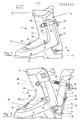
- Fig. 1 und 2 in Seitenansicht einen Skischuh in geschlossenem, fahrbereitem bzw. in geöffnetem, einstiegbereitem Zustand,
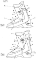
- Fig. 3 in Seitenansicht den geschlossenen Skischuh gemäss Fig. 1 in Vorlagestellung,
- Fig. 4 eine seitliche Ansicht des halbgeöffneten Skischuhs gemäss den Fig. 1 und 2,
- Fig. 5 und 6 Varianten des Skischuhs gemäss den Fig. 1 und 2 mit in Längsrichtung elastisch nachgiebigem Zungenteil,
- Fig. 7 einen bei der Ausführungsform gemäss Fig. 6 verwendeten Einsatz für den Zungenteil im Querschnitt, und
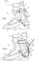
- Fig. 8 und 9 weitere Varianten des Skischuhs gemäss den Fig. 1 und 2.
- 1 and 2 in side view of a ski boot in the closed, ready to drive or in the open, ready-to-go state,
- 3 is a side view of the closed ski boot according to FIG. 1 in the template position,
- 4 shows a side view of the half-opened ski boot according to FIGS. 1 and 2,
- 5 and 6 variants of the ski boot according to FIGS. 1 and 2 with tongue part elastically resilient in the longitudinal direction,
- 7 shows an insert used in the embodiment according to FIG. 6 for the tongue part in cross section, and
- 8 and 9 further variants of the ski boot according to FIGS. 1 and 2.
Der in den Figuren dargestellte und mit 1 bezeichnete Skischuh weist einen den untern Fussbereich umfassenden, verhältnismässig steifen Schalenteil 2 mit einer Sohle 3, einen den Rist-Schienbein-Bereich überdeckenden Zungenteil 4 sowie einen den Fersen-Waden-Bereich stützenden Fersenteil 5 auf. Der Zwischenraum zwischen dem Schuh 1 und dem Fuss des Trägers wird auf an sich bekannte Weise durch einen weichen, gepolsterten Innenschuh 6 ausgefüllt Der Zungenteil 4, der einen den Ristbereich überdeckenden Abschnitt 4a und einen, den untern Schienenbeinbereich überdeckenden Abschnitt 4b aufweist, übergreift sattelartig den Schalenteil 2. Letzterer weist auf seiner Vorderseite einen in den Figuren nicht gezeigten Ausschnitt auf, der durch den Zungenteil 4 verschlossen wird. Wie die Fig. 2 zeigt, ist der Zungenteil 4 im Bereich seiner Spitze mittels eines Befestigungselementes 7 mit dem Schalenteil 2 verbunden. Dieses Befestigungselement 7 erlaubt auf bekannte Weise einerseits ein Verschwenken des Zungenteiles 4 um eine im wesentlichen horizontale Achse 8 sowie eine Verschiebung dieses Zungenteiles 4 in Richtung des Pfeiles A, d.h. in Längsrichtung des Schuhs 1.The ski boot shown in the figures and designated 1 has a relatively
Der Fersenteil 5 ist um eine horizontal verlaufende und ungefähr in der Höhe des Fersenbeins liegende Schwenkachse schwenkbar am Schalenteil 2 befestigt.The
Zu diesem Zweck sind die untern Seitenlappen 9 des Fersenteils 5, welche auf der Aussenseite des Schalenteiles 2 liegen, mittels Drehgelenken 10, welche sich bezüglich der Längsmittelebene des Schuhs 1 gegenüberliegen, mit dem Schalenteil 2 verbunden. Die obern Seitenlappen 11 des Fersenteiles 5, der einen in den Figuren nicht gezeigten Ausschnitt im Schalenteil 2 überdeckt, kommen bei geschlossenem Skischuh unter die Seitenlappen 12 des Schalenteiles 2 zu liegen, wie das insbesondere aus den Fig. 1 und 3 bis 6 hervorgeht. Die Seitenteile des Fersenteils verlaufen somit durch eine scherenartige Verschneidung 13 im Schalenteil 2 hindurch. Auf der Hinterseite des Fersenteils 5 ist etwa in halber Höhe ein Rastverstellmechanismus 14 angeordnet, der von aussen betätigbar ist und ein auf der Innenseite des Fersenteils 5 angeordnetes Befestigungselement 15 aufweist, das höhenverstellbar ist. An diesem Befestigungselement 15 sind zwei bezüglich der Längsmittelebene des Schuhs 1 symmetrisch verlaufende Stahlkabel 16 befestigt, die auf der Innenseite des Schuhs 1 nach unten zu einer Umlenkstelle 17 und von dieser in Richtung gegen die Drehgelenke 10 verlaufen. Die Stahlkabel 16 werden an dieser Umlenkstelle 17 durch jeweils ein Röhrchen 18 geführt, das entlang der Fersenlinie verlaufend in die Oberfläche des Schalenteils 2 eingelassen ist. Im Bereich der Drehgelenke 10 sind die Stahlkabel 16 mit dem einen Ende jeweils eines dünnen Stahlbandes 19 verbunden. Die beiden Stahlbänder 19 sind ebenfalls bezüglich der Längsmittelebene des Schuhs 1 symmetrisch angeordnet und in der Höhe der Ristbeuge an den Seitenlappen des Zungenteiles 4 mittels Gelenken 20 verankert. Die Stahlbänder 19 treten durch Schlitze 21 im Schalenteil 2 ins Innere des Schuhs und verlaufen in Richtung gegen die Drehgelenke 10. Die Stahlbänder 19 sind mit einem Langloch 22 versehen, in das der Drehzapfen 10a des zugeordneten Drehgelenkes 10 einqreift. Auf diese Weise sind die Stahlbänder 19 längsgeführt und können sich in Richtung des Pfeiles B (Fig. 2) bewegen.For this purpose, the
Ueber die Stahlkabel 16 und die Stahlbänder 19 ist der Zungenteil 4 mit dem Fersenteil 5 derart gekoppelt, dass eine Schwenkbewegung des Fersenteils 5 zwangsläufig eine entsprechende Schwenkbewegung des Zungenteils 4 und umgekehrt zur Folge hat. Wird der Zungenteil 4 nach vorn verschwenkt, so verschwenkt sich der Fersenteil 5 entsprechend nach hinten. Ein Verschwenken des Fersenteils 5 nach vorn hat eine Bewegung des Zungenteiles 4 nach hinten in Wirkrichtung B des Uebertragungsmechanismus 16, 19 zur Folge.The
Oberhalb des Rastverstellmechanismus 14 ist am Fersenteil 5 ein Drehverschluss 23 bekannter Bauart befestigt. Von diesem Drehverschluss 23 gehen zwei Verbindungsriemen 24 aus, die sich auf gegenüberliegenden Seiten nach vorn zum Zungenteil 4 hin erstrecken. An ihrem freien Ende, an dem sie mit einer Zahnung 25 versehen sind, greifen die Verbindungsriemen 24 in Halteelemente 26 ein, die am Zungenteil 4 befestigt sind. Diese Halteelemente 26 halten die Verbindungsriemen 24 durch Rastwirkung fest.A
Zum Einsteigen wird der Skischuh 1 durch Verschwenken des Fersenteiles 5 nach hinten geöffnet, wie das in Fig. 2 dargestellt ist. Zum Schliessen des Skischuhs 1 wird nun der Fersenteil 5 nach vorne verschwenkt. Dabei gleiten die Verbindungsriemen 24 entlang des Schalenteiles 2 und rasten in die Halteelemente 26 ein. Zungenteil 4 und Fersenteil 5 werden auf diese Weise lösbar zusammengehalten. Mittels des Drehverschlusses 23 können die Verbindungsriemen 24 verkürzt oder verlängert werden., wodurch bei geschlossenem Skischuh 1 (Fig. 1) auf einfache Weise eine Anpassung an die Beinweite des Trägers vorgenommen werden kann. Wie die Fig. 4 zeigt, lässt sich durch Lösen der Verbindungsriemen 24 der Schuh 1 leicht öffnen, um beim Gehen und Stehen eine entspannte, aufrechte Beinstellung zu ermöglichen. Das Lösen der Verbindungsriemen 24 kann entweder mittels des Drehverschlusses 23 oder durch Verstellen der Verbindungsriemen 24 in den Halteelementen26 erfolgen.To get in, the
Wie bereits erwähnt, wird durch das Schwenken des Fersenteils 5 nach vorne der Zungenteil 4 in Wirkrichtung B der Stahlbänder 19 nach hinten gezogen. Da der Zungenteil 4 wie bereits erwähnt sattelartig auf dem Schalenteil 2 aufliegt, so wird diese durch den Zungenteil 4 seitlich zusammengedrückt, wodurch der Fuss im Schuh 1 festgehalten wird. Zwischen dem Schuh 1 und dem Fuss bzw. dem Innenschuh 6 findet an allen Stellen eine Berührung statt, welche Gewähr für eine einwandfreie Kraftübertragung zwischen dem Fuss und dem Skischuh 1 bzw. dem Ski bietet. Der gute Kontakt zwischen dem Fuss und dem Skischuh 1 ist auch beim Fahren jederzeit sichergestellt, da bei einer Beugung des Unterschenkels nach vorn der Fersenteil 5 ebenfalls eine Schwenkbewegung nach vorn ausführt, wie das in Fig. 3 dargestellt ist. Durch diese Schwenkbewegung des Fersenteiles 5 wird der Zungenteil 4 noch stärker nach hinten gezogen, wodurch der Schalenteil 2 noch mehr zusammengedrückt wird. Somit wird der Fuss in dem Moment, in dem sich bei einer Vorlagebewegung die Ferse anzuheben beginnt, infolge des Zusammendrückens des Schalenteiles 2 unten gehalten, wodurch ein Abheben der Ferse und ein Ausbuchten des Schalenteiles 2 vermieden wird.As already mentioned, by pivoting the
Zum Aussteigen aus dem Skischuh werden die Verbindungsriemen 24 durch Oeffnen der Halteelemente 26 gelöst. Anschliessend wird der Fersenteil 5 direkt oder durch Abheben des Zungenteiles 4 vom Schalenteil 2 nach hinten in die in Fig. 2 gezeigte Stellung verschwenkt.To get out of the ski boot, the connecting
Mittels des Rastverstellmechanismus 14 kann die Kraft, mit welcher der Zungenteil 4 bei geschlossenem Skischuh 1 nach hinten gezogen wird, eingestellt werden. Auf diese Weise lässt sich das Mass, um welches der Schalenteil 2 bei geschlossenem Skischuh seitlich zusammengedrückt wird, an die Anatomie des Fusses des Trägers anpassen. Somit kann auf einfache Weise ein einwandfreier Sitz jedes Fusses im Skischuh 1 erzielt werden.By means of the locking
Die beiden in den Fig. 5 und 6 dargestellten Skischuhe sind mit Ausnahme des Zungenteiles 4 gleich aufgebaut wie der in den Fig. 1 bis 4 gezeigte Skischuh. Bei den in den Fig. 5 und 6 gezeigten Varianten ist der Zungenteil 4 in seiner Längsrichtung elastisch deformierbar.The two ski boots shown in FIGS. 5 and 6 are constructed the same as the ski boot shown in FIGS. 1 to 4, with the exception of the
Beim Skischuh gemäss Fig. 5 weist der Zungenteil 4 ein wellenförmiges Profil auf, wie das an sich bekannt ist (veröffentlichte internationale Anmeldung WO 81/00507). Durch die querverlaufenden Erhebungen 27 wird der Zungenteil 4 in Querrichtung versteift, wodurch ein Auseinanderdrücken des Zungenteiles 4 während des Fahrens weitgehend vermieden wird. Durch die wellenförmige Ausbildung des Zungenteiles 4 wird diesem nach einer Deformation in seiner Längsrichtung ein hohes Rückstellvermögen erteilt. Damit wird erreicht, dass bei Vorlagebewegungen eine kontrollierte Rotationsbewegung um die Drehgelenke 10 bzw. das Sprunggelenk stattfindet.5, the
Bei der Ausführungsform gemäss Fig. 6 sind in den Zungenteil 4 Einsätze 28 eingesetzt, die aus einem Material mit gummielastischen Eigenschaften bestehen und ein H-förmiges Profil (Fig. 7) aufweisen. Durch Verwendung von Einsätzen mit unterschiedlichen elastischen Eigenschaften lassen sich die Rückfederungseigenschaften des Zungenteiles 4 gezielt steuern.In the embodiment according to FIG. 6, inserts 28 are used in the
Die in der Fig. 8 gezeigte Ausführungsform unterscheidet sich vom Skischuh gemäss den Fig. 1 und 2 dadurch, dass der Oberteil 2b des Schalenteils 2, d.h. die Seitenlappen 12, gelenkig mit dem Unterteil 2a des Schalenteils 2 verbunden ist. Die Anlenkstellen 29 des Schalenoberteils 2b am Schalenunterteil 2a liegen sich bezüglich der Längsmittelebene des Schuhs 1 gegenüber und sind im Bereich des Sprunggelenkes angeordnet.The embodiment shown in FIG. 8 differs from the ski boot according to FIGS. 1 and 2 in that the upper part 2b of the
Diese Gelenkverbindung zwischen dem sich in Richtung des Unterschenkels erstreckenden Schalenoberteil 2b und dem den Fuss aufnehmenden Schalenunterteil 2a erlaubt es dem Schalenoberteil 2b, mit dem Zungenteil 4 und dem Fersenteil 5 mitzuschwenken, was sich vor allem bei starker Beugung des Unterschenkels nach vorn, d.h. bei extremer Vorlagestellung, vorteilhaft auswirkt.This articulated connection between the upper shell part 2b extending in the direction of the lower leg and the lower shell part 2a receiving the foot allows the upper shell part 2b to pivot with the
Bei dem in Fig. 9 dargestellten Skischuh 1 ist der Schalenoberteil 2b an den Anlenkpunkten 29 ebenfalls gelenkig mit dem Schalenunterteil 2a verbunden, wie das anhand der Fig. 8 bereits beschrieben wurde. Gegenüber der in dieser Fig. 8 gezeigten Variante sind beim Schuh gemäss Fig. 9 die Stahlkabel 16 nicht mit einem Rastverstellmechanismus 14, sondern mit einem Spannmechanismus 30 verbunden. Im weitern entfallen bei dieser Ausführungsform die Stahlbänder 19, so dass die Stahlkabel 16 an den Befestigungsstellen 20 direkt mit dem Zungenteil 4 verbunden sind.In the
Der Spannmechanismus 30 weist einen zweiarmigen Hebel 31 auf, der an dem mit 31a bezeichneten Drehpunkt gelenkig mit einem Verbindungselement 32 verbunden ist, das am Fersenteil 5 befestigt ist. Am einen Arm des Hebels 31 sind zwei Schraubenspindeln 33, von denen in Fig. 9 nur die eine sichtbar ist, drehbar und gelenkig befestigt. Die Stahlkabel 16 sind an einem Befestigungselement 34 verankert, das mit der einen Schraubenspindel 33 in Eingriff steht und durch die andere Schraubenspindel geführt ist. Mit letzterer ist ein weiteres Befestigungselement 35 in Schraubeingriff, welches seinerseits durch die erstgenannte Schraubenspindel geführt ist.The
Am Befestigungselement 35 sind die Enden eines Stahlkabels 36 befestigt, das bezüglich der Längsmittelebene des Schuhs 1 symmetrisch geführt ist. Das Kabel 36 tritt vom Befestigungselement 35 durch den Fersenteil 5 hindurch und verläuft mit Ausnahme von Schlaufen 37 auf der Innenseite des Fersenteils 5. Die Kabelschlaufen 37 sind in einen Haltehaken 38 am Zungenteil 4 eingehängt.The ends of a steel cable are on the
Beim Schliessen des Spannmechanismus 30, d.h. beim Verschwenken des Hebels 31, werden die Stahlkabel 16 und 36 gespannt, wodurch Zungenteil 4 und Fersenteil 5 zusammengehalten werden. Der Spannmechanismus 30 und das Stahlkabel 36 treten somit an die Stelle des Drehverschlusses 23 und der Verbindungsriemen 24 der Ausführungsformen gemäss den Fig. 1 bis 8.When the
Funktionsmässig entspricht somit der Schuh gemäss Fig. 9 weitgehend den Ausführungsbeispielen gemäss den Fig. 1 bis 8.In terms of function, the shoe according to FIG. 9 largely corresponds to the exemplary embodiments according to FIGS. 1 to 8.
Durch Drehen der Schraubenspindeln 33 in Richtung des Pfeiles C kann das Befestigungselement 34 oder das Befestigungselement 35 verstellt werden, wodurch die Kraft, mit der bei geschlossenem Skischuh Zungenteil 4 und Fersenteil 5 zusammengezogen werden, eingestellt werden kann.By turning the
Es versteht sich, dass gewisse Teile der Skischuhe anders als wie beschrieben ausgebildet sein können. So ist es beispielsweise möglich, den Zungenteil 4 nur um seine horizontale Achse 8 schwenkbar oder nur in Richtung des Pfeiles A längsverschiebbar am Schalenteil 2 zu befestigen. Je nach Ausbildung des Zungenteils 4 ist auch eine andere Befestigungsart möglich, welche beim Hochschwenken des Fersenteils 5 eine entsprechende Bewegung des Zungenteils 4 nach hinten ermöglicht.It goes without saying that certain parts of the ski boots can be designed differently than described. For example, it is possible to fasten the
Anstelle von zwei Stahlkabeln 16 kann auch nur ein einziges Kabel vorgesehen werden, das bezüglich der Längsmittelebene des Schuhes 1 symmetrisch geführt ist. Im weitern kann das einzige Stahlkabel 36 durch zwei symmetrisch verlaufende Kabel ersetzt werden.Instead of two
Es ist auch denkbar, die Stahlkabel 16 bzw. die Stahlbänder 19 lösbar mit dem Zungenteil 4 zu verbinden. Eine solche Ausführung hat den Vorteil, dass nach Lösen dieser Verbindung auch der Zungenteil 4 vom Schalenteil 2 abgehoben werden kann.It is also conceivable to releasably connect the
Anstelle des Rastverstellmechanismus 14 kann auch ein anders ausgebildeter Verstellmechanismus verwendet werden, wie er beispielsweise in den bereits erwähnten DE-OSen 27 12 001 und 28 05 943 gezeigt ist.Instead of the locking
Im weitern können bei geschlossenem Skischuh Zungenteil 4 und Fersenteil 5 noch auf andere geeignete Weise verbunden werden.Furthermore,
Claims (18)
Applications Claiming Priority (2)
| Application Number | Priority Date | Filing Date | Title |
|---|---|---|---|
| CH884580 | 1980-11-28 | ||
| CH8845/80 | 1980-11-28 |
Publications (2)
| Publication Number | Publication Date |
|---|---|
| EP0053340A2 true EP0053340A2 (en) | 1982-06-09 |
| EP0053340A3 EP0053340A3 (en) | 1982-10-20 |
Family
ID=4345393
Family Applications (1)
| Application Number | Title | Priority Date | Filing Date |
|---|---|---|---|
| EP81109827A Withdrawn EP0053340A3 (en) | 1980-11-28 | 1981-11-23 | Sports shoe, in particular ski-boot |
Country Status (1)
| Country | Link |
|---|---|
| EP (1) | EP0053340A3 (en) |
Cited By (57)
| Publication number | Priority date | Publication date | Assignee | Title |
|---|---|---|---|---|
| FR2536254A1 (en) * | 1982-11-24 | 1984-05-25 | Sport Tech Diffusion | INTEGRATED CLOSURE SYSTEM FOR SKI SHOES |
| DE3342121A1 (en) * | 1982-12-02 | 1984-06-07 | S.A. Etablissements François Salomon & Fils, Annecy, Haute-Savoie | FASTENING AND LOCKING DEVICE FOR A SKI BOOT WITH REAR ENTRANCE |
| EP0113908A1 (en) * | 1982-12-22 | 1984-07-25 | Salomon S.A. | Pivoting and adjustable ski boot cuff |
| EP0114209A1 (en) * | 1982-12-27 | 1984-08-01 | Raichle Sportschuh AG | Sports shoe, especially a ski boot |
| EP0128133A1 (en) * | 1983-06-01 | 1984-12-12 | Koflach Sportgeräte Gesellschaft m.b.H | Shoe, in particular a ski shoe |
| FR2547175A1 (en) * | 1983-06-08 | 1984-12-14 | Salomon & Fils F | IMPROVEMENT IN SKI BOOTS WITH REAR ENTRY |
| USD278570S (en) | 1982-04-05 | 1985-04-30 | Nordica S.P.A | Ski boot |
| EP0150801A1 (en) * | 1984-01-25 | 1985-08-07 | NORDICA S.p.A | Rear entry ski boot structure |
| US4551933A (en) * | 1983-02-09 | 1985-11-12 | Salomon S.A. | Ski boot |
| FR2564328A1 (en) * | 1984-05-18 | 1985-11-22 | Salomon & Fils F | MANEUVER LEVER FOR CLOSING AND LOCKING A SKI SHOE WITH REAR ENTRY |
| FR2564327A1 (en) * | 1984-05-18 | 1985-11-22 | Salomon & Fils F | LEVER FOR RELEASING THE CLOSURE OF A SKI SHOE |
| FR2564326A1 (en) * | 1984-05-18 | 1985-11-22 | Salomon & Fils F | Manoeuvring lever for closing and locking a rear-entry ski boot |
| US4565017A (en) * | 1984-09-28 | 1986-01-21 | Ottieri Enterprises | Ski boot |
| EP0171685A1 (en) * | 1984-08-08 | 1986-02-19 | Weinmann GmbH & Co. KG Fahrrad- und Motorrad-Teilefabrik | Ski boot |
| DE3506056A1 (en) * | 1984-08-20 | 1986-03-06 | Josef 8069 Jetzendorf Lederer | Ski boot keyword: instep pull anchored displaceably on the ankle cuff |
| US4581832A (en) * | 1983-12-14 | 1986-04-15 | Koflach Sportgerate Gesellschaft Mbh | Device for supporting a foot within the instep area and/or shin-bone area of a boot |
| FR2572258A1 (en) * | 1984-10-30 | 1986-05-02 | Salomon Sa | ALPINE SKI SHOE |
| US4587747A (en) * | 1983-11-11 | 1986-05-13 | Lange International S.A. | Ski boot into which the foot is introduced from the rear |
| AT380774B (en) * | 1984-10-31 | 1986-07-10 | Lintner Dachstein Sportschuh | SKI BOOT |
| US4602443A (en) * | 1983-02-23 | 1986-07-29 | Spademan Richard George | Ski boot |
| FR2577118A1 (en) * | 1985-02-08 | 1986-08-14 | Salomon Sa | Rear-entry ski boot |
| US4619057A (en) * | 1984-06-01 | 1986-10-28 | Caber Italia S.P.A. | Tightening and adjusting device particularly for ski boots |
| US4644671A (en) * | 1984-03-30 | 1987-02-24 | Raichle Sportschuh Ag | Athletic footwear, especially a ski boot |
| US4660300A (en) * | 1984-09-14 | 1987-04-28 | Salomon S.A. | Traction device for ski boot |
| US4669202A (en) * | 1984-09-28 | 1987-06-02 | Ottieri Enterprises | Ski boot |
| US4677768A (en) * | 1984-02-10 | 1987-07-07 | Salomon S.A. | Rear entry ski boot |
| US4677770A (en) * | 1984-12-20 | 1987-07-07 | Salomon S.A. | Alpine ski boot |
| US4685225A (en) * | 1984-11-23 | 1987-08-11 | Koflach Sportgerate Gesellschaft | Ski boot |
| US4691454A (en) * | 1984-09-28 | 1987-09-08 | Ottieri Enterprises | Ski boot closure system |
| US4694592A (en) * | 1985-01-11 | 1987-09-22 | Nordica S.P.A. | Closure device particularly for rear entrance ski boots |
| WO1987005473A1 (en) * | 1986-03-21 | 1987-09-24 | Koflach Sport Gesellschaft M.B.H. Und Co. Kg | System for securing a foot or inner shoe in a ski-boot or climbing boot |
| US4698920A (en) * | 1984-02-10 | 1987-10-13 | Salomon S.A. | Manipulation lever for closing and latching of a rear-entry ski boot |
| US4700496A (en) * | 1985-06-13 | 1987-10-20 | Nordica S.P.A. | Boot, in particular ski boot, with a monolithic structure |
| US4711042A (en) * | 1984-09-26 | 1987-12-08 | Salomon S.A. | Closing and tightening apparatus for a rear-entry ski boot |
| AT385637B (en) * | 1985-08-09 | 1988-04-25 | Dynafit Gmbh | Ski boot |
| US4756099A (en) * | 1986-01-31 | 1988-07-12 | Raichle Sportschuh Ag | Ski boot |
| US4757621A (en) * | 1986-10-22 | 1988-07-19 | Daiwa Seiko, Inc. | Ski boot |
| US4760653A (en) * | 1985-12-24 | 1988-08-02 | Nordica Spa | Device for closing the quarters of ski boots |
| US4793076A (en) * | 1986-07-24 | 1988-12-27 | Skischuhfabrik Dynafit Gesellschaft M.B.H. | Skiing boot and process for its manufacture |
| US4839972A (en) * | 1986-02-28 | 1989-06-20 | Pack Roger N | Footwear with pivotal toe |
| EP0253306A3 (en) * | 1986-07-15 | 1989-08-02 | NORDICA S.p.A | Ski boot |
| EP0317798A3 (en) * | 1987-11-26 | 1990-05-16 | Calzaturificio Tecnica Spa | Dynamic inner lining shoe for boots |
| US4984375A (en) * | 1987-10-08 | 1991-01-15 | Salomon S.A. | Downhill ski boot |
| US5003711A (en) * | 1984-07-13 | 1991-04-02 | Salomon S.A. | Alpine ski boot |
| EP0419922A3 (en) * | 1989-09-26 | 1991-08-07 | Raichle Sportschuh Ag | Ski boot |
| US5088211A (en) * | 1988-11-21 | 1992-02-18 | Raichle Sportschuh Ag | Ski boot |
| EP0473520A1 (en) * | 1990-08-28 | 1992-03-04 | Skis Rossignol S.A. | Closure and securing device for a ski boot and ski boot thus fitted |
| AT395512B (en) * | 1983-07-18 | 1993-01-25 | Koeflach Sportgeraete Gmbh | Ski boot with a shell and a shaft that can be swiveled relative to the shell |
| US5249377A (en) * | 1990-01-30 | 1993-10-05 | Raichle Sportschuh Ag | Ski boot having tensioning means in the forefoot region |
| US5272823A (en) * | 1990-10-02 | 1993-12-28 | Salomon S.A. | Ski boot with pivoting front cuff |
| FR2693085A1 (en) * | 1992-07-03 | 1994-01-07 | Salomon Sa | Alpine ski boot - having lateral wings of leg articulated on shell near ankles and front part covering these and articulated on front of shell |
| EP0586801A1 (en) * | 1992-09-10 | 1994-03-16 | Raichle Sportschuh AG | Skiboot |
| EP0648439A1 (en) * | 1993-10-15 | 1995-04-19 | Salomon S.A. | Ski boot |
| AT401332B (en) * | 1993-09-27 | 1996-08-26 | Tyrolia Freizeitgeraete | SPORTSHOE |
| EP0752215A3 (en) * | 1995-07-07 | 1997-07-09 | Roces Srl | Sports shoe |
| US5678833A (en) * | 1995-06-07 | 1997-10-21 | Rollerblade, Inc. | Adjustable fit in-line skate |
| AT403112B (en) * | 1994-03-15 | 1997-11-25 | Dynafit Skischuh Gmbh | SKI BOOT |
Family Cites Families (9)
| Publication number | Priority date | Publication date | Assignee | Title |
|---|---|---|---|---|
| DE2317408C2 (en) * | 1972-04-17 | 1982-12-23 | Etablissements François Salomon et Fils, 74011 Annecy, Haute-Savoie | Ski boot |
| DE2231221C3 (en) * | 1972-06-26 | 1980-07-31 | Weinmann Gmbh & Co Kg, Fahrrad- Und Motorrad-Teilefabrik, 7700 Singen | Ski boot |
| DE2341658A1 (en) * | 1972-08-23 | 1974-03-07 | Polyair Maschb Gmbh | SKI BOOT |
| DE7314869U (en) * | 1973-02-20 | 1973-07-19 | Kastinger & Co Kg | Ski boots |
| CH569438A5 (en) * | 1974-06-20 | 1975-11-28 | Martin Hans | Ski shoe with closing flaps and fastener - has guide section in shaft part and tensioning mechanism fixed to tensioning plate |
| FR2345097A1 (en) * | 1976-03-24 | 1977-10-21 | Salomon & Fils F | SKI BOOT FEATURING A FOOT HOLDING SYSTEM ACTIVATED BY THE CLOSURE OF PART OF THE BOOT |
| FR2407681A1 (en) * | 1977-11-04 | 1979-06-01 | Trappeur | SKI BOOT |
| US4382342A (en) * | 1978-03-15 | 1983-05-10 | Spademan Richard George | Dynamic internal fitting system for a sport shoe |
| US4281468A (en) * | 1979-08-16 | 1981-08-04 | Comfort Products, Inc. | Ski boot having a corrugated front portion |
-
1981
- 1981-11-23 EP EP81109827A patent/EP0053340A3/en not_active Withdrawn
Cited By (83)
| Publication number | Priority date | Publication date | Assignee | Title |
|---|---|---|---|---|
| USD278570S (en) | 1982-04-05 | 1985-04-30 | Nordica S.P.A | Ski boot |
| FR2536254A1 (en) * | 1982-11-24 | 1984-05-25 | Sport Tech Diffusion | INTEGRATED CLOSURE SYSTEM FOR SKI SHOES |
| US4571855A (en) * | 1982-11-24 | 1986-02-25 | Salomon S.A. | Integrated closure system for a ski boot |
| DE3348132C2 (en) * | 1982-11-24 | 1989-11-09 | S.A. Etablissements Francois Salomon Et Fils, Annecy, Haute-Savoie, Fr | |
| DE3342121A1 (en) * | 1982-12-02 | 1984-06-07 | S.A. Etablissements François Salomon & Fils, Annecy, Haute-Savoie | FASTENING AND LOCKING DEVICE FOR A SKI BOOT WITH REAR ENTRANCE |
| US4593483A (en) * | 1982-12-02 | 1986-06-10 | Salomon S.A. | Tightening and closure apparatus for ski boot |
| AT404894B (en) * | 1982-12-02 | 1999-03-25 | Salomon & Fils F | SKI BOOT WITH REAR ENTRANCE |
| EP0113908A1 (en) * | 1982-12-22 | 1984-07-25 | Salomon S.A. | Pivoting and adjustable ski boot cuff |
| US4918842A (en) * | 1982-12-22 | 1990-04-24 | Salomon S.A. | Ski boot |
| US4759137A (en) * | 1982-12-22 | 1988-07-26 | Salomon S.A. | Ski boot |
| US4539763A (en) * | 1982-12-27 | 1985-09-10 | Raichle Sportschuh Ag | Athletic footwear, in particular a ski boot |
| EP0114209A1 (en) * | 1982-12-27 | 1984-08-01 | Raichle Sportschuh AG | Sports shoe, especially a ski boot |
| US4551933A (en) * | 1983-02-09 | 1985-11-12 | Salomon S.A. | Ski boot |
| US4602443A (en) * | 1983-02-23 | 1986-07-29 | Spademan Richard George | Ski boot |
| EP0128133A1 (en) * | 1983-06-01 | 1984-12-12 | Koflach Sportgeräte Gesellschaft m.b.H | Shoe, in particular a ski shoe |
| FR2547175A1 (en) * | 1983-06-08 | 1984-12-14 | Salomon & Fils F | IMPROVEMENT IN SKI BOOTS WITH REAR ENTRY |
| US4575957A (en) * | 1983-06-08 | 1986-03-18 | Salomon S.A. | Rear entry ski boot |
| AT395512B (en) * | 1983-07-18 | 1993-01-25 | Koeflach Sportgeraete Gmbh | Ski boot with a shell and a shaft that can be swiveled relative to the shell |
| US4587747A (en) * | 1983-11-11 | 1986-05-13 | Lange International S.A. | Ski boot into which the foot is introduced from the rear |
| US4581832A (en) * | 1983-12-14 | 1986-04-15 | Koflach Sportgerate Gesellschaft Mbh | Device for supporting a foot within the instep area and/or shin-bone area of a boot |
| AT385882B (en) * | 1983-12-14 | 1988-05-25 | Koeflach Sportgeraete Gmbh | DEVICE FOR SUPPORTING A FOOT IN THE RISK AND / OR SHINBONE AREA OF A SHOE |
| EP0150801A1 (en) * | 1984-01-25 | 1985-08-07 | NORDICA S.p.A | Rear entry ski boot structure |
| US4677768A (en) * | 1984-02-10 | 1987-07-07 | Salomon S.A. | Rear entry ski boot |
| US4790081A (en) * | 1984-02-10 | 1988-12-13 | Salomon S.A. | Manipulation lever for closing and latching of a rear-entry ski boot |
| US4951402A (en) * | 1984-02-10 | 1990-08-28 | Salomon S.A. | Rear-entry ski boot and manipulation apparatus therefor |
| US4698920A (en) * | 1984-02-10 | 1987-10-13 | Salomon S.A. | Manipulation lever for closing and latching of a rear-entry ski boot |
| US4788781A (en) * | 1984-02-10 | 1988-12-06 | Salomon S.A. | Manipulation lever for closing and latching of a rear-entry ski boot |
| US4644671A (en) * | 1984-03-30 | 1987-02-24 | Raichle Sportschuh Ag | Athletic footwear, especially a ski boot |
| FR2564328A1 (en) * | 1984-05-18 | 1985-11-22 | Salomon & Fils F | MANEUVER LEVER FOR CLOSING AND LOCKING A SKI SHOE WITH REAR ENTRY |
| FR2564326A1 (en) * | 1984-05-18 | 1985-11-22 | Salomon & Fils F | Manoeuvring lever for closing and locking a rear-entry ski boot |
| FR2564327A1 (en) * | 1984-05-18 | 1985-11-22 | Salomon & Fils F | LEVER FOR RELEASING THE CLOSURE OF A SKI SHOE |
| US4672755A (en) * | 1984-05-18 | 1987-06-16 | Salomon S.A. | Unlatching lever and boot having such unlatching lever |
| US4619057A (en) * | 1984-06-01 | 1986-10-28 | Caber Italia S.P.A. | Tightening and adjusting device particularly for ski boots |
| US5003711A (en) * | 1984-07-13 | 1991-04-02 | Salomon S.A. | Alpine ski boot |
| EP0171685A1 (en) * | 1984-08-08 | 1986-02-19 | Weinmann GmbH & Co. KG Fahrrad- und Motorrad-Teilefabrik | Ski boot |
| DE3506056A1 (en) * | 1984-08-20 | 1986-03-06 | Josef 8069 Jetzendorf Lederer | Ski boot keyword: instep pull anchored displaceably on the ankle cuff |
| US4660300A (en) * | 1984-09-14 | 1987-04-28 | Salomon S.A. | Traction device for ski boot |
| US4711042A (en) * | 1984-09-26 | 1987-12-08 | Salomon S.A. | Closing and tightening apparatus for a rear-entry ski boot |
| EP0177269A3 (en) * | 1984-09-28 | 1986-10-22 | Ottieri Enterprises | Ski boot |
| US4691454A (en) * | 1984-09-28 | 1987-09-08 | Ottieri Enterprises | Ski boot closure system |
| US4669202A (en) * | 1984-09-28 | 1987-06-02 | Ottieri Enterprises | Ski boot |
| US4565017A (en) * | 1984-09-28 | 1986-01-21 | Ottieri Enterprises | Ski boot |
| US4653204A (en) * | 1984-10-30 | 1987-03-31 | Salomon S. A. | Ski boot |
| FR2572258A1 (en) * | 1984-10-30 | 1986-05-02 | Salomon Sa | ALPINE SKI SHOE |
| AT380774B (en) * | 1984-10-31 | 1986-07-10 | Lintner Dachstein Sportschuh | SKI BOOT |
| AT395514B (en) * | 1984-11-23 | 1993-01-25 | Koeflach Sportgeraete Gmbh | SKI BOOT |
| US4685225A (en) * | 1984-11-23 | 1987-08-11 | Koflach Sportgerate Gesellschaft | Ski boot |
| US4677770A (en) * | 1984-12-20 | 1987-07-07 | Salomon S.A. | Alpine ski boot |
| US4694592A (en) * | 1985-01-11 | 1987-09-22 | Nordica S.P.A. | Closure device particularly for rear entrance ski boots |
| FR2577118A1 (en) * | 1985-02-08 | 1986-08-14 | Salomon Sa | Rear-entry ski boot |
| US4700496A (en) * | 1985-06-13 | 1987-10-20 | Nordica S.P.A. | Boot, in particular ski boot, with a monolithic structure |
| AT385637B (en) * | 1985-08-09 | 1988-04-25 | Dynafit Gmbh | Ski boot |
| EP0237633A3 (en) * | 1985-12-24 | 1989-01-25 | NORDICA S.p.A | Device for closing the quarters of ski boots |
| US4760653A (en) * | 1985-12-24 | 1988-08-02 | Nordica Spa | Device for closing the quarters of ski boots |
| US4756099A (en) * | 1986-01-31 | 1988-07-12 | Raichle Sportschuh Ag | Ski boot |
| US4839972A (en) * | 1986-02-28 | 1989-06-20 | Pack Roger N | Footwear with pivotal toe |
| WO1987005473A1 (en) * | 1986-03-21 | 1987-09-24 | Koflach Sport Gesellschaft M.B.H. Und Co. Kg | System for securing a foot or inner shoe in a ski-boot or climbing boot |
| US4937951A (en) * | 1986-03-21 | 1990-07-03 | Koflach Sport Cesellschaft m.b.H. | System for securing a foot or inner shoe in a ski boot or climbing boot |
| EP0253306A3 (en) * | 1986-07-15 | 1989-08-02 | NORDICA S.p.A | Ski boot |
| AT390171B (en) * | 1986-07-24 | 1990-03-26 | Dynafit Gmbh | SKI SHOE AND METHOD FOR PRODUCING THE SAME |
| US4793076A (en) * | 1986-07-24 | 1988-12-27 | Skischuhfabrik Dynafit Gesellschaft M.B.H. | Skiing boot and process for its manufacture |
| US4757621A (en) * | 1986-10-22 | 1988-07-19 | Daiwa Seiko, Inc. | Ski boot |
| US4984375A (en) * | 1987-10-08 | 1991-01-15 | Salomon S.A. | Downhill ski boot |
| EP0317798A3 (en) * | 1987-11-26 | 1990-05-16 | Calzaturificio Tecnica Spa | Dynamic inner lining shoe for boots |
| US5088211A (en) * | 1988-11-21 | 1992-02-18 | Raichle Sportschuh Ag | Ski boot |
| CH678387A5 (en) * | 1989-09-26 | 1991-09-13 | Raichle Sportschuh Ag | |
| US5167083A (en) * | 1989-09-26 | 1992-12-01 | Raichle Sportschuh Ag | Ski boot with an articulated tongue part |
| EP0419922A3 (en) * | 1989-09-26 | 1991-08-07 | Raichle Sportschuh Ag | Ski boot |
| US5249377A (en) * | 1990-01-30 | 1993-10-05 | Raichle Sportschuh Ag | Ski boot having tensioning means in the forefoot region |
| US5177885A (en) * | 1990-08-28 | 1993-01-12 | Skis Rossignol S.A. | Device for closing and for clamping a ski boot and ski boot thus equipped |
| FR2666203A1 (en) * | 1990-08-28 | 1992-03-06 | Rossignol Sa | DEVICE FOR CLOSING AND TIGHTENING A SKI SHOE AND SKI SHOE SO EQUIPPED. |
| EP0473520A1 (en) * | 1990-08-28 | 1992-03-04 | Skis Rossignol S.A. | Closure and securing device for a ski boot and ski boot thus fitted |
| US5272823A (en) * | 1990-10-02 | 1993-12-28 | Salomon S.A. | Ski boot with pivoting front cuff |
| FR2693085A1 (en) * | 1992-07-03 | 1994-01-07 | Salomon Sa | Alpine ski boot - having lateral wings of leg articulated on shell near ankles and front part covering these and articulated on front of shell |
| EP0586801A1 (en) * | 1992-09-10 | 1994-03-16 | Raichle Sportschuh AG | Skiboot |
| AT401332B (en) * | 1993-09-27 | 1996-08-26 | Tyrolia Freizeitgeraete | SPORTSHOE |
| US5553400A (en) * | 1993-09-27 | 1996-09-10 | Htm Sport- Und Freizeitgeraete Aktiengesellschaft | Pressure-distributing plates for a ski boot |
| FR2711043A1 (en) * | 1993-10-15 | 1995-04-21 | Salomon Sa | Alpine ski boot. |
| US5579592A (en) * | 1993-10-15 | 1996-12-03 | Salomon S.A. | Alpine ski boot with flexion control of upper |
| EP0648439A1 (en) * | 1993-10-15 | 1995-04-19 | Salomon S.A. | Ski boot |
| AT403112B (en) * | 1994-03-15 | 1997-11-25 | Dynafit Skischuh Gmbh | SKI BOOT |
| US5678833A (en) * | 1995-06-07 | 1997-10-21 | Rollerblade, Inc. | Adjustable fit in-line skate |
| EP0752215A3 (en) * | 1995-07-07 | 1997-07-09 | Roces Srl | Sports shoe |
Also Published As
| Publication number | Publication date |
|---|---|
| EP0053340A3 (en) | 1982-10-20 |
Similar Documents
| Publication | Publication Date | Title |
|---|---|---|
| EP0053340A2 (en) | Sports shoe, in particular ski-boot | |
| EP0114209B1 (en) | Sports shoe, especially a ski boot | |
| DE2712001C2 (en) | Ski boots | |
| EP0113908B1 (en) | Pivoting and adjustable ski boot cuff | |
| DE60221717T2 (en) | DEVICE FOR BELATED FOOT | |
| DE69704650T2 (en) | Sports shoe with a movable upper | |
| DE3442780A1 (en) | ALPINE SKI SHOE | |
| DE4100343A1 (en) | ALPINE SKI SHOE WITH REAR ENTRANCE | |
| DE1947575A1 (en) | Ski boots | |
| DE69218432T2 (en) | Sports shoe, especially ski shoe | |
| DE3201702A1 (en) | DEVICE FOR ADJUSTING THE FIT OF THE FOOT IN THE SHOE, IN PARTICULAR FOR SKI SHOES | |
| DE8514965U1 (en) | Ski shoe | |
| EP0423584B1 (en) | Ski boot | |
| EP0167765B1 (en) | Ski boot | |
| DE69508677T2 (en) | Ski boot | |
| DE3604378A1 (en) | Ski boot for rear entry | |
| DE3707116C2 (en) | Ski binding for a cross-country or touring ski | |
| EP1194193A1 (en) | Device for linking a sports equipment with a shoe | |
| EP0326541A2 (en) | Ski boot | |
| DE2907163A1 (en) | Ski-boot with swivelling opening section - fitted with locking devices to lock swivel section when closed and capable of being released against spring tension | |
| EP0171685B1 (en) | Ski boot | |
| AT401848B (en) | SKI BOOTS | |
| DE1817970A1 (en) | Easy fitting rigid plastics ski-boot - has ankle support with hinged tongue for displacement relative to shell | |
| DE69510970T2 (en) | Ski boot made of plastic | |
| EP0400119B1 (en) | Ski boot |
Legal Events
| Date | Code | Title | Description |
|---|---|---|---|
| PUAI | Public reference made under article 153(3) epc to a published international application that has entered the european phase |
Free format text: ORIGINAL CODE: 0009012 |
|
| AK | Designated contracting states |
Designated state(s): AT CH DE FR IT |
|
| PUAL | Search report despatched |
Free format text: ORIGINAL CODE: 0009013 |
|
| AK | Designated contracting states |
Designated state(s): AT CH DE FR IT |
|
| 17P | Request for examination filed |
Effective date: 19830218 |
|
| STAA | Information on the status of an ep patent application or granted ep patent |
Free format text: STATUS: THE APPLICATION IS DEEMED TO BE WITHDRAWN |
|
| 18D | Application deemed to be withdrawn |
Effective date: 19840603 |
|
| RIN1 | Information on inventor provided before grant (corrected) |
Inventor name: WALKHOFF, KLAUS |