EP0053053B1 - Sun visor, especially for vehicles - Google Patents
Sun visor, especially for vehicles Download PDFInfo
- Publication number
- EP0053053B1 EP0053053B1 EP19810401680 EP81401680A EP0053053B1 EP 0053053 B1 EP0053053 B1 EP 0053053B1 EP 19810401680 EP19810401680 EP 19810401680 EP 81401680 A EP81401680 A EP 81401680A EP 0053053 B1 EP0053053 B1 EP 0053053B1
- Authority
- EP
- European Patent Office
- Prior art keywords
- fold line
- sun visor
- sun
- covering
- main part
- Prior art date
- Legal status (The legal status is an assumption and is not a legal conclusion. Google has not performed a legal analysis and makes no representation as to the accuracy of the status listed.)
- Expired
Links
Images

Classifications
-
- B—PERFORMING OPERATIONS; TRANSPORTING
- B60—VEHICLES IN GENERAL
- B60J—WINDOWS, WINDSCREENS, NON-FIXED ROOFS, DOORS, OR SIMILAR DEVICES FOR VEHICLES; REMOVABLE EXTERNAL PROTECTIVE COVERINGS SPECIALLY ADAPTED FOR VEHICLES
- B60J3/00—Antiglare equipment associated with windows or windscreens; Sun visors for vehicles
- B60J3/02—Antiglare equipment associated with windows or windscreens; Sun visors for vehicles adjustable in position
- B60J3/0204—Sun visors
- B60J3/0208—Sun visors combined with auxiliary visor
Definitions
- the present invention relates to a curved sun visor, in particular for a motor vehicle.
- the invention therefore relates more precisely, the sun visors of the type comprising a frame, a covering material, means of articulation on the roof of the vehicle, and a curved end portion intended to follow the shape of the roof, in which the curve is obtained by means of at least one fold line dividing the sun visor into a main part and an end part which can be oriented obliquely with respect to the main part, the frame ending in the vicinity of the fold line.
- the object of the invention is therefore to produce a curved sun visor, the foldable part of which has better hold and a more satisfactory external appearance, and which moreover can be manufactured in a simpler, more reliable and less expensive manner than previous sun.
- the sun visor comprises a stiffening member disposed in the region of the fold line, and which has recesses along the fold line, the covering sheets covering the two faces being assembled by welding. 'to each other at said recesses.
- This stiffening member which can for example be produced in the form of a plate of suitable thickness, comprises along the fold line of the recesses allowing the assembly by welding between the two sheets of coating.
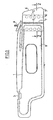
- the sun visor shown in Figs. 1 to 3 comprises a frame 1 of metal wire, a lining material 2 and a coating 3 respectively covering the two faces 3a and 3b of the sun visor.
- the latter conventionally comprises articulation means 4 and latching 5 for blocking it relative to the roof of the vehicle.
- the wire frame is interrupted at a certain distance from the edge 6 of the sun visor closest to the side part of the roof and a fold line 7 is provided extending approximately transversely to the longitudinal direction of the sun visor and separating the latter into a main part 8 and an end part 9.
- a fold line 7 is provided extending approximately transversely to the longitudinal direction of the sun visor and separating the latter into a main part 8 and an end part 9.
- the two covering sheets 3a, 3b are welded to each other, continuously or discontinuous, through the lining material. There is thus produced along the fold line a weakening of the sun visor of the end part 9 can then be folded and oriented so as to match the shape of the roof in this area (Fig. 2).
- a stiffening member is placed inside the lining material which can for example be made of polyamide and which can have the shape shown in the drawing.
- This stiffening member is here constituted by a plate 10 having a thickness of about 0.8 mm and comprising along the fold line of the recesses 11 allowing the assembly by welding between the two sheets of coating 3a, 3b.
- the stiffening member comprises on either side of the recesses 11 a series of orifices 12.
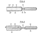
- the invention is applied to a sun visor of the type described in French patent application No. 2491402 published on 9/4/82.
- This sun visor comprises two hollow half-shells, 21, 22 made of a suitable plastic material, for example polypropylene which are joined along a joint plane. These two half-shells are covered with a coating 23 covering the two faces 23a, 23b of the sun visor.
- the two half-shells define along a fold line 24 a zone 25 of reduced thickness in which are also provided orifices 26.
- the two covering sheets 23a, 23b are assembled by welding at the level of these orifices.
- the sun visor has a lining 31 formed by two layers of foam 31, 32 of identical thickness, against which is glued a stiffening member 33, disposed in the area of the line of folding 34.
- the layer 31 extends to the end of the sun visor, while the layer 32 is interrupted at the fold line. On the other side of this line is provided a layer of foam 35 of smaller thickness, which gives the foldable part 36 an equally reduced thickness. In general, this folding part can therefore have a thickness different from that of the main part of the sun visor.
- the invention makes it possible to solve the problem posed. Indeed, the manufacturing process remains very simple and does not require any special tools; the covering is perfectly held in place, even in the concave part of the sun visor, given the bond by welding with the covering sheet arranged on the opposite face of the sun visor; the deformation of the end part of the sun visor is chosen at will by the user since no rigid metal frame is located in the region of the fold line.
- the welding operation along the fold line can be carried out easily at the same time as the usual welding of the covering material and while the sun visor is arranged flat, the curved shape being given only 'later.
- weld line can be continuous or discontinuous and carried out with points of suitable shape, depending on the desired effect.
Description
La présente invention a pour objet un pare-soleil galbé, notamment pour véhicule automobile.The present invention relates to a curved sun visor, in particular for a motor vehicle.
Afin de permettre aux pare-soleil d'épouser la forme du pavillon du véhicule, on a déjà prévu de leur donner une forme galbée au voisinage de leurs extrémités proches de la partie latérale du pavillon. Dans la technique connue, cette conformation particulière implique des opérations longues et onéreuses, à savoir: mise en forme des armatures en fils métalliques, réalisation d'électrodes de soudure galbées pour effectuer la soudure périphérique du matériau de revêtement, difficulté et perte de temps lors de la mise en place des différents composants pour réaliser cette soudure. De plus, pour éviter que le revêtement du pare-soleil ne forme des plis dans la zone concave de la partie galbée, il est nécessaire de réaliser un préformage de ce revêtement ou bien un passage à la chaleur après soudure, ce qui complique encore les opérations de fabrication et augmente les coûts.In order to allow the sun visors to follow the shape of the roof of the vehicle, provision has already been made to give them a curved shape in the vicinity of their ends close to the lateral part of the roof. In the known technique, this particular conformation involves long and costly operations, namely: shaping the reinforcements in metal wires, making curved welding electrodes to perform the peripheral welding of the coating material, difficulty and loss of time during the establishment of the various components to achieve this weld. In addition, to prevent the coating of the sun visor from forming folds in the concave area of the curved part, it is necessary to preform this coating or even heat transfer after welding, which further complicates the manufacturing operations and increases costs.
L'invention concerne donc plus précisément, les pare-soleil du type comprenant une armature, un matériau de revêtement, des moyens d'articulation sur le pavillon du véhicule, et une partie d'extrémité galbée destinée à épouser la forme du pavillon, dans lequel le galbe est obtenu au moyen d'au moins une ligne de pliage divisant le pare-soleil en une partie principale et une partie d'extrémité pouvant être orientée obliquement par rapport à la partie principale, l'armature s'arrêtant au voisinage de la ligne de pliage.The invention therefore relates more precisely, the sun visors of the type comprising a frame, a covering material, means of articulation on the roof of the vehicle, and a curved end portion intended to follow the shape of the roof, in which the curve is obtained by means of at least one fold line dividing the sun visor into a main part and an end part which can be oriented obliquely with respect to the main part, the frame ending in the vicinity of the fold line.
Un tel pare-soleil est décrit dans le document US-A-3 610 680. Cependant, l'extrémité pliable du pare-soleil ainsi réalisée ne présente pas une tenue et un aspect extérieur réellement satisfaisants, la fabrication de ce pare-soleil étant en outre relativement compliquée et onéreuse.Such a sun visor is described in document US-A-3 610 680. However, the foldable end of the sun visor thus produced does not have a truly satisfactory appearance and appearance, the manufacture of this sun visor being furthermore relatively complicated and expensive.
Il est également connu d'assembler par soudure l'une à l'autre le long de la ligne de pliage, au moins en certains emplacements de celle-ci, deux feuilles de revêtement recouvrant les faces opposées du pare-soleil.It is also known to assemble by welding one to the other along the fold line, at least in certain locations thereof, two sheets of covering covering the opposite faces of the sun visor.
L'invention a donc pour but de réaliser un pare-soleil galbé dont la partie pliable présente une meilleure tenue et un aspect extérieur plus satisfaisant, et qui de plus puisse être fabriqué de façon plus simple, plus fiable et moins onéreuse que les pare-soleil antérieurs.The object of the invention is therefore to produce a curved sun visor, the foldable part of which has better hold and a more satisfactory external appearance, and which moreover can be manufactured in a simpler, more reliable and less expensive manner than previous sun.
Conformément à l'invention, le pare-soleil comporte un organe raidisseur disposé dans la zone de la ligne de pliage, et qui présente des évidements le long de la ligne de pliage, les feuilles de revêtement recouvrant les deux faces étant assemblées par soudure l'une à l'autre au niveau desdits évidements.According to the invention, the sun visor comprises a stiffening member disposed in the region of the fold line, and which has recesses along the fold line, the covering sheets covering the two faces being assembled by welding. 'to each other at said recesses.
Cet organe raidisseur, qui peut être par exemple réalisé sous la forme d'une plaquette d'épaisseur convenable, comporte le long de la ligne de pliage des évidements permettant l'assemblage par soudure entre les deux feuilles de revêtement.This stiffening member, which can for example be produced in the form of a plate of suitable thickness, comprises along the fold line of the recesses allowing the assembly by welding between the two sheets of coating.
L'invention sera décrite ci-après plus en détail en se référant aux dessins annexés qui en illustrent plusieurs formes de réalisation non limitatives:
- la Figure 1 est une vue en plan d'un pare-soleil suivant l'invention;
- la Figure 2 est une vue en coupe suivant la ligne II-II de la Figure 1;
- la Figure 3 est une vue en plan d'un organe raidisseur incorporé au pare-soleil;
- les Figures 4 et 5 sont des vues analogues à la Figure 2 représentant deux variantes de réalisation.
- Figure 1 is a plan view of a sun visor according to the invention;
- Figure 2 is a sectional view along line II-II of Figure 1;
- Figure 3 is a plan view of a stiffening member incorporated in the sun visor;
- Figures 4 and 5 are views similar to Figure 2 showing two alternative embodiments.
Le pare-soleil représenté aux Fig. 1 à 3 comporte une armature 1 en fil métallique, un matériau de garnissage 2 et un revêtement 3 recouvrant respectivement les deux faces 3a et 3b du pare-soleil. Ce dernier comporte de façon classique des moyens d'articulation 4 et d'encliquetage 5 permettant de le bloquer par rapport au pavillon du véhicule.The sun visor shown in Figs. 1 to 3 comprises a frame 1 of metal wire, a
L'armature en fil métallique est interrompue à une certaine distance du bord 6 du pare-soleil le plus proche de la partie latérale du pavillon et il est prévu une ligne de pliage 7 s'étendant à peu près transversalement par rapport à la direction longitudinale du pare-soleil et séparant ce dernier en une partie principale 8 et une partie d'extrémité 9. Le long de cette ligne de pliage, les deux feuilles de revêtement 3a, 3b sont soudées l'une sur l'autre, de façon continue ou discontinue, au travers du matériau de garnissage. On réalise ainsi le long de la ligne de pliage un affaiblissement du pare-soleil de la partie d'extrémité 9 peut alors être pliée et orientée de façon à épouser la forme du pavillon dans cette zone (Fig. 2).The wire frame is interrupted at a certain distance from the edge 6 of the sun visor closest to the side part of the roof and a fold line 7 is provided extending approximately transversely to the longitudinal direction of the sun visor and separating the latter into a main part 8 and an
Pour donner à cette extrémité une meilleure tenue, on place à l'intérieur du matériau de garnissage un organe raidisseur qui peut par exemple être réalisé en polyamide et qui peut avoir la forme représentée au dessin. Cet organe raidisseur est ici constitué par une plaquette 10 ayant une épaisseur d'environ 0,8 mm et comportant le long de la ligne de pliage des évidements 11 permettant l'assemblage par soudure entre les deux feuilles de revêtement 3a, 3b. Afin d'améliorer l'ancrage dans le matériau de garnissage, l'organe raidisseur comporte de part et d'autre des évidements 11 une série d'orifices 12.To give this end a better hold, a stiffening member is placed inside the lining material which can for example be made of polyamide and which can have the shape shown in the drawing. This stiffening member is here constituted by a
Dans le mode de réalisation représenté à la Fig. 4, l'invention est appliqué à un pare-soleil du type décrit dans la demande de brevet français No 2491402 publiée le 9/4/82. Ce pare-soleil comporte deux demi-coquilles creuses, 21, 22 réalisées en une matière plastique convenable, par exemple en polypropylène qui sont accolées le long d'un plan de joint. Ces deux demi-coquilles sont recouvertes d'un revêtement 23 recouvrant les deux faces 23a, 23b du pare-soleil. Afin d'obtenir le même résultat que dans le premier mode de réalisation, les deux demi-coquilles délimitent le long d'une ligne de pliage 24 une zone 25 d'épaisseur réduite dans laquelle sont par ailleurs prévus des orifices 26. Les deux feuilles de revêtement 23a, 23b sont assemblées par soudure au niveau de ces orifices.In the embodiment shown in FIG. 4, the invention is applied to a sun visor of the type described in French patent application No. 2491402 published on 9/4/82. This sun visor comprises two hollow half-shells, 21, 22 made of a suitable plastic material, for example polypropylene which are joined along a joint plane. These two half-shells are covered with a
Dans le mode de réalisation de la Fig.5, le pare-soleil comporte un garnissage 31 formé de deux couches de mousse 31, 32 d'épaisseur identique, contre lesquelles est collé un organe raidisseur 33, disposé dans la zone de la ligne de pliage 34.In the embodiment of Fig.5, the sun visor has a
La couche 31 s'étend jusqu'à l'extrémité du pare-soleil, tandis que la couche 32 est interrompue au niveau de la ligne de pliage. De l'autre côté de cette ligne est prévue une couche de mousse 35 d'épaisseur plus faible, ce qui donne à la partie pliable 36 une épaisseur également réduite. D'une façon générale cette partie repliable peut donc avoir une épaisseur différente de celle de la partie principale du pare-soleil.The
Dans les divers modes de réalisation prévus, l'invention permet bien de résoudre le problème posé. En effet, le procédé de fabrication demeure très simple et ne nécessite pas d'outillage particulier; le revêtement est parfaitement maintenu en place, même dans la partie concave du pare-soleil, étant donné la liaison par soudure avec la feuille de revêtement disposée sur la face opposée du pare-soleil; la déformation de la partie d'extrémité du pare-soleil est choisie à volonté par l'utilisateur puisque aucune armature métallique rigide ne se trouve dans la zone de la ligne de pliage.In the various embodiments provided, the invention makes it possible to solve the problem posed. Indeed, the manufacturing process remains very simple and does not require any special tools; the covering is perfectly held in place, even in the concave part of the sun visor, given the bond by welding with the covering sheet arranged on the opposite face of the sun visor; the deformation of the end part of the sun visor is chosen at will by the user since no rigid metal frame is located in the region of the fold line.
De plus, l'opération de soudure le long de la ligne de pliage peut être effectuée aisément en même temps que la soudure habituelle du matériau de revêtement et alors que le pare-soleil est disposé à plat, la forme galbée n'étant donnée qu'ultérieurement.In addition, the welding operation along the fold line can be carried out easily at the same time as the usual welding of the covering material and while the sun visor is arranged flat, the curved shape being given only 'later.
Enfin, on peut noter que la ligne de soudure peut être continue ou discontinue et effectuée avec des points de forme appropriée, suivant l'effet recherché.Finally, it can be noted that the weld line can be continuous or discontinuous and carried out with points of suitable shape, depending on the desired effect.
Claims (4)
Applications Claiming Priority (2)
| Application Number | Priority Date | Filing Date | Title |
|---|---|---|---|
| FR8025052A FR2494641B1 (en) | 1980-11-26 | 1980-11-26 | SUN VISORS, ESPECIALLY FOR MOTOR VEHICLES |
| FR8025052 | 1980-11-26 |
Publications (2)
| Publication Number | Publication Date |
|---|---|
| EP0053053A1 EP0053053A1 (en) | 1982-06-02 |
| EP0053053B1 true EP0053053B1 (en) | 1985-05-22 |
Family
ID=9248355
Family Applications (1)
| Application Number | Title | Priority Date | Filing Date |
|---|---|---|---|
| EP19810401680 Expired EP0053053B1 (en) | 1980-11-26 | 1981-10-23 | Sun visor, especially for vehicles |
Country Status (4)
| Country | Link |
|---|---|
| EP (1) | EP0053053B1 (en) |
| DE (1) | DE3170634D1 (en) |
| ES (1) | ES261457Y (en) |
| FR (1) | FR2494641B1 (en) |
Families Citing this family (3)
| Publication number | Priority date | Publication date | Assignee | Title |
|---|---|---|---|---|
| FR2527994A1 (en) * | 1982-06-04 | 1983-12-09 | Faure Bertrand | IMPROVEMENTS IN SUN VISORS |
| DE19731534C2 (en) * | 1997-07-23 | 2001-03-08 | Johnson Contr Interiors Gmbh | Sun visors for vehicles |
| DE10356191A1 (en) * | 2003-12-02 | 2005-06-30 | Susanne Zimmermann | Sunlight protection device, especially a sunblind for a motor vehicle, has a folding out side flap that is used to protect the user from sunlight entering through the vehicle side window |
Family Cites Families (4)
| Publication number | Priority date | Publication date | Assignee | Title |
|---|---|---|---|---|
| US3199913A (en) * | 1963-06-13 | 1965-08-10 | Gen Motors Corp | Vehicle body sunshade |
| US3343867A (en) * | 1965-06-17 | 1967-09-26 | Gen Motors Corp | Visor means |
| FR2054798A6 (en) * | 1969-07-30 | 1971-05-07 | Talpain Louis Roger | |
| US3610680A (en) * | 1970-04-29 | 1971-10-05 | Gen Motors Corp | Vehicle body sunshade |
-
1980
- 1980-11-26 FR FR8025052A patent/FR2494641B1/en not_active Expired
-
1981
- 1981-10-23 EP EP19810401680 patent/EP0053053B1/en not_active Expired
- 1981-10-23 DE DE8181401680T patent/DE3170634D1/en not_active Expired
- 1981-11-16 ES ES1981261457U patent/ES261457Y/en not_active Expired
Also Published As
| Publication number | Publication date |
|---|---|
| FR2494641B1 (en) | 1985-10-25 |
| ES261457U (en) | 1982-11-01 |
| EP0053053A1 (en) | 1982-06-02 |
| DE3170634D1 (en) | 1985-06-27 |
| ES261457Y (en) | 1983-04-01 |
| FR2494641A1 (en) | 1982-05-28 |
Similar Documents
| Publication | Publication Date | Title |
|---|---|---|
| EP0394123B1 (en) | Rollerblind for vehicle rear window and manufacturing process | |
| EP1378402B2 (en) | Profile for structural element of an automobile and its corresponding chassis | |
| FR2863212A1 (en) | METHOD FOR MANUFACTURING A SEAL, ESPECIALLY A SLIDER FOR GLAZING A MOTOR VEHICLE, AND JOINT SO MANUFACTURED | |
| EP1580098A1 (en) | Vehicle roof, and vehicle with such a roof | |
| EP0053053B1 (en) | Sun visor, especially for vehicles | |
| FR2643306A1 (en) | METHOD FOR MANUFACTURING A COATING FOR A PNEUMATIC SAFETY CUSHION UNIT | |
| EP0156711A1 (en) | Welded double-walled tube and method for its manufacture | |
| FR2591155A1 (en) | Wheel suspension for a transport means | |
| FR2713540A1 (en) | Hidden weld joint for hollow parts | |
| WO2000068526A1 (en) | Ceiling slab | |
| FR2909969A1 (en) | METHOD FOR ASSEMBLING SKIN PARTS | |
| EP0903285A1 (en) | Mudguard flap for motor vehicles | |
| FR2880307A1 (en) | Sliding member for motor vehicle seat adjuster has seat support laser welded to flat upper wall of inverted U-section slider | |
| FR2553905A1 (en) | Detachable visor which can be mounted on a pair of spectacles | |
| FR2903369A3 (en) | Motor vehicle`s roof assembling method, involves folding edge by wheel or die, to define section with wings, and connecting free wing to shoulder by gum layer or welding realized between ends of free wing and one of sheets, respectively | |
| EP3350066B1 (en) | Assembly method between two elements made of sheet metal | |
| EP0746440B1 (en) | Method for making frames for bicycles, motorbikes and similar vehicles, and resulting frames | |
| EP1813512B1 (en) | Windscreen post and method of manufacturing said post | |
| EP3792118B1 (en) | Trim component for a steering column of a motor vehicle | |
| EP0456561B1 (en) | Strengthening core for sections used particularly in the motor industry | |
| FR3075303B1 (en) | SEAL FOR MOTOR VEHICLE COMPRISING AN ADHESIVE MEANS AND AT LEAST ONE FASTENING CLIP | |
| FR2921023A1 (en) | FRAME FOR SEAT BACKREST OF MOTOR VEHICLE | |
| EP1586496B1 (en) | Vehicle roof and vehicle having such a roof | |
| FR3126941A1 (en) | Wiping medium adapter device and windscreen wiper thus equipped and method of making the device | |
| EP2080691B1 (en) | Automobile framework stiffener, framework and method for fixing such a stiffener to a framework |
Legal Events
| Date | Code | Title | Description |
|---|---|---|---|
| PUAI | Public reference made under article 153(3) epc to a published international application that has entered the european phase |
Free format text: ORIGINAL CODE: 0009012 |
|
| AK | Designated contracting states |
Designated state(s): DE GB IT SE |
|
| 17P | Request for examination filed |
Effective date: 19821125 |
|
| ITF | It: translation for a ep patent filed |
Owner name: STUDIO ING. ALFREDO RAIMONDI |
|
| GRAA | (expected) grant |
Free format text: ORIGINAL CODE: 0009210 |
|
| AK | Designated contracting states |
Designated state(s): DE GB IT SE |
|
| REF | Corresponds to: |
Ref document number: 3170634 Country of ref document: DE Date of ref document: 19850627 |
|
| PLBI | Opposition filed |
Free format text: ORIGINAL CODE: 0009260 |
|
| 26 | Opposition filed |
Opponent name: GEBR. HAPPICH GMBH Effective date: 19860207 |
|
| PLBN | Opposition rejected |
Free format text: ORIGINAL CODE: 0009273 |
|
| STAA | Information on the status of an ep patent application or granted ep patent |
Free format text: STATUS: OPPOSITION REJECTED |
|
| 27O | Opposition rejected |
Effective date: 19890227 |
|
| PGFP | Annual fee paid to national office [announced via postgrant information from national office to epo] |
Ref country code: DE Payment date: 19900830 Year of fee payment: 10 |
|
| PGFP | Annual fee paid to national office [announced via postgrant information from national office to epo] |
Ref country code: GB Payment date: 19901015 Year of fee payment: 10 |
|
| PGFP | Annual fee paid to national office [announced via postgrant information from national office to epo] |
Ref country code: SE Payment date: 19901026 Year of fee payment: 10 |
|
| ITTA | It: last paid annual fee | ||
| PG25 | Lapsed in a contracting state [announced via postgrant information from national office to epo] |
Ref country code: GB Effective date: 19911023 |
|
| PG25 | Lapsed in a contracting state [announced via postgrant information from national office to epo] |
Ref country code: SE Effective date: 19911024 |
|
| GBPC | Gb: european patent ceased through non-payment of renewal fee | ||
| PG25 | Lapsed in a contracting state [announced via postgrant information from national office to epo] |
Ref country code: DE Effective date: 19920701 |
|
| EUG | Se: european patent has lapsed |
Ref document number: 81401680.4 Effective date: 19920510 |