EP3350066B1 - Assembly method between two elements made of sheet metal - Google Patents
Assembly method between two elements made of sheet metal Download PDFInfo
- Publication number
- EP3350066B1 EP3350066B1 EP16774527.2A EP16774527A EP3350066B1 EP 3350066 B1 EP3350066 B1 EP 3350066B1 EP 16774527 A EP16774527 A EP 16774527A EP 3350066 B1 EP3350066 B1 EP 3350066B1
- Authority
- EP
- European Patent Office
- Prior art keywords
- edge
- assembly
- free end
- welding
- elements
- Prior art date
- Legal status (The legal status is an assumption and is not a legal conclusion. Google has not performed a legal analysis and makes no representation as to the accuracy of the status listed.)
- Active
Links
- 238000000034 method Methods 0.000 title claims description 38
- 229910052751 metal Inorganic materials 0.000 title claims description 13
- 239000002184 metal Substances 0.000 title description 7
- 238000003466 welding Methods 0.000 claims description 34
- 239000011324 bead Substances 0.000 claims description 30
- 239000000853 adhesive Substances 0.000 claims description 21
- 230000001070 adhesive effect Effects 0.000 claims description 21
- 238000010891 electric arc Methods 0.000 claims description 7
- 239000011261 inert gas Substances 0.000 claims description 4
- 238000005493 welding type Methods 0.000 claims description 4
- 239000000565 sealant Substances 0.000 claims description 3
- WFKWXMTUELFFGS-UHFFFAOYSA-N tungsten Chemical compound [W] WFKWXMTUELFFGS-UHFFFAOYSA-N 0.000 claims description 3
- 229910052721 tungsten Inorganic materials 0.000 claims description 3
- 239000010937 tungsten Substances 0.000 claims description 3
- 238000000151 deposition Methods 0.000 claims description 2
- 239000004800 polyvinyl chloride Substances 0.000 claims 1
- 239000003292 glue Substances 0.000 description 37
- 238000005219 brazing Methods 0.000 description 11
- 238000004513 sizing Methods 0.000 description 9
- 238000001962 electrophoresis Methods 0.000 description 8
- 229910000679 solder Inorganic materials 0.000 description 4
- 238000005476 soldering Methods 0.000 description 4
- 238000004519 manufacturing process Methods 0.000 description 3
- 229910000831 Steel Inorganic materials 0.000 description 2
- 238000004026 adhesive bonding Methods 0.000 description 2
- XAGFODPZIPBFFR-UHFFFAOYSA-N aluminium Chemical compound [Al] XAGFODPZIPBFFR-UHFFFAOYSA-N 0.000 description 2
- 239000003517 fume Substances 0.000 description 2
- 238000009499 grossing Methods 0.000 description 2
- 238000009434 installation Methods 0.000 description 2
- 238000002844 melting Methods 0.000 description 2
- 230000008018 melting Effects 0.000 description 2
- 238000006116 polymerization reaction Methods 0.000 description 2
- 230000001737 promoting effect Effects 0.000 description 2
- 239000010959 steel Substances 0.000 description 2
- RYGMFSIKBFXOCR-UHFFFAOYSA-N Copper Chemical compound [Cu] RYGMFSIKBFXOCR-UHFFFAOYSA-N 0.000 description 1
- 229910052782 aluminium Inorganic materials 0.000 description 1
- 230000000712 assembly Effects 0.000 description 1
- 238000000429 assembly Methods 0.000 description 1
- 229910052802 copper Inorganic materials 0.000 description 1
- 239000010949 copper Substances 0.000 description 1
- 230000006378 damage Effects 0.000 description 1
- 230000006866 deterioration Effects 0.000 description 1
- 230000008034 disappearance Effects 0.000 description 1
- 238000009826 distribution Methods 0.000 description 1
- 230000000694 effects Effects 0.000 description 1
- 229920006335 epoxy glue Polymers 0.000 description 1
- 239000000835 fiber Substances 0.000 description 1
- 239000000945 filler Substances 0.000 description 1
- 239000007789 gas Substances 0.000 description 1
- 238000010438 heat treatment Methods 0.000 description 1
- 238000012423 maintenance Methods 0.000 description 1
- 230000004048 modification Effects 0.000 description 1
- 238000012986 modification Methods 0.000 description 1
- 238000003032 molecular docking Methods 0.000 description 1
- 230000007935 neutral effect Effects 0.000 description 1
- 239000004814 polyurethane Substances 0.000 description 1
- 229920002635 polyurethane Polymers 0.000 description 1
- 238000007789 sealing Methods 0.000 description 1
Images


Classifications
-
- B—PERFORMING OPERATIONS; TRANSPORTING
- B62—LAND VEHICLES FOR TRAVELLING OTHERWISE THAN ON RAILS
- B62D—MOTOR VEHICLES; TRAILERS
- B62D65/00—Designing, manufacturing, e.g. assembling, facilitating disassembly, or structurally modifying motor vehicles or trailers, not otherwise provided for
- B62D65/02—Joining sub-units or components to, or positioning sub-units or components with respect to, body shell or other sub-units or components
-
- B—PERFORMING OPERATIONS; TRANSPORTING
- B62—LAND VEHICLES FOR TRAVELLING OTHERWISE THAN ON RAILS
- B62D—MOTOR VEHICLES; TRAILERS
- B62D25/00—Superstructure or monocoque structure sub-units; Parts or details thereof not otherwise provided for
- B62D25/06—Fixed roofs
-
- B—PERFORMING OPERATIONS; TRANSPORTING
- B62—LAND VEHICLES FOR TRAVELLING OTHERWISE THAN ON RAILS
- B62D—MOTOR VEHICLES; TRAILERS
- B62D27/00—Connections between superstructure or understructure sub-units
- B62D27/02—Connections between superstructure or understructure sub-units rigid
- B62D27/026—Connections by glue bonding
Definitions
- the present invention relates to a method of assembly between two sheet metal elements and, more particularly, for the assembly of two motor vehicle parts such as a roof and a body of a motor vehicle.
- a braze-soldering assembly allows a continuous junction of the parts to be assembled, the disappearance of the junction groove, and therefore the trim strip. This has many aesthetic and mechanical benefits.
- solder bead In order to meet the aesthetic and mechanical criteria, the solder bead must be as free as possible from irregularities and waterproof, that is to say free of holes.
- Such a method is generally implemented in a robotic manner.
- a head of a robotic arm is able to move along a braze line between a roof of a motor vehicle and a side of a passenger compartment of said vehicle.
- the device comprises a means for distributing a filler metal to a brazing zone located on the solder line, said distribution means being associated with a melting means capable of allowing the solder to be melted. at the level of said brazing zone.
- a melting means may be a laser head capable of emitting a laser beam towards the area to be soldered.
- the pavilion arrives in the laser cabin pointed at its front and rear sleepers. This ensures the docking between the parts at the beginning and end of the cord. It also makes the geometry on each side independent by creating a neutral fiber in the middle of the roof. In this way, one can weld the two sides of the pavilion separately one after the other.
- the present invention proposes a method of assembly between two parts such as a horn and a body side that can be used on parts that could also be assembled in particular by a laser brazing or equivalent method. implemented robotically.
- the assembly zone is preferably band-shaped along the first element.
- Such an adhesive may be of the single-component type and polymerizable in the cataphoresis bath. It can also be of the two-component type and polymerizable at room temperature.
- the adhesive is deposited in a discontinuous line, the sizing line having a succession of dashes of glue deposited and sections free of glue, the weld can then be arranged discontinuously it also at sections of the assembly area free of glue.
- the at least one weld made may consist of a continuous weld seam, a succession of weld points or a succession of weld seams.
- a point or weld bead corresponding to each section of the adhesive-free sizing line. It is also possible to make a point or weld seam of in a regular way but of different frequency, for example one can predict to achieve this point of welding that every two dashes of glue namely a dash of glue a space without glue, a glue dash a space without glue with a weld point , then a dash of glue, a space without glue, a dash of glue, then a space without glue with point of welding.
- the sizing line and the weld line are therefore parallel, but spaced from each other at the assembly zone, preferably each along an edge of said zone.
- the elements to be assembled sheet metal are for example, two steel elements, a steel element and the second aluminum element.
- the first element is assembled on the second element forming an assembly zone, delimited by the free end of the edge of the first element, while, opposite the free end. of the edge of the first element, the two elements extend beyond this assembly zone by moving away from each other and forming between them a groove, preferably substantially V and forming the other edge of the assembly zone, in which can be made at least one weld bead, which can be continuous or discontinuous, thus also defining the assembly area.
- the first element may have a dropped edge intended to abut against the second element, the assembly zone thus forms an assembly strip delimited by the free end of the dropped edge and the fold forming this edge. fallen, at least one weld bead being formed at the junction between the first element and the second element at the bend of the first element.
- the first element has a curved edge, the curved portion of which abuts against the second element forms a groove junction with said second element while the free end of the curved edge is intended to extend, substantially beyond the junction, along the second element, forming the assembly zone, at least one weld bead being formed in the groove formed between the first element and the second element.
- each longitudinal edge has a curved edge and the second element is a body side.
- a sealing bead such as a glue joint of the PVC or putty type which, by smoothing, makes it possible to guarantee both the aesthetic appearance and the tightness of the assembly zone, in particular in the case of bonding and / or batch welding.
- the welding method used in the method of the invention is an electric arc welding such as an electric arc welding with a non-fuse electrode of the TIG (Tungsten Inert Gas) welding type, a welding to the electric arc with a gaseous fuse electrode wire of the MIG-MAG (Metal Inert Gas - Metal Active Gas) welding type such as a copper base wire (CuSi3% type), for an assembly with an aluminum flag, wire type AlSi3Mn1.
- TIG Transmission Inert Gas
- MIG-MAG Metal Inert Gas - Metal Active Gas
- Such an assembly method is particularly suitable for allowing the assembly of a roof liner on a vehicle body.
- the first metal element is therefore a flag and the second metal element is a body side.
- the assembly thus produced is particularly simple to implement and can therefore easily subnitute a roof horn assembly on a vehicle body by laser welding. It can in particular be performed manually by technicians without the need for a robotic station.
- a roof pavilion therefore has two curved longitudinal edges whose curved portion rests against the upper part of a body side forming with said body side a throat junction whose cross section substantially represents a V.
- the end Free of the curved edge extends beyond this junction along the body side.
- a bead of structural glue can be deposited discontinuously along the body side, then the flag is deposited on the body side, the end of the curved edge having an inclination such as the curved edge.
- the flag crushes the bead of discontinuous glue deposited on the body side generating a discontinuous connection between the flag and the body side by gluing.
- the flag is welded to the body side using, for example, a method of electric arc welding, for example by TIG, by producing a discontinuous weld bead, each portion of the weld seam or welding point, being deposited in the junction groove, in a portion of said junction free of glue.
- the invention therefore also relates to a vehicle in which the roof flag is assembled on a vehicle body according to the method of the invention.
- the first element is assembled on the second element forming an assembly zone, one edge of which is at least the free end of the edge of the first element and the two elements.
- elements extending beyond the assembly strip being in abutment with one another, the opposite edge of the assembly zone being delimited by welding points formed through the two superposed elements, " by transparency ", for example by electrical resistance or laser welding spots.
- the sizing line is preferably discontinuous and the spot welds are preferably made at locations corresponding to sections of the assembly area free of glue.
- the invention also relates to an assembly between two sheet metal elements, the edge of the first element being shaped to bear against the second element, forming an assembly zone delimited at least by the free end of the edge of the first element, whereas, on the side of the assembly zone opposite the free end of the edge of the first element, the first and second elements both extend beyond this assembly zone, characterized in that the edge of the first element is assembled on the second element by at least one bead of adhesive extending, at the assembly area, along the free end of the edge of the first element, and at least one weld between the two elements along the edge of the assembly zone, opposite the edge of the assembly zone constituted by the free end of the edge of the first element.
- Such an assembly can advantageously be obtained with the method of the invention.
- a roof horn 1 is assembled on a vehicle body 2 by means of a laser braze-welding.
- Such roof lodge 1 has curved longitudinal edges 11 which are housed against the upper portion 21 of a body side.
- the curved portion 12 of the edge 11 of the flag 1 forms against the body side 21 a throat-shaped junction 3 whose cross-sectional profile is substantially V-shaped.
- the free end 13 of the edge 11 extends beyond the junction with the body side 21 and extends substantially parallel thereto, under the groove 3 thus formed in the frame of reference 2.
- the assembly is then performed by laser brazing by depositing a weld bead 4 in the groove 3.
- the method according to the invention makes it possible to propose on a flag 1 and a body side 21 similar, an assembly process which can be replace the braze-welding laser without the need to change the elements to be assembled.
- a bead of glue 5 is deposited along the body side 21 along a discontinuous sizing line, thus providing a succession of dashes of glue along the body side 21 and of glue-free side sections of the body. .
- This adhesive bead 5 is further deposited along the body side 21 so that when the flag 1 is deposited on it (cf. figure 2b ), this adhesive bead 5 is crushed between the body side 21 and the free end 13 of the curved edge 11, substantially below the groove 3 formed at the junction between the roof 1 and the body side 21 as can be seen on the figure 3b .
- the assembly zone is thus defined between the free end 13 of the curved edge 11 and the junction with the body side 21.
- the bead of structural adhesive deposited is discontinuous to leave areas where in the next phase the glue will not be present under the TIG welding bead to prevent its destruction
- the structural adhesive is functional after its polymerization, the latter intervening only after the heat treatment consisting of the passage of the body in cataphoresis, for example.
- weld points 6 consist of weld seams obtained by means of an electric arc welding such as with a non-fusible electrode of TIG (Tungsten Inert Gas) welding type.
- TIG welding beads 6 for example are deposited in the bottom of the groove 3 at the junction of the horn 1 and the body side 21 on the sections of this junction corresponding to the zones without glue of the discontinuous sizing line. In this way, it avoids all risks of fumes related to the burning of the glue and it also avoids the deterioration of the bonding.
- TIG cords of 10 to 15 mm are preferably made along the pavilion in order to maintain it. Thus the geometry of the pavilion is frozen.
- the body is cataphoresed.
- the glue under the effect of the temperature in cataphoresis polymerizes.
- a seal 7 such as a PVC type adhesive, is deposited in the groove 3 all along the latter. or sealant which ensures both the tightness of the assembly and the appearance of the joint by smoothing, see Figures 2d and 3d .
- the glue 7 is smoothed to obtain a connection fillet between the roof and the body side.
- a method according to the invention allows a very economical solution of assembly of these elements. This solution is manual and easy to implement and avoids the use of other more expensive assembly methods such as laser brazing, some sites are not equipped.
Description
La présente invention se rapporte à un procédé d'assemblage entre deux éléments en tôle métallique et, plus particulièrement, destiné à l'assemblage de deux pièces de véhicule automobile tel qu'un pavillon et une caisse d'un véhicule automobile.The present invention relates to a method of assembly between two sheet metal elements and, more particularly, for the assembly of two motor vehicle parts such as a roof and a body of a motor vehicle.
Dans certains domaines techniques, comme le domaine automobile par exemple, on a proposé de réaliser l'assemblage de deux éléments en tôle métallique par brasage, ce qui permet d'éviter de nombreux inconvénients d'un assemblage traditionnel par soudure électrique, notamment le fait qu'un tel mode d'assemblage nécessite la réalisation de points de soudure électriques (abrégés en PSE) au fond d'une gorge de jonction entre les deux pièces à assembler, ladite gorge étant masquée par une bande enjoliveur.In certain technical fields, such as the automotive field for example, it has been proposed to assemble two sheet metal elements by brazing, which avoids many disadvantages of a traditional assembly by electric welding, including the fact that such a method of assembly requires the realization of electrical soldering points (abbreviated PSE) at the bottom of a junction groove between the two parts to be assembled, said groove being masked by a trim strip.
Un assemblage par soudo-brasage permet une jonction continue des pièces à assembler, la disparition de la gorge de jonction, et donc de la bande enjoliveur. Il s'ensuit de nombreux avantages esthétiques et mécaniques.A braze-soldering assembly allows a continuous junction of the parts to be assembled, the disappearance of the junction groove, and therefore the trim strip. This has many aesthetic and mechanical benefits.
Afin de répondre aux critères esthétiques et mécaniques, le cordon de brasage doit être le plus possible exempt d'irrégularités et étanche, c'est-à-dire exempt de trou.In order to meet the aesthetic and mechanical criteria, the solder bead must be as free as possible from irregularities and waterproof, that is to say free of holes.
On a ainsi proposé de réaliser un soudo-brasage au laser d'un pavillon d'un véhicule automobile et d'un côté d'un habitacle dudit véhicule automobile tel que décrit dans
Un tel procédé est généralement mis en oeuvre de manière robotisée. Ainsi, une tête d'un bras robotisé est apte à se déplacer le long d'une ligne de brasure entre un pavillon d'un véhicule automobile et un côté d'un habitacle dudit véhicule. Le dispositif comprend un moyen de distribution d'un métal d'apport à destination d'une zone à braser située sur la ligne de brasure, ledit moyen de distribution étant associé à un moyen de fusion apte à permettre la fusion du métal d'apport au niveau de ladite zone à braser. Un moyen de fusion peut être une tête laser apte à émettre un faisceau laser en direction de la zone à braser. Ainsi, une opération d'installation d'un pavillon sur un habitacle se déroule de la façon suivante. Tout d'abord un robot vient mettre en place le pavillon sur l'habitacle. L'ensemble est ensuite amené dans la cabine laser pour l'opération de brasage. Le pavillon arrive dans la cabine laser pointé sur ses traverses avant et arrière. Cela permet de garantir l'accostage entre les pièces au début et fin du cordon. Cela permet également de rendre indépendant la géométrie de chaque côté en créant une fibre neutre au milieu du pavillon. De cette façon, on peut soudobraser les deux côtés du pavillon de façon séparée l'un après l'autre.Such a method is generally implemented in a robotic manner. Thus, a head of a robotic arm is able to move along a braze line between a roof of a motor vehicle and a side of a passenger compartment of said vehicle. The device comprises a means for distributing a filler metal to a brazing zone located on the solder line, said distribution means being associated with a melting means capable of allowing the solder to be melted. at the level of said brazing zone. A melting means may be a laser head capable of emitting a laser beam towards the area to be soldered. Thus, a flag installation operation on a passenger compartment takes place as follows. First a robot comes to set up the flag on the cockpit. The assembly is then brought into the laser cabin for the soldering operation. The pavilion arrives in the laser cabin pointed at its front and rear sleepers. This ensures the docking between the parts at the beginning and end of the cord. It also makes the geometry on each side independent by creating a neutral fiber in the middle of the roof. In this way, one can weld the two sides of the pavilion separately one after the other.
Cependant, dans certaines installations de production, il n'est pas toujours possible de mettre en oeuvre de tels assemblages robotisés. Aussi, pour réaliser des véhicules similaires, on doit mettre en oeuvre des procédés d'assemblage différents nécessitant de modifier le pavillon et/ou le côté de caisse. On aboutit alors à une diversité dans la conception des pièces destinées pourtant à constituer des véhicules identiques à la base ce qui génère des coûts.However, in some production facilities, it is not always possible to implement such robotic assemblies. Also, to make similar vehicles, one must implement different assembly processes requiring modification of the flag and / or the body side. This leads to a diversity in the design of the parts intended yet to constitute identical vehicles at the base which generates costs.
Afin de pallier ces inconvénients, la présente invention propose un procédé d'assemblage entre deux pièces tel qu'un pavillon et un côté de caisse qui puisse être utilisé sur des pièces qui pourraient également être assemblées notamment par un procédé de soudobrasage au laser ou équivalent mis en oeuvre de manière robotisé.In order to overcome these drawbacks, the present invention proposes a method of assembly between two parts such as a horn and a body side that can be used on parts that could also be assembled in particular by a laser brazing or equivalent method. implemented robotically.
A cet effet, l'invention a pour objet un procédé d'assemblage entre deux éléments en tôle métallique, le bord du premier élément étant conformé pour venir en appui contre le second élément, formant une zone d'assemblage délimitée au moins par l'extrémité libre du bord du premier élément, tandis que, du côté de la zone d'assemblage opposé à l'extrémité libre dudit bord du premier élément, les premier et second éléments s'étendent tous deux au-delà de cette zone d'assemblage, caractérisé en ce que ledit procédé comprend :
- la dépose d'un cordon de colle sur l'un des éléments, de sorte que, lors de l'assemblage des deux éléments, la ligne d'encollage se positionne entre les deux éléments, au niveau de la zone d'assemblage, de préférence le long de l'extrémité libre du bord du premier élément, puis
- la réalisation d'au moins une soudure entre les deux éléments le long du bord de la zone d'assemblage, opposé au bord de la zone d'assemblage constitué par l'extrémité libre du bord du premier élément, cette fixation par soudure permettant de maintenir les deux éléments immobiles l'un par rapport à l'autre jusqu'à une étape de durcissement de la colle finalisant l'assemblage.
- the removal of a bead of glue on one of the elements, so that, during the assembly of the two elements, the sizing line is positioned between the two elements, at the level of the assembly zone, preferably along the free end of the edge of the first element and then
- the realization of at least one weld between the two elements along the edge of the assembly zone, opposite the edge of the assembly zone constituted by the free end of the edge of the first element, this fixing by welding allowing hold the two elements still one relative to the other until a step of hardening the glue finalizing the assembly.
Un tel procédé permet d'obtenir un assemblage par soudo-collage dont la résistance mécanique est particulièrement renforcée, le collage étant un collage dit structural, la soudure ou les points de soudure réalisés le long de la zone d'assemblage mais à l'opposé de la ligne d'encollage par rapport à la zone d'assemblage favorisant cette résistance. De manière avantageuse, la zone d'assemblage est, de préférence, en forme de bande, le long du premier élément.Such a method makes it possible to obtain an assembly by welding-bonding, the mechanical strength of which is particularly enhanced, the bonding being a so-called structural bonding, the welding or the welding points made along the assembly zone but the opposite. of the sizing line with respect to the assembly zone promoting this resistance. Advantageously, the assembly zone is preferably band-shaped along the first element.
On utilise de préférence une colle dite structurale ou de structure telle que du type colle époxy ou polyuréthane, utilisée dans l'industrie automobile. Une telle colle peut être du type mono-composant et polymérisable dans le bain de cataphorèse. Elle peut également être du type bi-composant et polymérisable à température ambiante.It is preferable to use a so-called structural or structural glue such as epoxy glue or polyurethane glue used in the automobile industry. Such an adhesive may be of the single-component type and polymerizable in the cataphoresis bath. It can also be of the two-component type and polymerizable at room temperature.
Selon un mode de mise en oeuvre préféré de l'invention on dépose la colle selon une ligne discontinue, la ligne d'encollage présentant une succession de tirets de colle déposés et des tronçons exempts de colle, la soudure pouvant alors être ménagée de manière discontinue elle aussi au niveau de tronçons de la zone d'assemblage exempts de colle.According to a preferred embodiment of the invention, the adhesive is deposited in a discontinuous line, the sizing line having a succession of dashes of glue deposited and sections free of glue, the weld can then be arranged discontinuously it also at sections of the assembly area free of glue.
On peut ainsi réaliser un encollage dit par dépose de tirets de colle et une soudure de manière discontinue favorisant la tenue de l'assemblage à des emplacements qui ne présentent pas de colle, ce qui, de ce fait, ne génère pas d'émanations liées à la brûlure de la colle et contribue cependant au maintien, immobiles l'un par rapport à l'autre, des deux éléments à assembler jusqu'au durcissement de la colle, par exemple dans le cas d'éléments de caisse de véhicules par passage des éléments assemblés en cataphorèse et favorise la résistance mécanique de l'assemblage. On a donc ainsi une zone d'assemblage présentant le long d'un de ces bords des tirets de colle et sur le bord opposé de la zone, des points ou cordons de soudure ménagés au niveau de tronçons sans colle.It is thus possible to achieve a so-called adhesive bonding glue dye and solder discontinuously promoting the holding of the assembly at locations that do not present glue, which, as a result, does not generate fumes related to the burning of the glue and nevertheless contributes to the maintenance, immobile with respect to one another, of the two elements to be assembled until hardening of the glue, for example in the case of vehicle body elements per passage elements assembled in cataphoresis and promotes the mechanical strength of the assembly. Thus, there is thus an assembly zone having, along one of these edges of the dashes of glue and on the opposite edge of the zone, points or weld seams formed at the level of sections without glue.
Ainsi, la au moins une soudure réalisée peut être constituée d'un cordon de soudure continu, d'une succession de points de soudure ou d'une succession de cordons de soudure.Thus, the at least one weld made may consist of a continuous weld seam, a succession of weld points or a succession of weld seams.
De manière avantageuse, on peut réaliser un point ou cordon de soudure correspondant à chaque tronçon de la ligne d'encollage exempt de colle. On peut également prévoir de réaliser un point ou cordon de soudure de manière régulière mais de fréquence différente, par exemple on peut prévoir de ne réaliser ce point de soudure que tous les deux tirets de colle à savoir un tiret de colle un espace sans colle, un tiret de colle un espace sans colle avec un point de soudure, puis un tiret de colle, un espace sans colle, un tiret de colle, puis un espace sans colle avec point de soudure.Advantageously, it is possible to produce a point or weld bead corresponding to each section of the adhesive-free sizing line. It is also possible to make a point or weld seam of in a regular way but of different frequency, for example one can predict to achieve this point of welding that every two dashes of glue namely a dash of glue a space without glue, a glue dash a space without glue with a weld point , then a dash of glue, a space without glue, a dash of glue, then a space without glue with point of welding.
La ligne d'encollage et la ligne de soudure sont donc parallèles, mais écartées l'une de l'autre au niveau de la zone d'assemblage, préférentiellement chacune le long d'un bord de ladite zone.The sizing line and the weld line are therefore parallel, but spaced from each other at the assembly zone, preferably each along an edge of said zone.
Les éléments à assembler en tôle métallique sont par exemple, deux éléments en acier, un élément en acier et le second élément en aluminium.The elements to be assembled sheet metal are for example, two steel elements, a steel element and the second aluminum element.
Selon un mode de mise en oeuvre préféré, le premier élément est assemblé sur le second élément en formant une zone d'assemblage, délimitée par l'extrémité libre du bord du premier élément, tandis que, à l'opposé de l'extrémité libre du bord du premier élément, les deux éléments s'étendent au-delà de cette zone d'assemblage en s'écartant l'un de l'autre et en formant entre eux une gorge, de préférence sensiblement en V et formant l'autre bord de la zone d'assemblage, dans laquelle peut être réalisé au moins un cordon de soudure, qui peut être continu ou discontinu, délimitant ainsi également la zone d'assemblage.According to a preferred embodiment, the first element is assembled on the second element forming an assembly zone, delimited by the free end of the edge of the first element, while, opposite the free end. of the edge of the first element, the two elements extend beyond this assembly zone by moving away from each other and forming between them a groove, preferably substantially V and forming the other edge of the assembly zone, in which can be made at least one weld bead, which can be continuous or discontinuous, thus also defining the assembly area.
Ainsi, par exemple, le premier élément peut présenter un bord tombé destiné à venir en appui contre le second élément, la zone d'assemblage forme ainsi une bande d'assemblage délimitée par l'extrémité libre du bord tombé et la pliure formant ce bord tombé, au moins un cordon de soudure étant ménagé à la jonction entre le premier élément et le second élément au niveau de la pliure du premier élément.Thus, for example, the first element may have a dropped edge intended to abut against the second element, the assembly zone thus forms an assembly strip delimited by the free end of the dropped edge and the fold forming this edge. fallen, at least one weld bead being formed at the junction between the first element and the second element at the bend of the first element.
Selon un autre exemple de ce mode de réalisation préféré, le premier élément présente un bord recourbé dont la partie courbe amenée en butée contre le second élément forme une jonction en forme de gorge avec ledit second élément tandis que l'extrémité libre du bord recourbé est destinée à s'étendre, sensiblement au-delà de la jonction, le long du second élément, formant la zone d'assemblage, au moins un cordon de soudure étant ménagé dans la gorge formée entre le premier élément et le second élément.According to another example of this preferred embodiment, the first element has a curved edge, the curved portion of which abuts against the second element forms a groove junction with said second element while the free end of the curved edge is intended to extend, substantially beyond the junction, along the second element, forming the assembly zone, at least one weld bead being formed in the groove formed between the first element and the second element.
Ce mode de réalisation est particulièrement avantageux, lorsque le premier élément est un pavillon de toit dont chaque bord longitudinal présente un bord recourbé et le second élément est un côté de caisse.This embodiment is particularly advantageous when the first element is a roof lining, each longitudinal edge has a curved edge and the second element is a body side.
Selon une forme de réalisation préférée de ce mode de réalisation, de manière à garantir l'aspect esthétique de l'assemblage ainsi réalisé, on dépose en outre dans la gorge pourvue d'au moins un cordon de soudure, tout au long de celle-ci, un cordon d'étanchéité tel qu'un joint de colle du type PVC ou mastic qui, par lissage, permet de garantir à la fois l'aspect esthétique et l'étanchéité de la zone d'assemblage, en particulier en cas de collage et/ou soudage discontinu.According to a preferred embodiment of this embodiment, so as to ensure the aesthetic appearance of the assembly thus produced, it is further deposited in the groove provided with at least one weld bead, throughout the ci, a sealing bead such as a glue joint of the PVC or putty type which, by smoothing, makes it possible to guarantee both the aesthetic appearance and the tightness of the assembly zone, in particular in the case of bonding and / or batch welding.
De préférence, le procédé de soudage utilisé dans le procédé de l'invention est un soudage à l'arc électrique tel qu'un soudage à l'arc électrique avec une électrode non fusible du type soudage TIG (Tungsten Inert Gas), un soudage à l'arc électrique avec un fil électrode fusible sous atmosphère gazeuse du type soudage MIG-MAG (Metal Inert Gas - Metal Active Gas) tel qu'un fil base cuivre (type CuSi3%), pour un assemblage avec un pavillon aluminium, fil type AlSi3Mn1.Preferably, the welding method used in the method of the invention is an electric arc welding such as an electric arc welding with a non-fuse electrode of the TIG (Tungsten Inert Gas) welding type, a welding to the electric arc with a gaseous fuse electrode wire of the MIG-MAG (Metal Inert Gas - Metal Active Gas) welding type such as a copper base wire (CuSi3% type), for an assembly with an aluminum flag, wire type AlSi3Mn1.
Un tel procédé d'assemblage est particulièrement approprié pour permettre l'assemblage d'un pavillon de toit sur une caisse de véhicule. Le premier élément métallique est donc un pavillon et le second élément métallique est un côté de caisse. De manière avantageuse, l'assemblage ainsi réalisé est particulièrement simple à mettre en oeuvre et peut donc aisément se subnstituer à un assemblage de pavillon de toit sur caisse de véhicule par soudobrasure au laser. Il peut notamment être réalisé manuellement par des techniciens sans nécessité d'un poste robotisé.Such an assembly method is particularly suitable for allowing the assembly of a roof liner on a vehicle body. The first metal element is therefore a flag and the second metal element is a body side. Advantageously, the assembly thus produced is particularly simple to implement and can therefore easily subnitute a roof horn assembly on a vehicle body by laser welding. It can in particular be performed manually by technicians without the need for a robotic station.
Un pavillon de toit présente donc deux bords longitudinaux recourbés dont la partie courbe vient reposer contre la partie supérieure d'un côté de caisse formant avec ledit côté de caisse une jonction en forme de gorge dont la section transversale représente sensiblement un V. L'extrémité libre du bord recourbé s'étend au-delà de cette jonction le long du côté de caisse. Ainsi, de manière avantageuse, on peut déposer de manière discontinue un cordon de colle de structure le long du côté de caisse, puis on dépose le pavillon sur le côté de caisse, l'extrémité du bord recourbé présentant une inclinaison telle que le bord recourbé du pavillon écrase le cordon de colle discontinu déposé sur le côté de caisse générant une liaison discontinue entre le pavillon et le côté de caisse par collage. Puis, on soude le pavillon au côté de caisse à l'aide, par exemple, d'un procédé de soudage à l'arc électrique, par exemple par TIG, en réalisant un cordon de soudure discontinu, chaque portion du cordon de soudure ou point de soudure, étant déposé dans la gorge de jonction, dans un tronçon de ladite jonction exempt de colle. Une fois le pavillon ainsi assemblé sur la caisse, on met en oeuvre la polymérisation de la colle, en amenant la caisse à l'étape de cataphorèse. Une fois celle-ci réalisée, un joint d'étanchéité est déposé et lissé dans la gorge entre le pavillon et le côté de caisse pour garantir à la fois l'étanchéité et l'aspect esthétique de l'assemblage.A roof pavilion therefore has two curved longitudinal edges whose curved portion rests against the upper part of a body side forming with said body side a throat junction whose cross section substantially represents a V. The end Free of the curved edge extends beyond this junction along the body side. Thus, advantageously, a bead of structural glue can be deposited discontinuously along the body side, then the flag is deposited on the body side, the end of the curved edge having an inclination such as the curved edge. The flag crushes the bead of discontinuous glue deposited on the body side generating a discontinuous connection between the flag and the body side by gluing. Then, the flag is welded to the body side using, for example, a method of electric arc welding, for example by TIG, by producing a discontinuous weld bead, each portion of the weld seam or welding point, being deposited in the junction groove, in a portion of said junction free of glue. Once the flag thus assembled on the body, it implements the polymerization of the glue, bringing the body to the cataphoresis step. Once this is achieved, a seal is deposited and smoothed in the groove between the roof and the body side to ensure both the seal and the aesthetic appearance of the assembly.
Il est ainsi possible d'utiliser le procédé d'assemblage selon l'invention pour assembler un pavillon à une caisse de véhicule à la place d'un procédé d'assemblage par soudobrasage au laser tout en conservant les pièces à assembler identiques. On peut ainsi garantir la production de véhicules identiques sur des sites ayant des installations différentes, certains pouvant être équipés pour réaliser du soudobrasage au laser tandis que d'autres ne présentant pas d'équipements pour un tel soudobrasage au laser peuvent néanmoins fabriquer des véhicules identiques à l'aide du procédé de l'invention et avec les mêmes pièces.It is thus possible to use the assembly method according to the invention for assembling a roof to a vehicle body instead of a method of assembly by laser brazing while retaining identical parts to assemble. It is thus possible to guarantee the production of identical vehicles on sites with different installations, some of which may be equipped to carry out laser brazing, while others without equipment for such a laser brazing may nevertheless manufacture identical vehicles. using the method of the invention and with the same parts.
L'invention a donc pour objet également un véhicule dans lequel le pavillon de toit est assemblé sur une caisse de véhicule selon le procédé de l'invention.The invention therefore also relates to a vehicle in which the roof flag is assembled on a vehicle body according to the method of the invention.
Selon un autre mode de mise en oeuvre du procédé de l'invention, le premier élément est assemblé sur le second élément en formant une zone d'assemblage, dont un bord est au moins l'extrémité libre du bord du premier élément et les deux éléments s'étendant au-delà de la bande d'assemblage en étant en appui l'un sur l'autre, le bord opposé de la zone d'assemblage étant délimité par des points de soudure ménagés au travers des deux éléments superposés, « par transparence », par exemple par des points de soudure par résistance électrique ou par laser.According to another embodiment of the method of the invention, the first element is assembled on the second element forming an assembly zone, one edge of which is at least the free end of the edge of the first element and the two elements. elements extending beyond the assembly strip being in abutment with one another, the opposite edge of the assembly zone being delimited by welding points formed through the two superposed elements, " by transparency ", for example by electrical resistance or laser welding spots.
La ligne d'encollage est de préférence discontinue et les soudures par points sont de préférence réalisées à des emplacements correspondants à des tronçons de la zone d'assemblage exempts de colle.The sizing line is preferably discontinuous and the spot welds are preferably made at locations corresponding to sections of the assembly area free of glue.
L'invention concerne également un assemblage entre deux éléments en tôle métallique, le bord du premier élément étant conformé pour venir en appui contre le second élément, formant une zone d'assemblage délimitée au moins par l'extrémité libre du bord du premier élément, tandis que, du côté de la zone d'assemblage opposé à l'extrémité libre du bord du premier élément, les premier et second éléments s'étendent tous deux au-delà de cette zone d'assemblage, caractérisé en ce que le bord du premier élément est assemblé sur le second élément par au moins un cordon de colle s'étendant, au niveau de la zone d'assemblage, le long de l'extrémité libre du bord du premier élément, et au moins une soudure entre les deux éléments le long du bord de la zone d'assemblage, à l'opposé du bord de la zone d'assemblage constitué par l'extrémité libre du bord du premier élément. Un tel assemblage peut avantageusement être obtenu avec le procédé de l'invention.The invention also relates to an assembly between two sheet metal elements, the edge of the first element being shaped to bear against the second element, forming an assembly zone delimited at least by the free end of the edge of the first element, whereas, on the side of the assembly zone opposite the free end of the edge of the first element, the first and second elements both extend beyond this assembly zone, characterized in that the edge of the first element is assembled on the second element by at least one bead of adhesive extending, at the assembly area, along the free end of the edge of the first element, and at least one weld between the two elements along the edge of the assembly zone, opposite the edge of the assembly zone constituted by the free end of the edge of the first element. Such an assembly can advantageously be obtained with the method of the invention.
On décrira maintenant plus en détails un exemple de mise en oeuvre du procédé de l'invention dans lequel les éléments à assembler sont un pavillon de toit et une caisse de véhicule, à l'aide des figures en annexe dans lesquels :
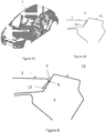
- la
figure 1 représente une vue en coupe de la partie supérieure d'un côté de caisse sur lequel est assemblé un pavillon de toit selon un procédé d'assemblage par soudobrasage laser ; - les
figures 2a ,2b ,2c et2d représentent respectivement une caisse de véhicule sur laquelle est assemblé un pavillon selon les différentes étapes du procédé d'assemblage selon l'invention ; - les
figures 3a ,3b ,3c et3d représentent respectivement une vue en coupe de la partie supérieure de la caisse selon la ligne de coupe A-A et B-B desfigures 2a ,2b ,2c ,2d . - la
figure 4 représente une vue en coupe de la partie supérieure d'un côté de caisse sur laquelle est assemblé un pavillon selon le procédé d'assemblage selon l'invention.
- the
figure 1 represents a sectional view of the upper part of a body side on which a roof horn is assembled according to a method of assembling by laser brazing; - the
Figures 2a ,2b ,2c and2d represent respectively a vehicle body on which is assembled a flag according to the various steps of the assembly method according to the invention; - the
figures 3a ,3b ,3c and3d respectively represent a sectional view of the upper part of the body according to the section line AA and BB of theFigures 2a ,2b ,2c ,2d . - the
figure 4 represents a sectional view of the upper part of a body side on which is assembled a flag according to the assembly method according to the invention.
Comme cela est visible à la
L'assemblage est alors réalisé par soudo-brasage au laser en déposant un cordon de soudure 4 dans la gorge 3.The assembly is then performed by laser brazing by depositing a
Le procédé selon l'invention permet de proposer sur un pavillon 1 et un côté de caisse 21 similaires, un procédé d'assemblage pouvant se substituer au soudo-brasage par laser sans qu'il soit nécessaire de modifier les éléments à assembler.The method according to the invention makes it possible to propose on a
Comme cela est visible aux
Ce cordon de colle 5 est en outre déposé le long du côté de caisse 21 de sorte que lorsque le pavillon 1 est déposé dessus (cf
En variante, on pourrait également déposer le cordon de colle 5 selon une ligne d'encollage discontinue le long de l'extrémité libre 13 du bord 11 du pavillon 1.Alternatively, it would also be possible to deposit the
Ainsi, le cordon de colle de structure déposé est discontinu pour laisser des zones où lors de la phase suivante la colle ne sera pas présente sous le cordon de soudage TIG afin d'éviter sa destruction
La colle structurelle n'est fonctionnelle qu'après sa polymérisation, celle-ci n'intervenant qu'après le traitement thermique constitué par le passage de la caisse en cataphorèse, par exemple.Thus, the bead of structural adhesive deposited is discontinuous to leave areas where in the next phase the glue will not be present under the TIG welding bead to prevent its destruction
The structural adhesive is functional after its polymerization, the latter intervening only after the heat treatment consisting of the passage of the body in cataphoresis, for example.
Des points de soudage électrique maintiennent le pavillon à l'avant et l'arrière du pavillon.Electrical welding points hold the flag at the front and back of the roof.
De manière à maintenir immobiles le pavillon 1 et la caisse de véhicule 2 jusqu'au passage en cataphorèse, on réalise des points de soudure à la jonction entre eux. Ces points de soudure participent également à la prestation mécanique de l'assemblage mais ils permettent surtout d'éviter tous les mouvements potentiels entre le pavillon 1 et la caisse 2 jusqu'au passage en cataphorèse
Ces points de soudure 6 sont constitués de cordons de soudure obtenus à l'aide d'un soudage à l'arc électrique tel qu'avec une électrode non fusible du type soudage TIG (Tungsten Inert Gas).In order to keep the
These weld points 6 consist of weld seams obtained by means of an electric arc welding such as with a non-fusible electrode of TIG (Tungsten Inert Gas) welding type.
Les cordons de soudure TIG 6 par exemple sont déposés dans le fond de la gorge 3 à la jonction du pavillon 1 et du côté de caisse 21 sur les tronçons de cette jonction correspondant aux zones exemptes de colle de la ligne d'encollage discontinue. De cette manière, on évite tous risques d'émanations liées à la brûlure de la colle et on évite également la détérioration du collage. On réalise de préférence des cordons TIG de 10 à 15mm le long du pavillon afin d'assurer le maintien de celui-ci. Ainsi la géométrie du pavillon est figée.The
Une fois, les points de soudure 6 réalisés, on passe la caisse en cataphorèse. La colle sous l'effet de la température en cataphorèse polymérise.Once the soldering points 6 have been made, the body is cataphoresed. The glue under the effect of the temperature in cataphoresis polymerizes.
Après passage en cataphorèse (ou durcissement à l'air dans le cas d'une colle bi-composant), on dépose dans la gorge 3 tout du long de celle-ci un joint d'étanchéité 7 tel qu'une colle type en PVC ou du mastic qui permet de garantir à la fois l'étanchéité de l'assemblage et l'aspect du joint par lissage, voir les
Sur la
Un procédé selon l'invention permet une solution très économique d'assemblage de ces éléments. Cette solution est manuelle et simple à mettre en oeuvre et permet d'éviter l'utilisation d'autres procédés d'assemblage plus coûteux comme le soudobrasage laser, dont certains sites ne sont pas équipés.A method according to the invention allows a very economical solution of assembly of these elements. This solution is manual and easy to implement and avoids the use of other more expensive assembly methods such as laser brazing, some sites are not equipped.
Claims (10)
- Assembly method for assembling together two sheet metal elements (1, 2), the edge (11) of the first element (1) being shaped to come to bear against the second element (2), forming an assembly region defined at least by the free end (13) of the edge (11) of the first element (1), while, on the opposite side of the assembly region from said free end (13) of the edge (11) of the first element (1), both the first and the second elements extend beyond said assembly region, said assembly method being characterized in that it comprises:depositing a bead of adhesive (5) on one of the elements (1, 2), so that, while the two elements (1, 2) are being assembled together, the adhesive application line along which the adhesive is applied is positioned between the two elements (1, 2), at the assembly region, preferably along the free end (13) of the edge (11) of the first element (1); and thenperforming welding to form at least one weld between the two elements (1, 2) along the edge of the assembly region that is opposite from the edge of the assembly region that is constituted by the free end (13) of the edge (11) of the first element (1), this fastening by welding making it possible to hold the two elements stationary relative to each other until a step of hardening the adhesive takes place that finalizes the assembly.
- Assembly method according to claim 1, characterized in that the adhesive is deposited in a discontinuous line, the adhesive application line having segments devoid of adhesive.
- Assembly method according to claim 1, characterized in that the welding is performed, discontinuously, at segments of the assembly region that are devoid of adhesive.
- Assembly method according to any one of claims 1 to 3, characterized in that the first element (1) is assembled to the second element (2) by forming a region, defined by the free end (13) of the edge (11) of the first element (1), while, opposite from the free end of the edge of the first element (1), the two elements (1, 2) extend beyond said region while diverging from each other and while forming a groove (3) between them in which at least one bead of welding is formed.
- Method according to any one of claims 1 to 3, characterized in that the first element has a dropped edge designed to come to bear against the second element, the assembly region being defined by the free end of the dropped edge and by the fold forming said dropped edge, at least one bead of welding being provided at the junction between the first element and the second element at the fold of the first element.
- Method according to any one of claims 1 to 4, characterized in that the first element has a curved-back edge (11), of which the curved portion (12) as brought into abutment against the second element (2) forms a junction in the shape of a groove (3) with said second element (2), while the free end (13) of the curved-back edge (11) is designed to extend, substantially beyond the junction, along the second element (21), forming the assembly region, at least one bead of welding (6) being provided in the groove (3) formed between the first element (1) and the second element (2).
- Method according to any one of claims 1 to 6, characterized in that the welding is electric arc welding such as electric arc welding with a non-consumable electrode of the Tungsten Inert Gas (TIG) welding type.
- Method according to any one of claims 1 to 7, characterized in that a continuous bead of sealant (7) such as a seal of adhesive of the polyvinyl chloride (PVC) adhesive sealant type is also deposited along the edge of the assembly region as provided with at least one bead of welding.
- Assembly of two sheet metal elements (1, 2), the edge (11) of the first element (1) being shaped to come to bear against the second element (2), forming an assembly region defined at least by the free end (13) of the edge (11) of the first element (1), while, on the opposite side of the assembly region from the free end (13) of the edge (11) of the first element (1), both the first and the second elements (1, 2) extend beyond said assembly region, said assembly being characterized in that the edge (11) of the first element (1) is assembled to the second element (2) by at least one bead of adhesive (5) extending, at the assembly region, along the free end (13) of the edge (11) of the first element (1), and by at least one weld (6) between the two elements (1, 2) along the edge of the assembly region that is opposite from the edge of the assembly region that is constituted by the free end (13) of the edge (11) of the first element (1).
- Automotive vehicle having a roof that is assembled to the sides of a body using an assembly method according to any one of claims 1 to 3 and 6 to 8.
Applications Claiming Priority (2)
| Application Number | Priority Date | Filing Date | Title |
|---|---|---|---|
| FR1558846A FR3041319B1 (en) | 2015-09-18 | 2015-09-18 | METHOD OF ASSEMBLY BETWEEN TWO ELEMENTS IN METALLIC SHEET |
| PCT/FR2016/052283 WO2017046494A1 (en) | 2015-09-18 | 2016-09-09 | Assembly method between two elements made of sheet metal |
Publications (2)
| Publication Number | Publication Date |
|---|---|
| EP3350066A1 EP3350066A1 (en) | 2018-07-25 |
| EP3350066B1 true EP3350066B1 (en) | 2019-08-28 |
Family
ID=54366438
Family Applications (1)
| Application Number | Title | Priority Date | Filing Date |
|---|---|---|---|
| EP16774527.2A Active EP3350066B1 (en) | 2015-09-18 | 2016-09-09 | Assembly method between two elements made of sheet metal |
Country Status (3)
| Country | Link |
|---|---|
| EP (1) | EP3350066B1 (en) |
| FR (1) | FR3041319B1 (en) |
| WO (1) | WO2017046494A1 (en) |
Family Cites Families (6)
| Publication number | Priority date | Publication date | Assignee | Title |
|---|---|---|---|---|
| US7004536B2 (en) * | 2002-07-29 | 2006-02-28 | L&L Products, Inc. | Attachment system and method of forming same |
| DE10309634A1 (en) * | 2003-03-04 | 2004-09-23 | Audi Ag | Sheet metal molded part and method for producing a sheet metal molded part |
| DE102004016849B4 (en) * | 2004-04-07 | 2007-12-13 | Dr.Ing.H.C. F. Porsche Ag | Vehicle structure of a motor vehicle |
| FR2943266B1 (en) * | 2009-03-17 | 2013-07-05 | Peugeot Citroen Automobiles Sa | SUDOBRASING DEVICE |
| JP5240027B2 (en) * | 2009-04-09 | 2013-07-17 | マツダ株式会社 | Metal plate joint structure |
| JP5614488B2 (en) * | 2011-03-01 | 2014-10-29 | トヨタ自動車株式会社 | Adhesive flange structure |
-
2015
- 2015-09-18 FR FR1558846A patent/FR3041319B1/en not_active Expired - Fee Related
-
2016
- 2016-09-09 WO PCT/FR2016/052283 patent/WO2017046494A1/en unknown
- 2016-09-09 EP EP16774527.2A patent/EP3350066B1/en active Active
Non-Patent Citations (1)
| Title |
|---|
| None * |
Also Published As
| Publication number | Publication date |
|---|---|
| FR3041319B1 (en) | 2017-10-06 |
| EP3350066A1 (en) | 2018-07-25 |
| FR3041319A1 (en) | 2017-03-24 |
| WO2017046494A1 (en) | 2017-03-23 |
Similar Documents
| Publication | Publication Date | Title |
|---|---|---|
| EP3137252B1 (en) | Method of assembly by discontinuous thermal welding along the join of a steel sheet with an aluminium sheet, with deposition of a clean material to form a sealed joint on the join ; corresponding assembly | |
| FR2971191A1 (en) | Method for assembling plastic parts e.g. decorative medallion, seal housing and thin carrier part, at door panel of motor vehicle, involves providing part with relief projection that is melt at stage of creating welded connection | |
| EP3272616B1 (en) | Assembly process of a carbodyshell | |
| EP3194104B1 (en) | Method of assembling two sheet metal components such as vehicle bodywork components | |
| EP3350066B1 (en) | Assembly method between two elements made of sheet metal | |
| FR2918014A1 (en) | Structure for supporting and sealing a housing of rear light of a motor vehicle, comprises a part forming passenger compartment side of a rear flange and a lower closure part of the rear flange on which the housing is fixed | |
| EP2307166B1 (en) | Brazing method for fastening two workpieces together | |
| EP3030371B1 (en) | Process of welding together by arc or laser welding two superposed edges of two sheets made of aluminium or galvanised steel | |
| EP3922511B1 (en) | Method for attachment by welding of an interface support on a profile of a vehicle seat rail | |
| EP2408585B1 (en) | Braze-welding device | |
| EP0053053B1 (en) | Sun visor, especially for vehicles | |
| FR2903369A3 (en) | Motor vehicle`s roof assembling method, involves folding edge by wheel or die, to define section with wings, and connecting free wing to shoulder by gum layer or welding realized between ends of free wing and one of sheets, respectively | |
| EP1491807B1 (en) | Pipe connection element | |
| FR2958571A1 (en) | Assembling two sheet parts e.g. body shell of an automobile vehicle by braze welding, comprises disposing metal wire at seam of parts to be assembled and melting wire using infrared radiation heat source to form solder fillet between parts | |
| EP0711614B1 (en) | Method for assembling two metal banks | |
| EP3917806B1 (en) | Vehicle comprising a window cover assembly assembled by clinching | |
| FR3072140B1 (en) | METHOD FOR ASSEMBLING METAL SHEET ELEMENTS | |
| EP3144126A1 (en) | Weldable profile member and associated method, for welding plastic panels | |
| EP1762798A1 (en) | Production method of a tank which is to be integrated in a heat exchanger | |
| WO2023062296A1 (en) | Method for joining two sheet-metal parts together by adhesive bonding and welding | |
| EP2906385B1 (en) | Welding method for assembling an aluminium sheet having a port with a steel sheet | |
| EP2626481B1 (en) | Top clip for standing seam roof | |
| FR2793433A1 (en) | Assembly by welding of hollow aluminum parts of motor vehicle bodywork with reduced deformation | |
| FR2896755A1 (en) | BREAKAGE CAP ASSEMBLY AND METHOD OF MANUFACTURING SUCH AMOUNT. | |
| FR3040907A1 (en) | WELDABLE PROFILE AND ASSOCIATED METHOD FOR WELDING PANELS OF PLASTIC MATERIAL |
Legal Events
| Date | Code | Title | Description |
|---|---|---|---|
| STAA | Information on the status of an ep patent application or granted ep patent |
Free format text: STATUS: THE INTERNATIONAL PUBLICATION HAS BEEN MADE |
|
| PUAI | Public reference made under article 153(3) epc to a published international application that has entered the european phase |
Free format text: ORIGINAL CODE: 0009012 |
|
| STAA | Information on the status of an ep patent application or granted ep patent |
Free format text: STATUS: REQUEST FOR EXAMINATION WAS MADE |
|
| 17P | Request for examination filed |
Effective date: 20180220 |
|
| AK | Designated contracting states |
Kind code of ref document: A1 Designated state(s): AL AT BE BG CH CY CZ DE DK EE ES FI FR GB GR HR HU IE IS IT LI LT LU LV MC MK MT NL NO PL PT RO RS SE SI SK SM TR |
|
| AX | Request for extension of the european patent |
Extension state: BA ME |
|
| DAX | Request for extension of the european patent (deleted) | ||
| RAV | Requested validation state of the european patent: fee paid |
Extension state: MA Effective date: 20180220 |
|
| GRAP | Despatch of communication of intention to grant a patent |
Free format text: ORIGINAL CODE: EPIDOSNIGR1 |
|
| STAA | Information on the status of an ep patent application or granted ep patent |
Free format text: STATUS: GRANT OF PATENT IS INTENDED |
|
| INTG | Intention to grant announced |
Effective date: 20190325 |
|
| GRAS | Grant fee paid |
Free format text: ORIGINAL CODE: EPIDOSNIGR3 |
|
| GRAA | (expected) grant |
Free format text: ORIGINAL CODE: 0009210 |
|
| STAA | Information on the status of an ep patent application or granted ep patent |
Free format text: STATUS: THE PATENT HAS BEEN GRANTED |
|
| AK | Designated contracting states |
Kind code of ref document: B1 Designated state(s): AL AT BE BG CH CY CZ DE DK EE ES FI FR GB GR HR HU IE IS IT LI LT LU LV MC MK MT NL NO PL PT RO RS SE SI SK SM TR |
|
| REG | Reference to a national code |
Ref country code: GB Ref legal event code: FG4D Free format text: NOT ENGLISH |
|
| REG | Reference to a national code |
Ref country code: CH Ref legal event code: EP |
|
| REG | Reference to a national code |
Ref country code: DE Ref legal event code: R096 Ref document number: 602016019534 Country of ref document: DE |
|
| REG | Reference to a national code |
Ref country code: AT Ref legal event code: REF Ref document number: 1172049 Country of ref document: AT Kind code of ref document: T Effective date: 20190915 |
|
| REG | Reference to a national code |
Ref country code: IE Ref legal event code: FG4D Free format text: LANGUAGE OF EP DOCUMENT: FRENCH |
|
| REG | Reference to a national code |
Ref country code: SK Ref legal event code: T3 Ref document number: E 31989 Country of ref document: SK |
|
| REG | Reference to a national code |
Ref country code: NL Ref legal event code: MP Effective date: 20190828 |
|
| REG | Reference to a national code |
Ref country code: LT Ref legal event code: MG4D |
|
| REG | Reference to a national code |
Ref country code: DE Ref legal event code: R084 Ref document number: 602016019534 Country of ref document: DE |
|
| PG25 | Lapsed in a contracting state [announced via postgrant information from national office to epo] |
Ref country code: NO Free format text: LAPSE BECAUSE OF FAILURE TO SUBMIT A TRANSLATION OF THE DESCRIPTION OR TO PAY THE FEE WITHIN THE PRESCRIBED TIME-LIMIT Effective date: 20191128 Ref country code: SE Free format text: LAPSE BECAUSE OF FAILURE TO SUBMIT A TRANSLATION OF THE DESCRIPTION OR TO PAY THE FEE WITHIN THE PRESCRIBED TIME-LIMIT Effective date: 20190828 Ref country code: FI Free format text: LAPSE BECAUSE OF FAILURE TO SUBMIT A TRANSLATION OF THE DESCRIPTION OR TO PAY THE FEE WITHIN THE PRESCRIBED TIME-LIMIT Effective date: 20190828 Ref country code: HR Free format text: LAPSE BECAUSE OF FAILURE TO SUBMIT A TRANSLATION OF THE DESCRIPTION OR TO PAY THE FEE WITHIN THE PRESCRIBED TIME-LIMIT Effective date: 20190828 Ref country code: PT Free format text: LAPSE BECAUSE OF FAILURE TO SUBMIT A TRANSLATION OF THE DESCRIPTION OR TO PAY THE FEE WITHIN THE PRESCRIBED TIME-LIMIT Effective date: 20191230 Ref country code: LT Free format text: LAPSE BECAUSE OF FAILURE TO SUBMIT A TRANSLATION OF THE DESCRIPTION OR TO PAY THE FEE WITHIN THE PRESCRIBED TIME-LIMIT Effective date: 20190828 Ref country code: BG Free format text: LAPSE BECAUSE OF FAILURE TO SUBMIT A TRANSLATION OF THE DESCRIPTION OR TO PAY THE FEE WITHIN THE PRESCRIBED TIME-LIMIT Effective date: 20191128 Ref country code: NL Free format text: LAPSE BECAUSE OF FAILURE TO SUBMIT A TRANSLATION OF THE DESCRIPTION OR TO PAY THE FEE WITHIN THE PRESCRIBED TIME-LIMIT Effective date: 20190828 |
|
| PG25 | Lapsed in a contracting state [announced via postgrant information from national office to epo] |
Ref country code: AL Free format text: LAPSE BECAUSE OF FAILURE TO SUBMIT A TRANSLATION OF THE DESCRIPTION OR TO PAY THE FEE WITHIN THE PRESCRIBED TIME-LIMIT Effective date: 20190828 Ref country code: ES Free format text: LAPSE BECAUSE OF FAILURE TO SUBMIT A TRANSLATION OF THE DESCRIPTION OR TO PAY THE FEE WITHIN THE PRESCRIBED TIME-LIMIT Effective date: 20190828 Ref country code: GR Free format text: LAPSE BECAUSE OF FAILURE TO SUBMIT A TRANSLATION OF THE DESCRIPTION OR TO PAY THE FEE WITHIN THE PRESCRIBED TIME-LIMIT Effective date: 20191129 Ref country code: LV Free format text: LAPSE BECAUSE OF FAILURE TO SUBMIT A TRANSLATION OF THE DESCRIPTION OR TO PAY THE FEE WITHIN THE PRESCRIBED TIME-LIMIT Effective date: 20190828 Ref country code: RS Free format text: LAPSE BECAUSE OF FAILURE TO SUBMIT A TRANSLATION OF THE DESCRIPTION OR TO PAY THE FEE WITHIN THE PRESCRIBED TIME-LIMIT Effective date: 20190828 Ref country code: IS Free format text: LAPSE BECAUSE OF FAILURE TO SUBMIT A TRANSLATION OF THE DESCRIPTION OR TO PAY THE FEE WITHIN THE PRESCRIBED TIME-LIMIT Effective date: 20191228 |
|
| REG | Reference to a national code |
Ref country code: GB Ref legal event code: 746 Effective date: 20200207 |
|
| REG | Reference to a national code |
Ref country code: AT Ref legal event code: MK05 Ref document number: 1172049 Country of ref document: AT Kind code of ref document: T Effective date: 20190828 |
|
| PG25 | Lapsed in a contracting state [announced via postgrant information from national office to epo] |
Ref country code: TR Free format text: LAPSE BECAUSE OF FAILURE TO SUBMIT A TRANSLATION OF THE DESCRIPTION OR TO PAY THE FEE WITHIN THE PRESCRIBED TIME-LIMIT Effective date: 20190828 |
|
| PG25 | Lapsed in a contracting state [announced via postgrant information from national office to epo] |
Ref country code: RO Free format text: LAPSE BECAUSE OF FAILURE TO SUBMIT A TRANSLATION OF THE DESCRIPTION OR TO PAY THE FEE WITHIN THE PRESCRIBED TIME-LIMIT Effective date: 20190828 Ref country code: PL Free format text: LAPSE BECAUSE OF FAILURE TO SUBMIT A TRANSLATION OF THE DESCRIPTION OR TO PAY THE FEE WITHIN THE PRESCRIBED TIME-LIMIT Effective date: 20190828 Ref country code: EE Free format text: LAPSE BECAUSE OF FAILURE TO SUBMIT A TRANSLATION OF THE DESCRIPTION OR TO PAY THE FEE WITHIN THE PRESCRIBED TIME-LIMIT Effective date: 20190828 Ref country code: AT Free format text: LAPSE BECAUSE OF FAILURE TO SUBMIT A TRANSLATION OF THE DESCRIPTION OR TO PAY THE FEE WITHIN THE PRESCRIBED TIME-LIMIT Effective date: 20190828 Ref country code: IT Free format text: LAPSE BECAUSE OF FAILURE TO SUBMIT A TRANSLATION OF THE DESCRIPTION OR TO PAY THE FEE WITHIN THE PRESCRIBED TIME-LIMIT Effective date: 20190828 Ref country code: DK Free format text: LAPSE BECAUSE OF FAILURE TO SUBMIT A TRANSLATION OF THE DESCRIPTION OR TO PAY THE FEE WITHIN THE PRESCRIBED TIME-LIMIT Effective date: 20190828 |
|
| PG25 | Lapsed in a contracting state [announced via postgrant information from national office to epo] |
Ref country code: MC Free format text: LAPSE BECAUSE OF FAILURE TO SUBMIT A TRANSLATION OF THE DESCRIPTION OR TO PAY THE FEE WITHIN THE PRESCRIBED TIME-LIMIT Effective date: 20190828 Ref country code: IS Free format text: LAPSE BECAUSE OF FAILURE TO SUBMIT A TRANSLATION OF THE DESCRIPTION OR TO PAY THE FEE WITHIN THE PRESCRIBED TIME-LIMIT Effective date: 20200224 Ref country code: CZ Free format text: LAPSE BECAUSE OF FAILURE TO SUBMIT A TRANSLATION OF THE DESCRIPTION OR TO PAY THE FEE WITHIN THE PRESCRIBED TIME-LIMIT Effective date: 20190828 Ref country code: SM Free format text: LAPSE BECAUSE OF FAILURE TO SUBMIT A TRANSLATION OF THE DESCRIPTION OR TO PAY THE FEE WITHIN THE PRESCRIBED TIME-LIMIT Effective date: 20190828 |
|
| REG | Reference to a national code |
Ref country code: CH Ref legal event code: PL |
|
| REG | Reference to a national code |
Ref country code: DE Ref legal event code: R097 Ref document number: 602016019534 Country of ref document: DE |
|
| PLBE | No opposition filed within time limit |
Free format text: ORIGINAL CODE: 0009261 |
|
| STAA | Information on the status of an ep patent application or granted ep patent |
Free format text: STATUS: NO OPPOSITION FILED WITHIN TIME LIMIT |
|
| PG2D | Information on lapse in contracting state deleted |
Ref country code: IS |
|
| PG25 | Lapsed in a contracting state [announced via postgrant information from national office to epo] |
Ref country code: LI Free format text: LAPSE BECAUSE OF NON-PAYMENT OF DUE FEES Effective date: 20190930 Ref country code: IE Free format text: LAPSE BECAUSE OF NON-PAYMENT OF DUE FEES Effective date: 20190909 Ref country code: LU Free format text: LAPSE BECAUSE OF NON-PAYMENT OF DUE FEES Effective date: 20190909 Ref country code: CH Free format text: LAPSE BECAUSE OF NON-PAYMENT OF DUE FEES Effective date: 20190930 |
|
| REG | Reference to a national code |
Ref country code: BE Ref legal event code: MM Effective date: 20190930 |
|
| 26N | No opposition filed |
Effective date: 20200603 |
|
| PG25 | Lapsed in a contracting state [announced via postgrant information from national office to epo] |
Ref country code: SI Free format text: LAPSE BECAUSE OF FAILURE TO SUBMIT A TRANSLATION OF THE DESCRIPTION OR TO PAY THE FEE WITHIN THE PRESCRIBED TIME-LIMIT Effective date: 20190828 Ref country code: BE Free format text: LAPSE BECAUSE OF NON-PAYMENT OF DUE FEES Effective date: 20190930 |
|
| PG25 | Lapsed in a contracting state [announced via postgrant information from national office to epo] |
Ref country code: CY Free format text: LAPSE BECAUSE OF FAILURE TO SUBMIT A TRANSLATION OF THE DESCRIPTION OR TO PAY THE FEE WITHIN THE PRESCRIBED TIME-LIMIT Effective date: 20190828 |
|
| VS25 | Lapsed in a validation state [announced via postgrant information from nat. office to epo] |
Ref country code: MA Free format text: LAPSE BECAUSE OF FAILURE TO SUBMIT A TRANSLATION OF THE DESCRIPTION OR TO PAY THE FEE WITHIN THE PRESCRIBED TIME-LIMIT Effective date: 20190828 |
|
| PG25 | Lapsed in a contracting state [announced via postgrant information from national office to epo] |
Ref country code: HU Free format text: LAPSE BECAUSE OF FAILURE TO SUBMIT A TRANSLATION OF THE DESCRIPTION OR TO PAY THE FEE WITHIN THE PRESCRIBED TIME-LIMIT; INVALID AB INITIO Effective date: 20160909 Ref country code: MT Free format text: LAPSE BECAUSE OF FAILURE TO SUBMIT A TRANSLATION OF THE DESCRIPTION OR TO PAY THE FEE WITHIN THE PRESCRIBED TIME-LIMIT Effective date: 20190828 |
|
| PG25 | Lapsed in a contracting state [announced via postgrant information from national office to epo] |
Ref country code: MK Free format text: LAPSE BECAUSE OF FAILURE TO SUBMIT A TRANSLATION OF THE DESCRIPTION OR TO PAY THE FEE WITHIN THE PRESCRIBED TIME-LIMIT Effective date: 20190828 |
|
| PGFP | Annual fee paid to national office [announced via postgrant information from national office to epo] |
Ref country code: GB Payment date: 20230823 Year of fee payment: 8 |
|
| PGFP | Annual fee paid to national office [announced via postgrant information from national office to epo] |
Ref country code: SK Payment date: 20230830 Year of fee payment: 8 Ref country code: FR Payment date: 20230822 Year of fee payment: 8 Ref country code: DE Payment date: 20230822 Year of fee payment: 8 |