EP0052882B1 - Shower enclosure - Google Patents
Shower enclosure Download PDFInfo
- Publication number
- EP0052882B1 EP0052882B1 EP19810109848 EP81109848A EP0052882B1 EP 0052882 B1 EP0052882 B1 EP 0052882B1 EP 19810109848 EP19810109848 EP 19810109848 EP 81109848 A EP81109848 A EP 81109848A EP 0052882 B1 EP0052882 B1 EP 0052882B1
- Authority
- EP
- European Patent Office
- Prior art keywords
- guide
- guide beam
- separator according
- shower
- frame
- Prior art date
- Legal status (The legal status is an assumption and is not a legal conclusion. Google has not performed a legal analysis and makes no representation as to the accuracy of the status listed.)
- Expired
Links
- 238000004140 cleaning Methods 0.000 claims description 9
- XLYOFNOQVPJJNP-UHFFFAOYSA-N water Substances O XLYOFNOQVPJJNP-UHFFFAOYSA-N 0.000 claims description 9
- 238000006073 displacement reaction Methods 0.000 claims description 3
- 239000004033 plastic Substances 0.000 claims description 3
- 229920003023 plastic Polymers 0.000 claims description 3
- 239000000463 material Substances 0.000 claims description 2
- 230000000717 retained effect Effects 0.000 claims description 2
- 230000006835 compression Effects 0.000 claims 1
- 238000007906 compression Methods 0.000 claims 1
- 238000001125 extrusion Methods 0.000 claims 1
- 238000005192 partition Methods 0.000 description 22
- 238000005452 bending Methods 0.000 description 3
- 239000011324 bead Substances 0.000 description 2
- 238000010276 construction Methods 0.000 description 1
- 230000001419 dependent effect Effects 0.000 description 1
- 238000000034 method Methods 0.000 description 1
- 230000002093 peripheral effect Effects 0.000 description 1
- 230000000284 resting effect Effects 0.000 description 1
Images


Classifications
-
- A—HUMAN NECESSITIES
- A47—FURNITURE; DOMESTIC ARTICLES OR APPLIANCES; COFFEE MILLS; SPICE MILLS; SUCTION CLEANERS IN GENERAL
- A47K—SANITARY EQUIPMENT NOT OTHERWISE PROVIDED FOR; TOILET ACCESSORIES
- A47K3/00—Baths; Douches; Appurtenances therefor
- A47K3/28—Showers or bathing douches
- A47K3/30—Screens or collapsible cabinets for showers or baths
- A47K3/34—Slidable screens
Definitions
- the invention relates to a shower partition with a lower guide for sliding partitions, which are suspended within a frame in an upper slide rail and with their lower guide strips in an upwardly open, delimited by two lateral guide walls, an elongated, lower, between the lateral guide slots Immerse parts of the frame attached guide body, the front fixed guide wall has a water drainage leg drawn towards the damp room and the rear, moisture-side side is designed as a guide rail which is movably supported with its ends from the area of the lower ends of the partition walls.
- the object of the present invention is to provide an easier-to-use design of the movable guide bar, while avoiding such pivoting in several planes.
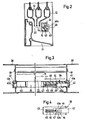
- a frame 10 for shower cubicles according to FIG. 1 has on the underside an approximately L-shaped rail 11, on the short outside leg 11a of which three movable partition walls are guided as sliding doors 12, which are slidably suspended from an upper cross member (not shown) ).
- the leg 11a is bent inward in a U-shape.
- Another, longer leg 11b serves as a water drain leg and is directed towards the shower room (damp room).
- the lower elongated L-shaped rail 11 is fixed between two side U-shaped frames 13 by means of a screw and plug connection.
- a guide bar 15 according to FIG. 1 is releasably attached to the ends of the L-shaped rail 11 as a rear guide wall on the damp side.
- the lower ends 14 of the partition walls dip into a guide slot 22 which is formed on the one hand by the leg 11a of the front guide wall and on the other hand by the movable guide bar 15.
- the guide bar 15 can be removed quickly and effortlessly in a few simple steps, so that the sliding doors 12 are also pivoted into the damp room and thus the guide surfaces of the rail 11 can be cleaned. After completion of the cleaning process, the guide bar 15 can be easily integrated again.
- the L-shaped lower rail 11 is connected to two lateral I-shaped frame parts 38 by means of screws 18; these frame parts 38 hold the guide bar 15, in which a latching device 39 is fastened at one end and a plug pin 40 is fastened at the other end, which engage in end caps 41 with recesses 41a of the frame parts 38.
- the plug pin 40 is inserted in the guide bar 15 in a clamping manner and has a nose 40a.
- the latching device 39 is fastened in the guide bar 15, the catch (latch) 42 of which also engages in the end cap 41 or the recess 41a thereof.
- the latching device consists of the latch 42, which is mounted displaceably in a plug pin 43 and is limited in its displacement by means of cams 43a which engage in the recess 44 of the latch 42.
- a plug opening 47 is arranged in the case 42 facing the interior of the cabin, in which a grip piece 48 is held in a clamping manner with a plug part 48a.
- the plug part 48a protrudes from the wall of the guide bar 15 through a slot 49 to the interior, so that the handle 48 is on the outer surface of the guide bar 15 and is therefore easy to operate while overcoming the spring force.
- peripheral frame 51 the side parts 51a of which are preferably formed from U-shaped extruded profiles and on the upper cross member 52, for example, three sliding partitions 53 (sliding doors) are suspended in corresponding slide rails and the Can give access to the wet room (shower cubicle).
- the lower cross member 54 which can rest on the edge of the shower tray, has a front guide wall 55 which runs downward and inward toward the damp room as a water drainage leg 56. Both crossbars 52, 54 are equipped with corresponding grooves 57 in order to connect the side parts 51a into a frame 51 by means of screws 58.
- the partition walls 53 slidably suspended on the upper cross member 52 each have a guide bar 59 on the underside, to which end caps 60 are attached.
- the end caps 60 of the front partition 53 can rest against the front guide wall 55 of the lower cross member 54.
- a guide rail 62 is arranged opposite the guide wall 55 of the lower cross member 54, forming a guide slot 61, which limits the guide strips 59 of the inner partition wall 53.
- the guide bar 62 which is preferably manufactured as an extruded profile, is clamped in the side parts 51a of the U-shaped frame 51.
- the guide bar ends are supported in the cross section of the guide bar 62 by correspondingly designed bushes 63 which are kept inserted in openings 64 of the side parts 51a and hold the guide bar 62 in a clamping manner against displacement.
- This guide bar 62 is preferably made of plastic and has a U-shaped cross section, the free legs 62a of which are directed towards the water leg 56 of the lower cross bar 54 (i.e. downwards).
- the elastically flexible guide bar 62 can be pressed downward in its central part.
- the partitions 53 can now be pivoted away (cf. FIGS. 6 and 8).
- the partition walls 53 are also introduced into the guide slot 61 by bending the guide rail 62 downward until the upper edge of the guide rail 62 lies below the lower edge of the guide rail 59 of the partition walls 53, so that these can then be pivoted in.
- Such a U-shaped plastic guide bar 62 has the advantage that during the bending the free legs 62a partially deform outwards in the bending area, the lateral stability of the guide bar 62 being favorably supported.
- the guide bar 62 is preferably formed by two tube ends 65, which or the like by means of a leaf spring 66. by rivets 67, screws or the like. are interconnected.
- a guide bar 62 designed in this way can be pressed downward at an obtuse angle for pivoting the partition walls 53 for cleaning purposes, the lateral stability being retained by the flat leaf spring 66.
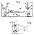
- a guide bar 68 shown in FIGS. 11 and 12 is also U-shaped and has a bent resilient tongue 69 on the underside, which is supported on the water drainage leg 56 of the cross bar 54 or on the tub rim.
- the tongue 69 is preferably formed from the same material of the guide rail 68 and is arranged approximately in the middle in accordance with its length.
- the bearing bushes 70 are rectangular in cross section and can be connected to the side parts 51 a of the frame 52 by means of the screws 58.
- the guide bar 68 is inserted by inserting one end into an opening 70a of the bearing bushes 70 of a side part 51a until the other end lies in front of the opposite opening 70a of the other bearing bushing 70 and can then be inserted.
- the guide bar 68 is held in position by the beads 71.
- the bearing bush 70 shown in FIG. 12 it has an inward and upward slope 72 in the opening 70a, the upper bead 71 resting close to the end of the guide rail.
- the bevel 72 causes the ends to slide out slightly when the guide bar is bent to remove it.
Landscapes
- Health & Medical Sciences (AREA)
- Public Health (AREA)
- Epidemiology (AREA)
- General Health & Medical Sciences (AREA)
- Domestic Plumbing Installations (AREA)
- Support Devices For Sliding Doors (AREA)
Description
Die Erfindung bezieht sich auf eine Duschabtrennung mit einer unteren Führung für verschiebbare Trennwände, die innerhalb eines Rahmens in einer oberen Gleitschiene aufgehängt sind und mit ihren unteren Führungsleisten in einen nach oben offenen, von zwei seitlichen Führungswänden begrenzten Führungsschlitz eines länglichen, unteren, zwischen den seitlichen Teilen des Rahmens befestigten Führungskörpers eintauchen, wobei die vordere feste Führungswand einen zum Feuchtraum gezogenen Wasserablaufschenkel aufweist und die hintere, feuchtraumseitige als Führungsholm ausgebildet ist, der mit seinen Enden aus dem Bereich der unteren Enden der Trennwände heraus beweglich gelagert ist.The invention relates to a shower partition with a lower guide for sliding partitions, which are suspended within a frame in an upper slide rail and with their lower guide strips in an upwardly open, delimited by two lateral guide walls, an elongated, lower, between the lateral guide slots Immerse parts of the frame attached guide body, the front fixed guide wall has a water drainage leg drawn towards the damp room and the rear, moisture-side side is designed as a guide rail which is movably supported with its ends from the area of the lower ends of the partition walls.
Eine derartige Ausführung ist bereits aus der EPA-001612 bekannt, bei welcher der untere Führungsholm an den seitlichen vertikalen Rahmenteilen zum Feuchtraum hin schwenkbar gelagert ist.Such an embodiment is already known from EPA-001612, in which the lower guide bar is pivotally mounted on the lateral vertical frame parts towards the damp room.
Aufgabe der vorliegenden Erfindung ist, unter Vermeidung einer derartigen, in mehreren Ebenen verlaufenden Schwenkbarkeit eine leichter zu handhabende Ausbildung des beweglichen Führungsholmes zu schaffen.The object of the present invention is to provide an easier-to-use design of the movable guide bar, while avoiding such pivoting in several planes.
Diese Aufgabe wird gemäss der Erfindung dadurch gelöst, dass der Führungsholm in Endkappen oder Buchsen, die in den seitlichen Teilen des Rahmens befestigt sind, federnd herausnehmbar eingesteckt gehaltert ist.This object is achieved according to the invention in that the guide bar is inserted in end caps or bushings, which are fastened in the lateral parts of the frame, so as to be resiliently removable.
Weitere Merkmale der Erfindung ergeben sich aus den abhängigen Ansprüchen.Further features of the invention result from the dependent claims.
Die Merkmale der Erfindung sind aufgrund des einfachen konstruktiven Aufbaus ohne Schwierigkeiten und ohne besonderen Aufwand herstellbar. Bei der Benutzung (zur Reinigung) bedarf es nur weniger oder nur eines Handgriffes, um den Führungsholm einerseits aus dem unteren feuchtraumseitigen Bereich der Trennwände zu entfernen oder andererseits nach einer Reinigung in diesen Bereich zurückzubringen. Auf der Zeichnung sind Ausführungsbeispiele der Erfindung dargestellt. Es zeigen:
- Fig. 1 einen senkrechten Schnitt durch den unteren Rahmen einer Duschwand mit Schiebetüren und die Türen begrenzendem lösbaren Führungsholm;
- Fig. 2 einen senkrechten Schnitt eines abgeänderten unteren Rahmens einer Duschwand mit Schiebetüren und lösbarem Führungsholm;
- Fig. 3 eine Draufsicht auf den unteren Rahmen mit im Führungsholm angeordneter Rasteinrichtung teilweise geschnitten;
- Fig. 4 eine Vorderansicht der Rasteinrichtung;
- Fig. 5 eine Seitenansicht einer Duschabtrennung mit verschiebbaren Trennwänden in geschlossener Stellung und untenseitigem Führungsholm;
- Fig. 6 eine Seitenansicht mit in die Mitte des Rahmens zusammengeschobenen Trennwänden und einem weiteren abgeänderten, nach unten durchgebogenen Führungsholm zur Entnahme der Trennwände;
- Fig. 7 eine Draufsicht derselben Duschabtrennung entsprechend der Schnittlinie XII-XII in Fig. 5;
- Fig. 8 einen senkrechten Schnitt des unteren Querholms mit durchgebogenem Führungsholm entsprechend der Schnittlinie XIII-XIII in Fig. 6;
- Fig. 9 eine perspektivische Ansicht des Führungsholms als Strangprofil;
- Fig. 10 eine perspektivische Ansicht eines abgeänderten Führungsholms mit Blattfeder;
- Fig. 11 einen senkrechten Schnitt der Seitenteile des Rahmens mit abgeänderten Lagerbuchsen und Führungsholm und
- Fig. 12 einen senkrechten Schnitt eines Seitenteiles des Rahmens mit weiter abgeänderter Endkappe für den Führungsholm.
- Figure 1 is a vertical section through the lower frame of a shower wall with sliding doors and detachable guide rail limiting the doors.
- Figure 2 is a vertical section of a modified lower frame of a shower wall with sliding doors and detachable guide rail.
- Figure 3 is a plan view of the lower frame with the locking device arranged in the guide bar partially cut.
- Fig. 4 is a front view of the locking device;
- Figure 5 is a side view of a shower partition with sliding partitions in the closed position and the lower guide rail.
- 6 shows a side view with partitions pushed together in the middle of the frame and a further modified guide bar bent downwards for removing the partitions;
- Fig. 7 is a plan view of the same shower partition according to section line XII-XII in Fig. 5;
- Fig. 8 is a vertical section of the lower cross member with a bent guide rail according to section line XIII-XIII in Fig. 6;
- 9 is a perspective view of the guide rail as an extruded profile;
- 10 is a perspective view of a modified guide rail with leaf spring;
- Fig. 11 is a vertical section of the side parts of the frame with modified bearing bushes and guide rail and
- Fig. 12 is a vertical section of a side part of the frame with a further modified end cap for the guide rail.
Ein Rahmen 10 für Duschkabinen gemäss Fig. 1 weist untenseitig eine etwa L-förmige Schiene 11 auf, an deren kurzem aussenseitigen Schenkel 11a als vordere feste Führungswand drei verschiebbare Trennwände als Schiebetüren 12 geführt werden, die an einem oberen Querholm gleitend aufgehängt sind (nicht dargestellt). Zur besseren Führung ist der Schenkel 11a U-förmig nach innen abgebogen. Ein weiterer, längerer Schenkel 11b dient dabei als Wasserablaufschenkel und ist zum Duschraum (Feuchtraum) gerichtet.A
Die untere längliche L-förmige Schiene 11 ist zwischen zwei seitlichen U-förmigen Rahmen 13 mittels Schraub- und Steckverbindung festgesetzt. Um die Schiebetüren 12 mit ihren Führungsleisten 14 in Richtung zum Innenraum zu begrenzen, ist als hintere feuchtraumseitige Führungswand ein Führungsholm 15 gemäss Fig. 1, beispielsweise zum Reinigen, lösbar an den Enden der L-förmigen Schiene 11 befestigt.The lower elongated L-
Die unteren Enden 14 der Trennwände tauchen in einen Führungsschlitz 22 ein, der einerseits durch den Schenkel 11a der vorderen Führungswand und andererseits durch den beweglichen Führungsholm 15 gebildet ist.The
Für die Reinigung des Führungsschlitzes 22 innerhalb der unteren L-förmigen Schiene 11 lässt sich der Führungsholm 15 mit wenigen Handgriffen schnell und mühelos entfernen, so dass die Schiebetüren 12 ebenfalls in den Feuchtraum geschwenkt werden und somit das Reinigen der Führungsflächen der Schiene 11 möglich ist. Nach Beendigung des Reinigungsvorganges kann der Führungsholm 15 wieder einfach integriert werden.For cleaning the
Bei dem Ausführungsbeispiel nach Fig. 2 bis 4 ist die L-förmige untere Schiene 11 zwischen zwei seitlichen I-förmigen Rahmenteilen 38 mittels Schrauben 18 mit diesen verbunden; diese Rahmenteile 38 halten den Führungsholm 15, in dem einenends eine Rasteinrichtung 39 und anderenends ein Steckzapfen 40 befestigt sind, die in Endkappen 41 mitAusnehmungen 41 a der Rahmenteile 38 rastend eingreifen.In the exemplary embodiment according to FIGS. 2 to 4, the L-shaped
Der Steckzapfen 40 ist in dem Führungsholm 15 klemmend eingesteckt und weist eine Nase 40a auf.The
Dem Steckzapfen 40 gegenüberliegend ist in dem Führungsholm 15 die Rasteinrichtung 39 befestigt, deren Falle (Riegel) 42 ebenfalls in die Endkappe 41 bzw. deren Ausnehmung 41a eingreift.Opposing the
Die Rasteinrichtung besteht aus der Falle 42, die in einem Steckzapfen 43 verschiebbar gelagert ist und mittels Nocken 43a, die in Ausnehmung 44 der Falle 42 eingreifen, in seiner Verschiebung begrenzt gehalten wird.The latching device consists of the
In Längsrichtung der Falle 42 liegt in einer Nut 45 eine Feder 46, welche die Falle 42 stets in Raststellung drückt.In the longitudinal direction of the
Um die Raststellung zeitweilig aufzuheben, um den Führungsholm 15 für Reinigungszwecke herausnehmen zu können, ist in der Falle 42 eine Stecköffnung 47 zum Innenraum der Kabine gerichtet angeordnet, in der ein Griffstück 48 mit Steckteil 48a klemmend gehalten ist. Dabei ragt das Steckteil 48a aus der Wandung des Führungsholmes 15 durch einen Schlitz 49 zum Innenraum heraus, so dass das Griffstück 48 an der Aussenfläche des Führungsholms 15 liegt und somit leicht unter Überwindung der Federkraft zu betätigen ist.In order to temporarily release the latching position in order to be able to remove the
Eine Duschabtrennung 50 gemäss Fig. 5 bis 12 weist einen umlaufenden Rahmen 51 auf, dessen Seitenteile 51a aus vorzugsweise U-förmigen Strang-Profilen gebildet sind und an dessen oberem Querholm 52 beispielsweise drei verschiebbare Trennwände 53 (Schiebetüren) in entsprechenden Gleitschienen aufgehängt sind und den Zugang zum Feuchtraum (Duschkabine) freigeben können.5 to 12 has a
Der untere Querholm 54, welcher auf dem Rand der Duschwanne aufliegen kann, weist eine vordere Führungswand 55 auf, die nach unten und innen zum Feuchtraum hin als Wasserablaufschenkel 56 ausläuft. Beide Querholme 52, 54 sind mit entsprechenden Nuten 57 ausgestattet, um in diese die Seitenteile 51a mittels Schrauben 58 zu einem Rahmen 51 zu verbinden.The
Die an dem oberen Querholm 52 verschiebbar aufgehängten Trennwände 53 weisen untenseitig jeweils eine Führungsleiste 59 auf, an denen Endkappen 60 aufgesteckt sind. Dabei können die Endkappen 60 der vorderen Trennwand 53 an der vorderen Führungswand 55 des unteren Querholms 54 anliegen.The
Um die Trennwände 53 auch feuchtraumseitig zu führen, ist der Führungswand 55 des unteren Querholms 54 gegenüberliegend unter Bildung eines Führungsschlitzes 61 ein Führungsholm 62 angeordnet, welcher die Führungsleisten 59 der inneren Trennwand 53 begrenzt.In order to also guide the
Bei diesem Ausführungsbeispiel der Erfindung lagert der vorzugsweise als Strangprofil gefertigte Führungsholm 62 in den Seitenteilen 51a des U-förmigen Rahmens 51 klemmend. Dabei lagern die Führungsholmenden in dem Querschnitt des Führungsholmes 62 entsprechend ausgebildeten Buchsen 63, die in Öffnungen 64 der Seitenteile 51a eingesteckt gehalten sind und den Führungsholm 62 gegen ein Verschieben klemmend halten.In this embodiment of the invention, the
Dieser Führungsholm 62 ist vorzugsweise aus Kunststoff hergestellt und weist einen U-förmigen Querschnitt auf, dessen freie Schenkel 62a zum Wasserschenkel 56 des unteren Querholms 54 (d.h. nach unten) gerichtet sind.This
Sollen bei einem derartigen gehaltenen Führungsholm 62 die Trennwände 53 beispielsweise für Reinigungszwecke aus dem Führungsschlitz 61 nach innen zum Feuchtraum hin verschwenkt werden, so lässt sich der elastisch nachgiebige Führungsholm 62 in seinem Mittelteil nach unten drücken. Nachdem die Trennwände 53 bereits zur Mitte des Rahmens 51 verschoben wurden, können nun die Trennwände 53 abgeschwenkt werden (vgl. Fig. 6 und 8). Das Einbringen der Trennwände 53 in den Führungsschlitz 61 erfolgt ebenfalls durch Durchbiegen des Führungsholmes 62 nach unten, bis die Oberkante des Führungsholmes 62 unter die Unterkante der Führungsleiste 59 der Trennwände 53 liegt, so dass diese dann eingeschwenkt werden können.If the
Ein derartig U-förmig aus Kunststoff gebildeter Führungsholm 62 zeigt den Vorteil, dass während des Durchbiegens die freien Schenkel 62a sich teilweise im Biegungsbereich nach aussen verformen, wobei die Seitenstabilität des Führungsholmes 62 günstig unterstützt wird.Such a U-shaped
Bei dem nach Fig. 10 der Zeichnung dargestellten Ausführungsbeispiel ist der Führungsholm 62 von vorzugsweise zwei Rohrenden 65 gebildet, welche mittels einer Blattfeder 66 o.dgl. durch Nieten 67, Schrauben o.dgl. miteinander verbunden sind.In the embodiment shown in FIG. 10 of the drawing, the
Ein derartig ausgebildeter Führungsholm 62 lässt sich zum Abschwenken der Trennwände 53 für Reinigungszwecke stumpfwinklig nach unten drücken, wobei durch die flach liegende Blattfeder 66 die Seitenstabilität erhalten bleibt.A
Ein in Fig. 11 und 12 gezeigter Führungsholm 68 ist ebenfalls U-förmig ausgebildet und weist untenseitig eine abgebogene federnde Zunge 69 auf, welche sich auf dem Wasserablaufschenkel 56 des Querholms 54 oder aber auf dem Wannenrand abstützt.A
Die Zunge 69 ist vorzugsweise aus demselben Material des Führungsholms 68 gebildet und ist entsprechend seiner Länge etwa mittig angeordnet.The
Desweiteren sind die Lagerbuchsen 70 im Querschnitt rechteckig ausgebildet und lassen sich mittels der Schrauben 58 mit den Seitenteilen 51 a des Rahmens 52 verbinden. Das Einsetzen des Führungsholms 68 erfolgt durch Einstecken eines Endes in eine Öffnung 70a der Lagerbuchsen 70 eines Seitenteils 51a, bis das andere Ende vor der gegenüberliegenden Öffnung 70a der anderen Lagerbuchse 70 liegt und dann eingeschoben werden kann. Der Führungsholm 68 wird dabei über die Wülste 71 in seiner Lage klemmend gehalten.Furthermore, the bearing
Bei der in Fig. 12 dargestellten Lagerbuchse 70 weist diese in der Öffnung 70a eine nach innen und oben auslaufende Schräge 72 auf, wobei die obere Wulst 71 nahe dem Führungsholmende aufliegt. Die Schräge 72 bewirkt bei einem Anheben des Führungsholms 68 nach oben ein leichtes Herausgleiten der Enden bei durchgebogenem Führungsholm zu seiner Entnahme.In the case of the bearing
Claims (8)
Priority Applications (1)
| Application Number | Priority Date | Filing Date | Title |
|---|---|---|---|
| AT81109848T ATE23103T1 (en) | 1980-11-25 | 1981-11-24 | SHOWER ENCLOSURE. |
Applications Claiming Priority (4)
| Application Number | Priority Date | Filing Date | Title |
|---|---|---|---|
| DE8031363 | 1980-11-25 | ||
| DE8031363U | 1980-11-25 | ||
| DE8120556U | 1981-07-14 | ||
| DE8120556 | 1981-07-14 |
Publications (3)
| Publication Number | Publication Date |
|---|---|
| EP0052882A2 EP0052882A2 (en) | 1982-06-02 |
| EP0052882A3 EP0052882A3 (en) | 1982-09-01 |
| EP0052882B1 true EP0052882B1 (en) | 1986-10-29 |
Family
ID=25948763
Family Applications (1)
| Application Number | Title | Priority Date | Filing Date |
|---|---|---|---|
| EP19810109848 Expired EP0052882B1 (en) | 1980-11-25 | 1981-11-24 | Shower enclosure |
Country Status (1)
| Country | Link |
|---|---|
| EP (1) | EP0052882B1 (en) |
Cited By (1)
| Publication number | Priority date | Publication date | Assignee | Title |
|---|---|---|---|---|
| DE3722776A1 (en) * | 1987-07-09 | 1989-01-26 | Walter Prader | Bottom guide for a dividing wall for damp rooms |
Families Citing this family (4)
| Publication number | Priority date | Publication date | Assignee | Title |
|---|---|---|---|---|
| DE3435905A1 (en) * | 1984-09-29 | 1986-04-17 | Heinz Georg Hünibach Thun Baus | PARTITION WALL |
| GB8600358D0 (en) * | 1986-01-08 | 1986-02-12 | Contour Doors Ltd | Shower cabinet |
| DE4106117C2 (en) * | 1991-02-27 | 1994-03-10 | Semer Gmbh & Co Kg W | Sliding door guide, especially for shower enclosures and the like. |
| CN109730562B (en) * | 2019-02-20 | 2020-12-18 | 宣城市欧帝斯卫浴有限公司 | High-strength shower room convenient to use |
Family Cites Families (2)
| Publication number | Priority date | Publication date | Assignee | Title |
|---|---|---|---|---|
| DE8031363U1 (en) * | 1981-10-22 | Bernhard Vorndamme Gmbh & Co, 4902 Bad Salzuflen | Shower enclosure | |
| DE2747480C2 (en) * | 1977-10-22 | 1979-08-30 | Heinz Georg Thun Baus (Schweiz) | Lower guide for a sliding partition |
-
1981
- 1981-11-24 EP EP19810109848 patent/EP0052882B1/en not_active Expired
Cited By (1)
| Publication number | Priority date | Publication date | Assignee | Title |
|---|---|---|---|---|
| DE3722776A1 (en) * | 1987-07-09 | 1989-01-26 | Walter Prader | Bottom guide for a dividing wall for damp rooms |
Also Published As
| Publication number | Publication date |
|---|---|
| EP0052882A3 (en) | 1982-09-01 |
| EP0052882A2 (en) | 1982-06-02 |
Similar Documents
| Publication | Publication Date | Title |
|---|---|---|
| EP0295513B1 (en) | Partition, specially for corner or round showers | |
| EP0226785B1 (en) | Corner guide for the sliding bars of a window or door | |
| WO2018033464A1 (en) | Side for a drawer | |
| DE3309606A1 (en) | PARTITION WALL | |
| EP1157636B1 (en) | Fastening assembly | |
| DE3209768A1 (en) | Device for guiding sliding-door elements, especially for a bathtub or shower-tray partition | |
| EP0052882B1 (en) | Shower enclosure | |
| DE2013231B2 (en) | SLIDE RAIL GUIDE | |
| DE19653897A1 (en) | Shower or bath door guide | |
| EP2531074A1 (en) | Drawer having a divider system | |
| DE3800445C2 (en) | Guide for a sliding door or the like, especially for shower or bathtub partitions | |
| EP0078466A2 (en) | Shelf with a supporting frame and detachable surrounding walls | |
| DE2419546C3 (en) | Cabinet with pull-out drawer elements | |
| DE4106117C2 (en) | Sliding door guide, especially for shower enclosures and the like. | |
| DE3911353A1 (en) | Device for connecting the side frame and the bottom of a pull-out element for furniture or the like | |
| DE3239127C2 (en) | Shower or bathtub partition | |
| DE3042098A1 (en) | Bath or shower partition sliding door floor rail - has releasable inverted grooves in movable box section top part, facilitating cleaning | |
| DE3800882A1 (en) | Partition wall, in particular for a corner shower or round shower | |
| DE2209532A1 (en) | BAR FOR INSERTING CURTAIN BRACKETS | |
| DE8031363U1 (en) | Shower enclosure | |
| DE4330152C2 (en) | Guide for a sliding partition | |
| DE7536307U (en) | WINDOW WIPER | |
| DE8120556U1 (en) | "Shower partition" | |
| AT390994B (en) | Bottom guide for a partition wall for wet rooms | |
| EP0253008B1 (en) | Guide rail |
Legal Events
| Date | Code | Title | Description |
|---|---|---|---|
| PUAI | Public reference made under article 153(3) epc to a published international application that has entered the european phase |
Free format text: ORIGINAL CODE: 0009012 |
|
| AK | Designated contracting states |
Designated state(s): AT BE CH FR GB IT NL |
|
| PUAL | Search report despatched |
Free format text: ORIGINAL CODE: 0009013 |
|
| AK | Designated contracting states |
Designated state(s): AT BE CH FR GB IT NL |
|
| 17P | Request for examination filed |
Effective date: 19830301 |
|
| RAP1 | Party data changed (applicant data changed or rights of an application transferred) |
Owner name: META-REGALBAU GMBH & CO. KG |
|
| GRAA | (expected) grant |
Free format text: ORIGINAL CODE: 0009210 |
|
| AK | Designated contracting states |
Kind code of ref document: B1 Designated state(s): AT BE CH FR GB IT LI NL |
|
| PG25 | Lapsed in a contracting state [announced via postgrant information from national office to epo] |
Ref country code: IT Free format text: LAPSE BECAUSE OF FAILURE TO SUBMIT A TRANSLATION OF THE DESCRIPTION OR TO PAY THE FEE WITHIN THE PRESCRIBED TIME-LIMIT;WARNING: LAPSES OF ITALIAN PATENTS WITH EFFECTIVE DATE BEFORE 2007 MAY HAVE OCCURRED AT ANY TIME BEFORE 2007. THE CORRECT EFFECTIVE DATE MAY BE DIFFERENT FROM THE ONE RECORDED. Effective date: 19861029 |
|
| REF | Corresponds to: |
Ref document number: 23103 Country of ref document: AT Date of ref document: 19861115 Kind code of ref document: T |
|
| ET | Fr: translation filed | ||
| PLBE | No opposition filed within time limit |
Free format text: ORIGINAL CODE: 0009261 |
|
| STAA | Information on the status of an ep patent application or granted ep patent |
Free format text: STATUS: NO OPPOSITION FILED WITHIN TIME LIMIT |
|
| 26N | No opposition filed | ||
| REG | Reference to a national code |
Ref country code: CH Ref legal event code: PUE Owner name: DUSAR KUNSTSTOFF- UND METALLWAREN GMBH |
|
| REG | Reference to a national code |
Ref country code: GB Ref legal event code: 732E |
|
| NLS | Nl: assignments of ep-patents |
Owner name: DUSAR KUNSTSTOFF- UND METALLWAREN GMBH TE ANHAUSEN |
|
| REG | Reference to a national code |
Ref country code: FR Ref legal event code: TP |
|
| PGFP | Annual fee paid to national office [announced via postgrant information from national office to epo] |
Ref country code: GB Payment date: 20001030 Year of fee payment: 20 |
|
| PGFP | Annual fee paid to national office [announced via postgrant information from national office to epo] |
Ref country code: FR Payment date: 20001116 Year of fee payment: 20 |
|
| PGFP | Annual fee paid to national office [announced via postgrant information from national office to epo] |
Ref country code: CH Payment date: 20001122 Year of fee payment: 20 Ref country code: BE Payment date: 20001122 Year of fee payment: 20 Ref country code: AT Payment date: 20001122 Year of fee payment: 20 |
|
| PGFP | Annual fee paid to national office [announced via postgrant information from national office to epo] |
Ref country code: NL Payment date: 20001123 Year of fee payment: 20 |
|
| BE20 | Be: patent expired |
Free format text: 20011124 *DUSAR KUNSTSTOFF UND METALLWAREN G.M.B.H. |
|
| PG25 | Lapsed in a contracting state [announced via postgrant information from national office to epo] |
Ref country code: LI Free format text: LAPSE BECAUSE OF EXPIRATION OF PROTECTION Effective date: 20011123 Ref country code: GB Free format text: LAPSE BECAUSE OF EXPIRATION OF PROTECTION Effective date: 20011123 Ref country code: CH Free format text: LAPSE BECAUSE OF EXPIRATION OF PROTECTION Effective date: 20011123 |
|
| PG25 | Lapsed in a contracting state [announced via postgrant information from national office to epo] |
Ref country code: NL Free format text: LAPSE BECAUSE OF EXPIRATION OF PROTECTION Effective date: 20011124 Ref country code: AT Free format text: LAPSE BECAUSE OF EXPIRATION OF PROTECTION Effective date: 20011124 |
|
| REG | Reference to a national code |
Ref country code: CH Ref legal event code: PL |
|
| REG | Reference to a national code |
Ref country code: GB Ref legal event code: PE20 Effective date: 20011123 |
|
| NLV7 | Nl: ceased due to reaching the maximum lifetime of a patent |
Effective date: 20011124 |