EP0052043B1 - Dispositif accumulateur-encaisseur de pièces de monnaie à éjection - Google Patents
Dispositif accumulateur-encaisseur de pièces de monnaie à éjection Download PDFInfo
- Publication number
- EP0052043B1 EP0052043B1 EP19810401694 EP81401694A EP0052043B1 EP 0052043 B1 EP0052043 B1 EP 0052043B1 EP 19810401694 EP19810401694 EP 19810401694 EP 81401694 A EP81401694 A EP 81401694A EP 0052043 B1 EP0052043 B1 EP 0052043B1
- Authority
- EP
- European Patent Office
- Prior art keywords
- coins
- slide
- stop
- electromagnet
- parts
- Prior art date
- Legal status (The legal status is an assumption and is not a legal conclusion. Google has not performed a legal analysis and makes no representation as to the accuracy of the status listed.)
- Expired
Links
- 230000004888 barrier function Effects 0.000 claims description 14
- 230000001154 acute effect Effects 0.000 claims description 6
- 230000000717 retained effect Effects 0.000 claims 2
- 238000011144 upstream manufacturing Methods 0.000 description 6
- 238000000034 method Methods 0.000 description 3
- 238000005192 partition Methods 0.000 description 2
- 238000010200 validation analysis Methods 0.000 description 2
- 241000135309 Processus Species 0.000 description 1
- 241001080024 Telles Species 0.000 description 1
- 238000009825 accumulation Methods 0.000 description 1
- 210000004027 cell Anatomy 0.000 description 1
- 238000005265 energy consumption Methods 0.000 description 1
- 238000003780 insertion Methods 0.000 description 1
- 230000037431 insertion Effects 0.000 description 1
- 238000005096 rolling process Methods 0.000 description 1
Images
Classifications
-
- G—PHYSICS
- G07—CHECKING-DEVICES
- G07F—COIN-FREED OR LIKE APPARATUS
- G07F9/00—Details other than those peculiar to special kinds or types of apparatus
- G07F9/04—Means for returning surplus or unused coins
-
- G—PHYSICS
- G07—CHECKING-DEVICES
- G07F—COIN-FREED OR LIKE APPARATUS
- G07F1/00—Coin inlet arrangements; Coins specially adapted to operate coin-freed mechanisms
- G07F1/04—Coin chutes
- G07F1/047—Coin chutes with means for temporarily storing coins
Definitions
- the present invention relates to an accumulator-collector device for ejecting coins, forming part of a device for distributing products or services. It applies in particular to the accumulation and collection of coins in public telephone apparatus.
- dispenser devices allow users to introduce different types of coins in variable numbers, at their convenience.
- the inserted coins are stored and then cashed at characteristic times and those which have not been used are returned.
- the electromagnet controlling the passage of the parts must have a certain power, in the first case because the mobile assembly is fairly heavy and the movement has a certain amplitude, in the second case, because the response time of the electromagnet must be very short to position the stop between two pieces of the descending battery.
- a rapid detector is required in the latter case.
- the corresponding electrical power is relatively high compared to that necessary for the operation of the dispensing device. This poses a serious problem for the energy supply of public telephone apparatuses for which connection to the public sector is not desired for reasons of economy and operational safety.
- a control device acts on these electromagnets according to a sequence and a choice corresponding to the number of parts to be returned then to be cashed, two electromagnets being operated at each operation, the evacuations of the parts always taking place in bursts and with a minimum energy consumption.
- the object of the present invention is to remedy this drawback.
- DE-A-2 055 133 discloses a coin control device, slide with opening.
- a window is arranged in the other cheek of the slide and that the destocking member is designed to actuate, on the order of said control means, a retractable stop output at rest so as to stop the parts contained in the slide and arranged so as to be able to eject, by passing from the retracted position to the extended position, parts through the window in order to collect them.
- the stop is retracted on the order of the control means and the coins roll.
- the latter can be taken out on the order of the control means and can thus eject the part through the window from the retracted position to the extended position in order to send this part to the body of the dispenser.
- the next part then stops and the process can start again.
- the stop is retracted and remains so that the parts to be returned roll up to the exit of the slide and reach a bowl for the return of parts.
- the control means be capable of delivering precise control pulses from the destocking member, which is the case if these means of controls include a microprocessor.
- the device according to the invention also comprises at least one photoelectric barrier situated downstream of the retractable stop to detect the passage of the parts and thus collect them correctly, as is explained below.
- a second light barrier can also be placed upstream of the retractable stop to detect the presence of parts in the slide, as will be seen later.
- the destocking member consists of an electromagnet with a plunging core acting as a retractable stop and sliding heels are arranged along the cheek against which the pieces rest, in order to favor the sliding of these.
- the device according to the invention is therefore simpler than the devices of the prior art since it only uses a single destocking member (preferably, an electromagnet), allowing, via a stop, both to stop the coins and to direct them to the cash register or to the return bowl of the dispensing device.
- a single destocking member preferably, an electromagnet
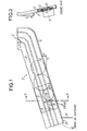
- the device for accumulating and collecting coins with ejection comprises, at its inlet E, a slot 1 for introducing coins 2 and, following this slot 1, a slide 3 formed by two parallel cheeks 5 and 6 and a rolling track 4 descending and inclined at an acute angle a of the order of 20 to 30 ° relative to a horizontal plane H.
- the cheeks 5 and 6 of the slide 3 are themselves inclined at an acute angle fJ (FIG. 2) of the order of 5 to 7 ° relative to a vertical plane V, which causes the pieces 2 to rest against one of the cheeks , called rear cheek 5, along which are arranged sliding heels 7 intended to promote the sliding of the parts 2.
- This inclination of an angle f J therefore makes it possible to remove part of the other cheek 6, called front cheek , in the lower part of the slide 3, to arrange a window 8 there.
- An electromagnet 9 (FIG. 2) with a plunger core 10 is mounted on the rear cheek 5 outside the slideway 3, on the part of this rear cheek 5 opposite the window 8.
- the plunger core 10 is oriented perpendicularly to the cheeks 5 and 6 and its front end can pass through an orifice 11 formed in the rear cheek 5.
- This plunger core 10 constitutes a retractable stop for the parts 2.
- Two light barriers 12 and 13 are arranged upstream and downstream of the stop 10, in the vicinity thereof, for detecting the passage of the parts 2.
- the dispensing device of which the device according to the invention forms part, further comprises control means of the type known in the prior art and not shown in FIGS. 1 and 2.
- the electromagnet 9 and the light barriers 12 and 13 are electrically connected to them.
- These control means control the electromagnet 9. They can also provide accounting (that is to say, for example in the case of a telephone set, the comparison of the flow rate resulting from charging pulses pro from the telephone exchange and the credit represented by the coins already cashed).
- coins validation bodies (not shown in Figures 1 and 2) are incorporated into the dispensing device.
- the lower part 15 of the slide 3 emerges from a partition 14 towards the inside of the dispensing device so that the pieces 2 to be returned to the users of said device fall into a restoring bowl (not shown), and the pieces 2 ejected, as explained below, through window 8, reach the body (not shown) of the device.
- the electromagnet 9 In the case of a return of all the coins 2 remaining in the slide 3, the electromagnet 9 is excited, the stop 10 retracts and the coins 2 roll towards the return bowl. When the first barrier 12 is no longer obscured, the electromagnet 9 is de-energized and the stop 10 returns to the extended position: the dispensing device is again ready to serve.
- the collection process takes place in the manner indicated above for the coin (s) to be collected then the electromagnet 9 remains excited (in other words, the stop, 10 remains retracted) to allow the coins 2 remaining in the slide 3 to roll until the exit of the latter- towards the bowl of restitution.
- the electromagnet 9 is de-energized and the stop 10 returns to the extended position.
- the accumulator-collector device can obviously accept coins of the same predetermined type.
- the dispensing apparatus of which this device is a part can then comprise "in parallel" as many such devices as there are types of coins to be received.
- the device which is the subject of the invention can also accumulate and collect coins of different types arriving in bulk on the slide, provided that the dimensions of this device are adapted (length and width of the coin insertion slot, width of the raceway, height of cheeks of the slide, position of the retractable stop and dimensions of said window) to those of the various parts to be received. Furthermore, the dispensing apparatus of which the device according to the invention forms part must then further comprise means of identifying and accounting for these pieces of different types, placed before the cash register of the dispensing apparatus.
- the fource required to eject a moving part in the slide is low (less than 50 gf), which allows the use of a reduced size electromagnet (occupying a volume of 2 to 3 c m3) .
- the accumulator collecting device that is the subject of the invention is simple to produce and does not require any precise adjustment, all the active elements (stop, possible light barriers) operating in all or nothing. Its dimensions are small and it is very easy to mount in a product or service distributor. Its simplicity makes it a device with good operating safety and inexpensive.
Landscapes
- Physics & Mathematics (AREA)
- General Physics & Mathematics (AREA)
- Control Of Vending Devices And Auxiliary Devices For Vending Devices (AREA)
Applications Claiming Priority (2)
| Application Number | Priority Date | Filing Date | Title |
|---|---|---|---|
| FR8023840A FR2494011A1 (fr) | 1980-11-07 | 1980-11-07 | Dispositif accumulateur-encaisseur de pie ces de monnaie a ejection |
| FR8023840 | 1980-11-07 |
Publications (2)
| Publication Number | Publication Date |
|---|---|
| EP0052043A1 EP0052043A1 (fr) | 1982-05-19 |
| EP0052043B1 true EP0052043B1 (fr) | 1985-08-21 |
Family
ID=9247792
Family Applications (1)
| Application Number | Title | Priority Date | Filing Date |
|---|---|---|---|
| EP19810401694 Expired EP0052043B1 (fr) | 1980-11-07 | 1981-10-26 | Dispositif accumulateur-encaisseur de pièces de monnaie à éjection |
Country Status (4)
| Country | Link |
|---|---|
| EP (1) | EP0052043B1 (enExample) |
| DE (1) | DE3171936D1 (enExample) |
| DK (1) | DK149289C (enExample) |
| FR (1) | FR2494011A1 (enExample) |
Families Citing this family (8)
| Publication number | Priority date | Publication date | Assignee | Title |
|---|---|---|---|---|
| JPH049656Y2 (enExample) * | 1986-12-01 | 1992-03-10 | ||
| ES2021228A6 (es) * | 1990-03-09 | 1991-10-16 | Alcatel Citesa | Dispositivo monocanal de control, almacenaje y cobro de monedas. |
| ES1015132Y (es) * | 1990-09-05 | 1992-01-01 | Azkoyen Industrial, S.A. | Carcasa para selectores de monedas. |
| DE4202559C2 (de) * | 1992-01-30 | 1996-09-12 | Nat Rejectors Gmbh | Münzprüfer |
| FR2755275B1 (fr) * | 1996-10-24 | 1999-01-08 | Soc D Mecanique Et De Plastiqu | Dispositif d'encaissement ou de rejet de pieces de monnaie ou de jetons circulaires, et son procede de mise en oeuvre |
| DE59708206D1 (de) * | 1997-12-05 | 2002-10-17 | Ascom Autelca Ag Guemligen | Vorrichtung und Anordnung zum Speichern von Münzen mit deren Zwischenspeicherung |
| US7310544B2 (en) | 2004-07-13 | 2007-12-18 | Dexcom, Inc. | Methods and systems for inserting a transcutaneous analyte sensor |
| CN110615211A (zh) * | 2019-09-28 | 2019-12-27 | 深圳智加问道科技有限公司 | 一种手机回收终端 |
Family Cites Families (6)
| Publication number | Priority date | Publication date | Assignee | Title |
|---|---|---|---|---|
| DK122198B (da) * | 1970-07-06 | 1972-01-31 | Gnt Automatic As | Møntindkasseringsmekanisme til mønttelefonautomat. |
| DE2055133A1 (de) * | 1970-11-10 | 1972-05-18 | Pruemm G | Elektronischer Münzprüfer |
| DE2116234C3 (de) * | 1971-04-02 | 1974-11-07 | Standard Elektrik Lorenz Ag, 7000 Stuttgart | Münzkanal |
| US3941226A (en) * | 1974-03-22 | 1976-03-02 | The Wurlitzer Company | Electronic coin switch |
| DE2906963A1 (de) * | 1979-02-22 | 1980-09-04 | Siemens Ag | Muenzkassier- und rueckgabeeinrichtung fuer muenzautomaten |
| DE2908403C2 (de) * | 1979-03-03 | 1986-04-17 | Standard Elektrik Lorenz Ag, 7000 Stuttgart | Kassiereinrichtung |
-
1980
- 1980-11-07 FR FR8023840A patent/FR2494011A1/fr active Granted
-
1981
- 1981-10-26 EP EP19810401694 patent/EP0052043B1/fr not_active Expired
- 1981-10-26 DE DE8181401694T patent/DE3171936D1/de not_active Expired
- 1981-10-30 DK DK481481A patent/DK149289C/da active
Also Published As
| Publication number | Publication date |
|---|---|
| DK149289B (da) | 1986-04-21 |
| EP0052043A1 (fr) | 1982-05-19 |
| FR2494011B1 (enExample) | 1984-03-16 |
| FR2494011A1 (fr) | 1982-05-14 |
| DK149289C (da) | 1986-09-29 |
| DE3171936D1 (en) | 1985-09-26 |
| DK481481A (da) | 1982-05-08 |
Similar Documents
| Publication | Publication Date | Title |
|---|---|---|
| EP0587883B1 (fr) | Dispositif pour la separation des pieces, jetons et analogues et appareils de paiement automatique | |
| EP0609923B1 (fr) | Dispositif pour vérifier la conformité et diriger des objets introduits dans un distributeur | |
| EP0052043B1 (fr) | Dispositif accumulateur-encaisseur de pièces de monnaie à éjection | |
| EP0351295B1 (fr) | Dispositif de traitement de pièces de monnaie | |
| EP0627712B1 (fr) | Dispositif pour trier et stocker des objets introduits à titre de paiement dans un distributeur | |
| EP1340202A1 (fr) | Appareil securise a pieces de monnaie | |
| FR2678595A1 (fr) | Machine de reception et de distribution de billets. | |
| FR2605614A1 (fr) | Distributeur de billets de banque d'une machine destinee a recevoir et distribuer des billets | |
| CH654128A5 (fr) | Dispositif pour encourager la restitution de chariots a roulettes a une aire de stockage. | |
| EP0025754B1 (fr) | Procédé et installation pour encourager la restitution d'un véhicule roulant, tel qu'un chariot de supermarché | |
| CA2352129A1 (fr) | Faconneuse de patons | |
| EP0233232B1 (fr) | Dispositif de distribution et de vente de supports souples | |
| FR2880008A1 (fr) | Dispositif de mise a disposition d'un ticket imprime | |
| FR2605995A1 (fr) | Dispositif de compression des billets de banque pour une machine de reception et de distribution de billets de banque | |
| EP0816267B1 (fr) | Dispositif d'éjection d'articles empilés dans un magasin et système de distribution automatique d'articles de magasins comprenant chacun un dispositif d'éjection d'articles du magasin | |
| EP1107925B1 (fr) | Distributeur automatique d'objet par gravite sur des glissieres | |
| FR2698028A1 (fr) | Machine à écraser des boîtes métalliques, notamment des boîtes de boisson cylindriques. | |
| EP0668574A1 (fr) | Dispositif de délivrance de titre pour une machine d'élaboration et de délivrance de titre | |
| EP0102674B1 (fr) | Distributeur à prépayement | |
| FR3093446A1 (fr) | Automate de reconnaissance et de compactage de déchets | |
| FR2713103A3 (fr) | Table à jouer, conduit à balles et mécanisme de libération de balles. | |
| FR2659467A1 (fr) | Collecteur de pieces de monnaie. | |
| CH656668A5 (en) | Automatic dispenser, in particular for banks | |
| FR2796186A1 (fr) | Distributeur de cartes rigides ou relativement rigides | |
| BE663729A (enExample) |
Legal Events
| Date | Code | Title | Description |
|---|---|---|---|
| PUAI | Public reference made under article 153(3) epc to a published international application that has entered the european phase |
Free format text: ORIGINAL CODE: 0009012 |
|
| AK | Designated contracting states |
Designated state(s): CH DE GB SE |
|
| 17P | Request for examination filed |
Effective date: 19821023 |
|
| GRAA | (expected) grant |
Free format text: ORIGINAL CODE: 0009210 |
|
| AK | Designated contracting states |
Designated state(s): CH DE GB LI SE |
|
| REF | Corresponds to: |
Ref document number: 3171936 Country of ref document: DE Date of ref document: 19850926 |
|
| PLBE | No opposition filed within time limit |
Free format text: ORIGINAL CODE: 0009261 |
|
| STAA | Information on the status of an ep patent application or granted ep patent |
Free format text: STATUS: NO OPPOSITION FILED WITHIN TIME LIMIT |
|
| 26N | No opposition filed | ||
| PG25 | Lapsed in a contracting state [announced via postgrant information from national office to epo] |
Ref country code: SE Effective date: 19871027 |
|
| PG25 | Lapsed in a contracting state [announced via postgrant information from national office to epo] |
Ref country code: LI Effective date: 19871031 Ref country code: CH Effective date: 19871031 |
|
| GBPC | Gb: european patent ceased through non-payment of renewal fee | ||
| REG | Reference to a national code |
Ref country code: CH Ref legal event code: PL |
|
| PG25 | Lapsed in a contracting state [announced via postgrant information from national office to epo] |
Ref country code: DE Effective date: 19880701 |
|
| PG25 | Lapsed in a contracting state [announced via postgrant information from national office to epo] |
Ref country code: GB Effective date: 19881118 |
|
| EUG | Se: european patent has lapsed |
Ref document number: 81401694.5 Effective date: 19880707 |