EP0052026B1 - Dispositif de starter automatique pour carburateur double corps - Google Patents
Dispositif de starter automatique pour carburateur double corps Download PDFInfo
- Publication number
- EP0052026B1 EP0052026B1 EP81401579A EP81401579A EP0052026B1 EP 0052026 B1 EP0052026 B1 EP 0052026B1 EP 81401579 A EP81401579 A EP 81401579A EP 81401579 A EP81401579 A EP 81401579A EP 0052026 B1 EP0052026 B1 EP 0052026B1
- Authority
- EP
- European Patent Office
- Prior art keywords
- arrangement
- lever
- flaps
- controlling
- engine
- Prior art date
- Legal status (The legal status is an assumption and is not a legal conclusion. Google has not performed a legal analysis and makes no representation as to the accuracy of the status listed.)
- Expired
Links
Images


Classifications
-
- F—MECHANICAL ENGINEERING; LIGHTING; HEATING; WEAPONS; BLASTING
- F02—COMBUSTION ENGINES; HOT-GAS OR COMBUSTION-PRODUCT ENGINE PLANTS
- F02M—SUPPLYING COMBUSTION ENGINES IN GENERAL WITH COMBUSTIBLE MIXTURES OR CONSTITUENTS THEREOF
- F02M1/00—Carburettors with means for facilitating engine's starting or its idling below operational temperatures
- F02M1/08—Carburettors with means for facilitating engine's starting or its idling below operational temperatures the means to facilitate starting or idling becoming operative or inoperative automatically
- F02M1/10—Carburettors with means for facilitating engine's starting or its idling below operational temperatures the means to facilitate starting or idling becoming operative or inoperative automatically dependent on engine temperature, e.g. having thermostat
-
- F—MECHANICAL ENGINEERING; LIGHTING; HEATING; WEAPONS; BLASTING
- F02—COMBUSTION ENGINES; HOT-GAS OR COMBUSTION-PRODUCT ENGINE PLANTS
- F02M—SUPPLYING COMBUSTION ENGINES IN GENERAL WITH COMBUSTIBLE MIXTURES OR CONSTITUENTS THEREOF
- F02M11/00—Multi-stage carburettors, Register-type carburettors, i.e. with slidable or rotatable throttling valves in which a plurality of fuel nozzles, other than only an idling nozzle and a main one, are sequentially exposed to air stream by throttling valve
- F02M11/02—Multi-stage carburettors, Register-type carburettors, i.e. with slidable or rotatable throttling valves in which a plurality of fuel nozzles, other than only an idling nozzle and a main one, are sequentially exposed to air stream by throttling valve with throttling valve, e.g. of flap or butterfly type, in a later stage opening automatically
Definitions
- the present invention is in the field of carburetors for internal combustion engines, and more specifically relates to an automatic choke device intended to be incorporated into a double-barrel carburetor.
- Bimetal type automatic starters currently mounted on the carburetors are intended to perform two functions at the same time, namely to supply the engine at the start to ensure a given speed when empty and on the other hand to allow starting. when the vehicle is cold, until a given engine temperature is obtained, for example of the order of 80 ° C.
- These two functions being ensured by a single mechanism, it is very difficult to obtain a good adaptation of the richness of the mixture for running in transient regime, this richness being too important in stabilized regime and in idle mode, which translates by a diet that is too important when stopped.
- the automatic choke device for carburetor according to the present invention is of the aforementioned type and is characterized in that this arrangement for controlling the flaps of the carburetor bodies cooperates with this arrangement for controlling the throttle valve of the second carburetor body by the same pressure applied to the two pneumatic members of these respective arrangements of control from the intake manifold.
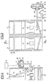
- the carburetor on which is mounted the automatic choke device according to the present invention consists of two bodies A and B, the mechanical control of the butterflies, which is not the subject of the invention, not being shown in the drawing.
- the automatic choke device according to the invention consists of two arrangements, one of which is mounted on the first carburetor body A and the other on the second body B.
- the arrangement mounted on the body A is more precisely designed to adjust the opening of the flaps 3, 4.
- This arrangement consists of a rotary lever 1, the position of which is controlled by a heat-sensitive element, of the bimetallic strip type 2, the movement of which is set according to the engine temperature.
- the lever 1 is connected to the axis 23 of the flaps 3 and 4 by a tie rod 5, itself articulated to a control rod 5a secured to said axis 23.
- the lever 1 is directly connected to the lower end, provided with a notch 7, a rod 6 which, by its opposite end, is secured to the membrane 8 of a pressure capsule 9, comprising in its upper compartment a spring 10 intended to exert a given force on the membrane 8
- Adjustment means in the form of a stop 11 are mounted in the pressure capsule 9, the upper compartment of which communicates with the intake manifold by a flexible conduit, pressure delay means, for example in the form of 'A regulator housing 12, being disposed between the pressure capsule 9 and the intake manifold.
- the second arrangement installed on the second body B of the carburettor aims to provide a volume of air necessary for starting the engine and for making it run empty by acting on the throttle valve.
- This arrangement comprises a cam 13 whose angular position is controlled by a thermosensitive element 14 whose movement is regulated as a function of the temperature of the engine.
- This cam 13 is intended to limit the complete closure of the throttle valve 25 of the second body B of the carburetor by means of a push rod 16, articulated by one of its ends to a lever 15 secured to the throttle shaft 25.
- a lever 17 at the end of which is provided an adjustable stop 18 intended to come into contact with the cam 13.
- the other end of the push rod 16 is connected to the membrane 19 d '' a pressure capsule 20 whose compartment on the side of the rod 16 is subjected to atmospheric pressure while the other compartment, in which is mounted a spring 21 intended to apply a force on the membrane 19 and to control the opening of the butterfly 25, communicates by a nozzle 22 and a flexible conduit with the intake manifold.
- a nozzle 22 In the part of the housing subjected to atmospheric pressure is disposed an adjustment stop 28.
- the diffusers 26 and 24 are shown in the carburetor bodies A and B respectively.
- the automatic choke device operates in the following manner: Before actuating the engine with the starter, the position of the constituent elements of the choke is shown in FIGS. 1 and 2.
- the spring 21 by means of the rod 16 pushes the lever 15 and causes a certain opening of the butterfly 25 of the second body B.
- the value of this opening is given by the adjustable stop 28. This value is established during setting point of the choke device.
- the bimetallic strip 2 On the first body, the bimetallic strip 2, by means of the lever 1 and the tie rod 5, turns the axis of the flap 23 and closes the flaps of the first and second bodies 3 and 4.
- the membrane 8 compresses the spring 10 and the rod 6 rotates the lever 1 which, consequently, opens the flaps 3 and 4. This position of the system is shown in FIGS. 3 and 4.
- the engine is supplied with fuel in this position by the idle circuits of the first and second bodies. These circuits are not shown in the drawings. If the quantity of fuel is not sufficient, it can be increased by changing the idle jet of the second body, without causing the increase in consumption in hot running.
- FIGS 5 and 6 are shown the components of the automatic choke at the time of acceleration.
- the butterfly 27 of the first body A or also of the second body B is opened if the acceleration is strong.
- the engine vacuum drops quickly.
- the vacuum in the upper part of the housing 9 decreases as quickly because the delay housing 12 does not work in this direction.
- the res fate 10 pushes back the rod 6, the bimetallic strip 2 turns the lever 1 and the drawing 5 closes the flaps 3 and 4.
- the vacuum under the flap of the first body increases rapidly, which causes a strong fuel flow, through the diffuser 26. Once the vehicle speed has stabilized, the engine vacuum increases and the flaps 3 and 4 are in the open position presented on board 23.
- the second body B with its own constituent elements is not shown in FIGS. 5 and 6, because in this operating phase the second body does not play any role.
- the bimetallic strip 2 maintains the flaps 3 and 4 in the open position and the bimetallic strip 14 turns the cam 13. Consequently, the rod 16 takes a position such that the butterfly valve 25 of the second body B is completely closed. To obtain this position, it is necessary to act on the setting of the spring 21 and of the return spring of the second body.
- the system on the second body opens the butterfly 25 of the second body B.
- the depression of the engine withdraws the rod 16 via the membrane 19 and the butterfly 25 of the second body B is closed. Idling is ensured by the fixed position of the butterfly 27 of the first body A.
Landscapes
- Engineering & Computer Science (AREA)
- Chemical & Material Sciences (AREA)
- Combustion & Propulsion (AREA)
- Mechanical Engineering (AREA)
- General Engineering & Computer Science (AREA)
- Means For Warming Up And Starting Carburetors (AREA)
- Control Of Throttle Valves Provided In The Intake System Or In The Exhaust System (AREA)
Applications Claiming Priority (2)
| Application Number | Priority Date | Filing Date | Title |
|---|---|---|---|
| FR8023851A FR2493921A1 (fr) | 1980-11-07 | 1980-11-07 | Dispositif de starter automatique pour carburateur double corps |
| FR8023851 | 1980-11-07 |
Publications (2)
| Publication Number | Publication Date |
|---|---|
| EP0052026A1 EP0052026A1 (fr) | 1982-05-19 |
| EP0052026B1 true EP0052026B1 (fr) | 1986-01-29 |
Family
ID=9247799
Family Applications (1)
| Application Number | Title | Priority Date | Filing Date |
|---|---|---|---|
| EP81401579A Expired EP0052026B1 (fr) | 1980-11-07 | 1981-10-13 | Dispositif de starter automatique pour carburateur double corps |
Country Status (8)
| Country | Link |
|---|---|
| US (1) | US4385009A (oth) |
| EP (1) | EP0052026B1 (oth) |
| JP (1) | JPS57108445A (oth) |
| DE (1) | DE3173645D1 (oth) |
| ES (1) | ES8300177A1 (oth) |
| FR (1) | FR2493921A1 (oth) |
| MX (1) | MX154725A (oth) |
| PT (1) | PT73938B (oth) |
Families Citing this family (1)
| Publication number | Priority date | Publication date | Assignee | Title |
|---|---|---|---|---|
| FR2537212A1 (fr) * | 1982-12-07 | 1984-06-08 | Renault | Dispositif de starter automatique pour carburateurs |
Citations (1)
| Publication number | Priority date | Publication date | Assignee | Title |
|---|---|---|---|---|
| DE2633546A1 (de) * | 1976-05-31 | 1977-12-15 | Sibe | Vergaser mit hilfsstartvorrichtung |
Family Cites Families (13)
| Publication number | Priority date | Publication date | Assignee | Title |
|---|---|---|---|---|
| US2609806A (en) * | 1950-03-07 | 1952-09-09 | Bendix Aviat Corp | Carburetor |
| GB842079A (en) | 1958-05-23 | 1960-07-20 | Gen Motors Corp | Improved apparatus for forming the combustible charge for internal combustion engines |
| FR1291578A (fr) | 1961-02-20 | 1962-04-27 | Sibe | Perfectionnements apportés aux carburateurs munis d'un dispositif auxiliaire de départ à commande automatique |
| US3294374A (en) * | 1964-09-29 | 1966-12-27 | Acf Ind Inc | Carburetor |
| US3785624A (en) * | 1970-10-12 | 1974-01-15 | Ethyl Corp | Carburetor |
| FR2248418B2 (oth) * | 1973-10-19 | 1980-11-07 | Sibe | |
| US3831567A (en) * | 1973-08-16 | 1974-08-27 | Ford Motor Co | Supplemental pulldown mechanism for carburetor automatic choke |
| US3965223A (en) * | 1974-09-18 | 1976-06-22 | Schmelzer Corporation | Charge forming device |
| DE2446403A1 (de) * | 1974-09-28 | 1976-04-08 | Daimler Benz Ag | Einrichtung zur drehzahlstabilisierung im leerlauf nach dem starten bei einem vergaser fuer ottomotoren |
| JPS5154133A (en) * | 1974-11-06 | 1976-05-13 | Honda Motor Co Ltd | Kikakino chookubenseigyosochi |
| US3947531A (en) * | 1974-12-23 | 1976-03-30 | Ford Motor Company | Carburetor with controlled fast idle cam |
| JPS5823499B2 (ja) | 1975-11-14 | 1983-05-16 | トヨタ自動車株式会社 | ナイネンキカン |
| US4053542A (en) * | 1976-07-22 | 1977-10-11 | Acf Industries, Inc. | Control means for secondary throttle |
-
1980
- 1980-11-07 FR FR8023851A patent/FR2493921A1/fr active Granted
-
1981
- 1981-10-13 DE DE8181401579T patent/DE3173645D1/de not_active Expired
- 1981-10-13 EP EP81401579A patent/EP0052026B1/fr not_active Expired
- 1981-10-20 US US06/316,449 patent/US4385009A/en not_active Expired - Fee Related
- 1981-11-06 MX MX190004A patent/MX154725A/es unknown
- 1981-11-06 PT PT73938A patent/PT73938B/pt unknown
- 1981-11-06 ES ES506922A patent/ES8300177A1/es not_active Expired
- 1981-11-06 JP JP56178240A patent/JPS57108445A/ja active Pending
Patent Citations (1)
| Publication number | Priority date | Publication date | Assignee | Title |
|---|---|---|---|---|
| DE2633546A1 (de) * | 1976-05-31 | 1977-12-15 | Sibe | Vergaser mit hilfsstartvorrichtung |
Also Published As
| Publication number | Publication date |
|---|---|
| MX154725A (es) | 1987-12-07 |
| FR2493921B1 (oth) | 1984-04-20 |
| PT73938B (fr) | 1983-04-29 |
| EP0052026A1 (fr) | 1982-05-19 |
| FR2493921A1 (fr) | 1982-05-14 |
| US4385009A (en) | 1983-05-24 |
| ES506922A0 (es) | 1982-10-01 |
| DE3173645D1 (en) | 1986-03-13 |
| PT73938A (fr) | 1981-12-01 |
| ES8300177A1 (es) | 1982-10-01 |
| JPS57108445A (en) | 1982-07-06 |
Similar Documents
| Publication | Publication Date | Title |
|---|---|---|
| FR2568631A1 (fr) | Carburateur a dispositif de depart automatique | |
| EP0079255B1 (fr) | Dispositif perfectionné de commande de la pression de suralimentation d'un moteur turbocompressé permettant d'améliorer la réponse dynamique | |
| FR2541723A1 (fr) | Groupe motopropulseur pour un avion | |
| EP0052026B1 (fr) | Dispositif de starter automatique pour carburateur double corps | |
| FR2601720A1 (fr) | Procede et dispositif pour commander, en fonction de la charge, le distributeur de la turbine du turbo-compresseur d'un moteur a combustion interne | |
| EP0053376B1 (fr) | Dispositif de suralimentation de moteur à combustion interne par turbocompresseur | |
| FR2501293A1 (fr) | Procede d'alimentation en melange air-essence d'un moteur a combustion interne et carburateur pour sa mise en oeuvre | |
| FR2504981A1 (fr) | Procede et dispositif d'alimentation en melange air-carburant d'un moteur a combustion interne a deux groupes de cylindres, dans lequel le debit de melange fourni au deuxieme groupe de cylindres durant la phase de montee en temperature est constant | |
| EP0113268B1 (fr) | Dispositif de starter automatique pour carburateurs | |
| EP0080911B1 (fr) | Dispositif de commande pneumatique de la pression de suralimentation d'un moteur turbocompressé | |
| EP0074905A1 (fr) | Dispositif de suralimentation d'un moteur à combustion interne | |
| FR2503262A1 (fr) | Installation pour regler la vitesse de rotation de ralenti d'un moteur a combustion interne | |
| FR2569229A1 (fr) | Installation d'injection de carburant pour moteurs diesel, en particulier pour moteurs diesel pour vehicules | |
| EP0156670B1 (fr) | Dispositif de carburation pour moteur | |
| EP0088678B1 (fr) | Dispositif de commande pneumatique du volet d'air d'un carburateur pour moteur à combustion interne | |
| EP0029385A1 (fr) | Dispositif de régulation de débit de carburant pour moteur suralimenté | |
| FR2507686A1 (fr) | Procede de commande de recyclage du gaz d'echappement pour moteurs a combustion interne | |
| FR2560290A1 (fr) | Moteur a combustion interne multicylindres | |
| FR2509378A1 (fr) | Carburateur avec commande automatique du volet de depart a froid | |
| EP0180522B1 (fr) | Dispositif de carburation comportant des moyens de coupure en décélération | |
| EP0029789A1 (fr) | Carburateurs comportant un dispositif auxiliaire de départ | |
| BE555126A (oth) | ||
| FR2667356A1 (fr) | Dispositif pour commander un papillon d'une soupape de regulation d'un moteur a turbocompresseur a gaz d'echappement. | |
| BE386259A (oth) | ||
| FR2529256A1 (fr) | Dispositif d'alimentation pour moteur, a coupure en deceleration |
Legal Events
| Date | Code | Title | Description |
|---|---|---|---|
| PUAI | Public reference made under article 153(3) epc to a published international application that has entered the european phase |
Free format text: ORIGINAL CODE: 0009012 |
|
| 17P | Request for examination filed |
Effective date: 19811016 |
|
| AK | Designated contracting states |
Designated state(s): BE DE GB IT NL SE |
|
| GRAA | (expected) grant |
Free format text: ORIGINAL CODE: 0009210 |
|
| AK | Designated contracting states |
Designated state(s): BE DE GB IT NL SE |
|
| ITF | It: translation for a ep patent filed | ||
| REF | Corresponds to: |
Ref document number: 3173645 Country of ref document: DE Date of ref document: 19860313 |
|
| PLBE | No opposition filed within time limit |
Free format text: ORIGINAL CODE: 0009261 |
|
| STAA | Information on the status of an ep patent application or granted ep patent |
Free format text: STATUS: NO OPPOSITION FILED WITHIN TIME LIMIT |
|
| 26N | No opposition filed | ||
| PGFP | Annual fee paid to national office [announced via postgrant information from national office to epo] |
Ref country code: SE Payment date: 19890918 Year of fee payment: 9 |
|
| PGFP | Annual fee paid to national office [announced via postgrant information from national office to epo] |
Ref country code: BE Payment date: 19890919 Year of fee payment: 9 |
|
| PGFP | Annual fee paid to national office [announced via postgrant information from national office to epo] |
Ref country code: DE Payment date: 19890922 Year of fee payment: 9 |
|
| PGFP | Annual fee paid to national office [announced via postgrant information from national office to epo] |
Ref country code: GB Payment date: 19890930 Year of fee payment: 9 |
|
| ITTA | It: last paid annual fee | ||
| PGFP | Annual fee paid to national office [announced via postgrant information from national office to epo] |
Ref country code: NL Payment date: 19891031 Year of fee payment: 9 |
|
| PG25 | Lapsed in a contracting state [announced via postgrant information from national office to epo] |
Ref country code: GB Effective date: 19901013 |
|
| PG25 | Lapsed in a contracting state [announced via postgrant information from national office to epo] |
Ref country code: SE Effective date: 19901014 |
|
| PG25 | Lapsed in a contracting state [announced via postgrant information from national office to epo] |
Ref country code: BE Effective date: 19901031 |
|
| BERE | Be: lapsed |
Owner name: REGIE NATIONALE DES USINES RENAULT Effective date: 19901031 |
|
| PG25 | Lapsed in a contracting state [announced via postgrant information from national office to epo] |
Ref country code: NL Effective date: 19910501 |
|
| GBPC | Gb: european patent ceased through non-payment of renewal fee | ||
| NLV4 | Nl: lapsed or anulled due to non-payment of the annual fee | ||
| PG25 | Lapsed in a contracting state [announced via postgrant information from national office to epo] |
Ref country code: DE Effective date: 19910702 |
|
| EUG | Se: european patent has lapsed |
Ref document number: 81401579.8 Effective date: 19910603 |