EP0052000B1 - Variable colour filters - Google Patents
Variable colour filters Download PDFInfo
- Publication number
- EP0052000B1 EP0052000B1 EP81305300A EP81305300A EP0052000B1 EP 0052000 B1 EP0052000 B1 EP 0052000B1 EP 81305300 A EP81305300 A EP 81305300A EP 81305300 A EP81305300 A EP 81305300A EP 0052000 B1 EP0052000 B1 EP 0052000B1
- Authority
- EP
- European Patent Office
- Prior art keywords
- polariser
- filter
- plane
- light
- liquid crystal
- Prior art date
- Legal status (The legal status is an assumption and is not a legal conclusion. Google has not performed a legal analysis and makes no representation as to the accuracy of the status listed.)
- Expired
Links
- 239000004973 liquid crystal related substance Substances 0.000 claims description 39
- 230000005540 biological transmission Effects 0.000 claims description 26
- 230000003287 optical effect Effects 0.000 claims description 20
- 239000003086 colorant Substances 0.000 claims description 15
- 238000001429 visible spectrum Methods 0.000 claims description 15
- 230000003595 spectral effect Effects 0.000 claims description 12
- 239000004988 Nematic liquid crystal Substances 0.000 claims description 11
- 239000000203 mixture Substances 0.000 claims description 6
- 239000013078 crystal Substances 0.000 claims description 5
- 238000001228 spectrum Methods 0.000 claims description 5
- 239000000975 dye Substances 0.000 description 52
- 210000002858 crystal cell Anatomy 0.000 description 29
- 210000004027 cell Anatomy 0.000 description 13
- 239000000463 material Substances 0.000 description 9
- AJDUTMFFZHIJEM-UHFFFAOYSA-N n-(9,10-dioxoanthracen-1-yl)-4-[4-[[4-[4-[(9,10-dioxoanthracen-1-yl)carbamoyl]phenyl]phenyl]diazenyl]phenyl]benzamide Chemical compound O=C1C2=CC=CC=C2C(=O)C2=C1C=CC=C2NC(=O)C(C=C1)=CC=C1C(C=C1)=CC=C1N=NC(C=C1)=CC=C1C(C=C1)=CC=C1C(=O)NC1=CC=CC2=C1C(=O)C1=CC=CC=C1C2=O AJDUTMFFZHIJEM-UHFFFAOYSA-N 0.000 description 9
- 239000001043 yellow dye Substances 0.000 description 9
- 238000000576 coating method Methods 0.000 description 5
- 239000011521 glass Substances 0.000 description 5
- LFVGISIMTYGQHF-UHFFFAOYSA-N ammonium dihydrogen phosphate Chemical compound [NH4+].OP(O)([O-])=O LFVGISIMTYGQHF-UHFFFAOYSA-N 0.000 description 4
- 229910000387 ammonium dihydrogen phosphate Inorganic materials 0.000 description 4
- 235000019837 monoammonium phosphate Nutrition 0.000 description 4
- 238000010521 absorption reaction Methods 0.000 description 3
- 230000000694 effects Effects 0.000 description 3
- 230000005855 radiation Effects 0.000 description 3
- 235000019796 monopotassium phosphate Nutrition 0.000 description 2
- 239000000126 substance Substances 0.000 description 2
- PLXMOAALOJOTIY-FPTXNFDTSA-N Aesculin Natural products OC[C@@H]1[C@@H](O)[C@H](O)[C@@H](O)[C@H](O)[C@H]1Oc2cc3C=CC(=O)Oc3cc2O PLXMOAALOJOTIY-FPTXNFDTSA-N 0.000 description 1
- 108010010803 Gelatin Proteins 0.000 description 1
- 239000004372 Polyvinyl alcohol Substances 0.000 description 1
- 230000015572 biosynthetic process Effects 0.000 description 1
- 239000011248 coating agent Substances 0.000 description 1
- 239000002131 composite material Substances 0.000 description 1
- 238000009792 diffusion process Methods 0.000 description 1
- 230000005684 electric field Effects 0.000 description 1
- 230000005670 electromagnetic radiation Effects 0.000 description 1
- 229920000159 gelatin Polymers 0.000 description 1
- 239000008273 gelatin Substances 0.000 description 1
- 235000019322 gelatine Nutrition 0.000 description 1
- 235000011852 gelatine desserts Nutrition 0.000 description 1
- 239000007788 liquid Substances 0.000 description 1
- 230000004048 modification Effects 0.000 description 1
- 238000012986 modification Methods 0.000 description 1
- 229910000402 monopotassium phosphate Inorganic materials 0.000 description 1
- PJNZPQUBCPKICU-UHFFFAOYSA-N phosphoric acid;potassium Chemical compound [K].OP(O)(O)=O PJNZPQUBCPKICU-UHFFFAOYSA-N 0.000 description 1
- 229920003023 plastic Polymers 0.000 description 1
- 229920002451 polyvinyl alcohol Polymers 0.000 description 1
- 238000003786 synthesis reaction Methods 0.000 description 1
Images
Classifications
-
- G—PHYSICS
- G02—OPTICS
- G02F—OPTICAL DEVICES OR ARRANGEMENTS FOR THE CONTROL OF LIGHT BY MODIFICATION OF THE OPTICAL PROPERTIES OF THE MEDIA OF THE ELEMENTS INVOLVED THEREIN; NON-LINEAR OPTICS; FREQUENCY-CHANGING OF LIGHT; OPTICAL LOGIC ELEMENTS; OPTICAL ANALOGUE/DIGITAL CONVERTERS
- G02F1/00—Devices or arrangements for the control of the intensity, colour, phase, polarisation or direction of light arriving from an independent light source, e.g. switching, gating or modulating; Non-linear optics
- G02F1/01—Devices or arrangements for the control of the intensity, colour, phase, polarisation or direction of light arriving from an independent light source, e.g. switching, gating or modulating; Non-linear optics for the control of the intensity, phase, polarisation or colour
- G02F1/13—Devices or arrangements for the control of the intensity, colour, phase, polarisation or direction of light arriving from an independent light source, e.g. switching, gating or modulating; Non-linear optics for the control of the intensity, phase, polarisation or colour based on liquid crystals, e.g. single liquid crystal display cells
- G02F1/133—Constructional arrangements; Operation of liquid crystal cells; Circuit arrangements
- G02F1/1333—Constructional arrangements; Manufacturing methods
- G02F1/1347—Arrangement of liquid crystal layers or cells in which the final condition of one light beam is achieved by the addition of the effects of two or more layers or cells
- G02F1/13471—Arrangement of liquid crystal layers or cells in which the final condition of one light beam is achieved by the addition of the effects of two or more layers or cells in which all the liquid crystal cells or layers remain transparent, e.g. FLC, ECB, DAP, HAN, TN, STN, SBE-LC cells
- G02F1/13473—Arrangement of liquid crystal layers or cells in which the final condition of one light beam is achieved by the addition of the effects of two or more layers or cells in which all the liquid crystal cells or layers remain transparent, e.g. FLC, ECB, DAP, HAN, TN, STN, SBE-LC cells for wavelength filtering or for colour display without the use of colour mosaic filters
-
- G—PHYSICS
- G02—OPTICS
- G02F—OPTICAL DEVICES OR ARRANGEMENTS FOR THE CONTROL OF LIGHT BY MODIFICATION OF THE OPTICAL PROPERTIES OF THE MEDIA OF THE ELEMENTS INVOLVED THEREIN; NON-LINEAR OPTICS; FREQUENCY-CHANGING OF LIGHT; OPTICAL LOGIC ELEMENTS; OPTICAL ANALOGUE/DIGITAL CONVERTERS
- G02F1/00—Devices or arrangements for the control of the intensity, colour, phase, polarisation or direction of light arriving from an independent light source, e.g. switching, gating or modulating; Non-linear optics
- G02F1/01—Devices or arrangements for the control of the intensity, colour, phase, polarisation or direction of light arriving from an independent light source, e.g. switching, gating or modulating; Non-linear optics for the control of the intensity, phase, polarisation or colour
- G02F1/03—Devices or arrangements for the control of the intensity, colour, phase, polarisation or direction of light arriving from an independent light source, e.g. switching, gating or modulating; Non-linear optics for the control of the intensity, phase, polarisation or colour based on ceramics or electro-optical crystals, e.g. exhibiting Pockels effect or Kerr effect
-
- G—PHYSICS
- G02—OPTICS
- G02F—OPTICAL DEVICES OR ARRANGEMENTS FOR THE CONTROL OF LIGHT BY MODIFICATION OF THE OPTICAL PROPERTIES OF THE MEDIA OF THE ELEMENTS INVOLVED THEREIN; NON-LINEAR OPTICS; FREQUENCY-CHANGING OF LIGHT; OPTICAL LOGIC ELEMENTS; OPTICAL ANALOGUE/DIGITAL CONVERTERS
- G02F1/00—Devices or arrangements for the control of the intensity, colour, phase, polarisation or direction of light arriving from an independent light source, e.g. switching, gating or modulating; Non-linear optics
- G02F1/01—Devices or arrangements for the control of the intensity, colour, phase, polarisation or direction of light arriving from an independent light source, e.g. switching, gating or modulating; Non-linear optics for the control of the intensity, phase, polarisation or colour
- G02F1/13—Devices or arrangements for the control of the intensity, colour, phase, polarisation or direction of light arriving from an independent light source, e.g. switching, gating or modulating; Non-linear optics for the control of the intensity, phase, polarisation or colour based on liquid crystals, e.g. single liquid crystal display cells
- G02F1/133—Constructional arrangements; Operation of liquid crystal cells; Circuit arrangements
- G02F1/1333—Constructional arrangements; Manufacturing methods
- G02F1/1335—Structural association of cells with optical devices, e.g. polarisers or reflectors
- G02F1/133528—Polarisers
- G02F1/133533—Colour selective polarisers
-
- G—PHYSICS
- G02—OPTICS
- G02F—OPTICAL DEVICES OR ARRANGEMENTS FOR THE CONTROL OF LIGHT BY MODIFICATION OF THE OPTICAL PROPERTIES OF THE MEDIA OF THE ELEMENTS INVOLVED THEREIN; NON-LINEAR OPTICS; FREQUENCY-CHANGING OF LIGHT; OPTICAL LOGIC ELEMENTS; OPTICAL ANALOGUE/DIGITAL CONVERTERS
- G02F1/00—Devices or arrangements for the control of the intensity, colour, phase, polarisation or direction of light arriving from an independent light source, e.g. switching, gating or modulating; Non-linear optics
- G02F1/01—Devices or arrangements for the control of the intensity, colour, phase, polarisation or direction of light arriving from an independent light source, e.g. switching, gating or modulating; Non-linear optics for the control of the intensity, phase, polarisation or colour
- G02F1/13—Devices or arrangements for the control of the intensity, colour, phase, polarisation or direction of light arriving from an independent light source, e.g. switching, gating or modulating; Non-linear optics for the control of the intensity, phase, polarisation or colour based on liquid crystals, e.g. single liquid crystal display cells
- G02F1/137—Devices or arrangements for the control of the intensity, colour, phase, polarisation or direction of light arriving from an independent light source, e.g. switching, gating or modulating; Non-linear optics for the control of the intensity, phase, polarisation or colour based on liquid crystals, e.g. single liquid crystal display cells characterised by the electro-optical or magneto-optical effect, e.g. field-induced phase transition, orientation effect, guest-host interaction or dynamic scattering
- G02F1/139—Devices or arrangements for the control of the intensity, colour, phase, polarisation or direction of light arriving from an independent light source, e.g. switching, gating or modulating; Non-linear optics for the control of the intensity, phase, polarisation or colour based on liquid crystals, e.g. single liquid crystal display cells characterised by the electro-optical or magneto-optical effect, e.g. field-induced phase transition, orientation effect, guest-host interaction or dynamic scattering based on orientation effects in which the liquid crystal remains transparent
- G02F1/1396—Devices or arrangements for the control of the intensity, colour, phase, polarisation or direction of light arriving from an independent light source, e.g. switching, gating or modulating; Non-linear optics for the control of the intensity, phase, polarisation or colour based on liquid crystals, e.g. single liquid crystal display cells characterised by the electro-optical or magneto-optical effect, e.g. field-induced phase transition, orientation effect, guest-host interaction or dynamic scattering based on orientation effects in which the liquid crystal remains transparent the liquid crystal being selectively controlled between a twisted state and a non-twisted state, e.g. TN-LC cell
Definitions
- Colour filters are well known in the photographic and optical arts and include devices and materials which deliberately change the spectral intensity distribution and/or state of polarisation of electromagnetic radiation incident upon them for purposes of synthesising colour.
- an absorption filter has chemical dyes dissolved in suitable media such as gelatin or plastic selectively to absorb or remove incident radiation of certain wavelengths, either partially or completely, such that the remaining radiation transmitted by the filter is of a desired colour.
- suitable media such as gelatin or plastic
- Other known filters make use of thin coatings or films of various substances to create interference effects to synthesize colour, and they are thus referred to as interference filters.
- Dichroic filters also are well known being those which selectively absorb radiation polarised in one direction more strongly than that polarised in other directions.
- ADP ammonium dihydrogen phosphate
- KDP potassium dihydrogen phosphate
- US Patent No. 2,493,200 discloses a colour filter corresponding to the precharacterising part of present claim 1. It combines a plurality of dichroic polarisers, a plane polariser, and a plurality of Kerr cells comprising ADP which are arranged to operate as fractional wave retardation plates.
- a mechanically operable variable colour filter comprising composite chromatic polarising components, an achromatic polarising filter, and a quarter-wave retardation plate is described in U.S. Patent No. 3,936,147.
- US-A-4019808 discloses a filter for varying the spectral composition of visible light comprising a plurality of optical elements stationed along the optical path of the light, including a plurality of colour selective dye polarising elements, and polarisation angle varying means.
- the dye polarising elements are pleochroic elements which comprise transparent crystals in which light viewed from different angles is seen in different colours.
- a diffusion plate is interposed between the viewer and the so-called polychrome display an observer has to be placed along the optical axis in order to be able to view the intended colour.
- This invention relates to novel filters for modifying the spectral composition of radiant energy.
- a filter according to the invention for varying the spectral composition comprises a plurality of optical elements including a plurality of different dichroic polarisers each of the dichroic polarisers being structured for selectively plane polarising a different part of the visible spectrum while transmitting the remainder of the visible spectrum unpolarised, at least one angle varying means associated with each of the dichroic polarisers for selectively varying the angle of the plane of polarisation of the linearly polarised light, and a plane polariser for polarising substantially uniformly all wavelengths of the visible spectrum stationed along the optical path of the light and is characterised in that the optical elements are arranged along the optical path in the following order: a magenta dichroic polariser, at least one angle varying means, the plane polariser, at least one angle varying means, a cyan dichroic polariser, at least one angle varying means, and a yellow dichroic polariser wherein the dichroic polarisers and the plane polariser are oriented with their
- the filter preferably being an electro-optical filter.
- the filter preferably being an electro-optical filter.
- each one of the dichroic polarising elements is responsible for one of the primary colours so that, depending on the state of energisation of any one of the angle varying means, any colour at all is visible regardless of the location of the observer.
- the filter of the invention comprises a plurality of differently coloured dye polarising elements stationed along an optical path to intercept light travelling therealong.
- Each dichroic polariser includes means for plane polarising part of the visible spectrum and for transmitting the remainder of the visible spectrum unpolarised.
- the filter also includes a plurality of means for varying the rotation of linearly polarised light generally from 0° to 90°.
- the means may comprise twisted nematic liquid crystals stationed along the optical path and connected to selectively variable voltage sources that provide angles of light transmissivity variable generally between 0° and 90° in accordance with the voltage applied. Generally there is just one such crystal or other angle varying means associated with each dichroic polariser but there may be more than one.
- one of the dichroic polarisers may be associated with two of the crystals, generally arranged together for varying the rotation of linearly polarised light from 0 to 180° and the other dichroic polarisers may each then be associated with just one crystal or other angle varying means.
- the liquid crystals may be constructed so that the filter selectively transmits the chosen colour in alphanumeric form.
- each twisted nematic liquid crystal is arranged to cause a 90° rotation of the plane of polarisation for the entire spectrum when not energised and when fully energised to transmit plane polarised light without rotation.
- rotatably mounted half-wave plates may be used.
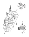
- the filter 10 operates to vary selectively the spectral composition of visible light from a radiant source 11 to transmit a predetermined number of colours of different saturation and hue.
- the preferred structure of the filter 10 comprises, from left to right along an optical axis OA, a magenta dye polariser 12, a first liquid crystal cell 14, an ordinary linear or plane polariser 16, a second liquid crystal cell 18, a cyan dye polariser 20, a third liquid crystal cell 22, and a yellow dye polariser 24.
- the dye polarisers 12, 20 and 24 preferably each comprise a stretched polyvinyl alcohol sheet treated with an absorbing dye so that each dye polariser absorbs a different part of the visible spectrum and plane polarisers that part of the visible spectrum which is absorbed by the dye while transmitting the nonabsorbed part of the visible spectrum unpolarised.
- the dye polarisers 12, 20 and 24 may be fabricated, and dyes for them selected, in the manner described in U.S. Patents Nos. 2,328,219 and 4,025,164.
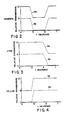
- the preferred relative transmission characteristics of the dye polarisers 12, 20 and 24 are represented by the curves 50, 54 and 58 in Figures 2, 3 and 4, respectively.
- the relative transmission characteristics for each dye polariser represents the shape of the absorbed spectra for the particular dye incorporated. Absolute transmission characteristics which may be desired for a particular application can be easily controlled in a well known manner through the use of appropriate dye concentration levels.
- the dye polariser 12 is preferably provided with a magenta dye and plane polarises green light (approximately .5 to .6 Ilm) while transmitting blue light (approximately .4 to .5 Ilm) and red light (approximately .6 to .7 ⁇ m) unpolarised.
- the transmission axis 13 of the dye polariser 12 is preferably arranged horizontally so that green light is polarised in a plane parallel to the transmission axis 13.
- the dye polariser 20 is provided with a cyan dye and plane polarises and absorbs red light while transmitting blue and green light unpolarised.
- the transmission axis 17 of the dye polariser 20 is also arranged horizontally and therefore red light is polarised thereby in a plane which is both parallel to the transmission axis 17 and also to the transmission axis 13 of the dye polariser 12.
- the dye polariser 24 is provided with a yellow dye and absorbs and plane polarises blue light while transmitting, unpolarised, green and red light.
- the transmission axis 19 of the dye polariser 24 is arranged vertically so that blue light polarised thereby exits the dye polariser 24 in a plane which is parallel to its transmission axis 19.
- the plane polariser 16 operates in a well known manner to plane polarise substantially uniformly all wavelengths of the visible spectrum.
- the transmission axis 15 of the plane polariser 16 is arranged vertically.
- the dye polarisers 12, 20 and 24 and the plane polariser 16 are positioned with respect to one another with their polarising transmission axes at angular increments of 90-degrees azimuth.
- the liquid crystal cells 14, 18, 22 are of the twisted nematic type described in an article authored by M. Schadt and W. Helfrich which appeared in the Applied Physics Letters, vol. 19, No. 4, 15 February 1971, and entitled "Voltage-Dependent Optical Activity Of A Twisted Nematic Liquid Crystal".
- Each liquid crystal cell 14, 18, 22, comprises a suitable nematic liquid crystal material placed between two glass plates each of which is provided with a conductive coating.
- the liquid crystal material for the cell 14 is designated at 30 and its glass plates with appropriate conductive control layers thereon are designated at 26 and 28; the liquid crystal material for the cell 18 is designated at 38 while its glass plates with conductive coatings thereon are designated at 34 and 36; and the liquid crystal material for the cell 22 is designated at 46 while its glass plates with conductive coatings thereon are designated at 42 and 44.
- the liquid crystal cells, 14,18 and 22, operate in the manner described in the aforementioned article to vary the rotation of linearly polarised light continuously from 0- degrees to 90-degrees in accordance with the voltage applied across their respective conducting layers.
- the required voltages can be applied to the respective conductive coatings of the liquid crystal cells, 14, 18 and 22, by well known variable voltage sources 32, 40 and 48.
- Each of the liquid crystal cells, 14, 18 and 22, is arranged to cause a 90-degree rotation of the axis of polarisation for the entire spectrum when not energised and when fully energised to transmit plane polarised light without rotation.
- plane polarised light incident upon any of the liquid crystal cells, 14, 18, 22, is -rotated through an angle less than 90-degrees as designated respectively at 81, 82, and 83.
- the angles 8 1 , 82 and 8 3 depend on the voltage applied to the respective liquid crystals cells, 14, 18 and 22.
- Each of the dye polarisers 12, 20 and 24, is arranged in the foregoing manner with respect to the plane polariser 16 so that any one of the dye polarisers (12, 20 or 24), in combination with the plane polariser 16 transmits the entire visible spectrum when the plane in which the light is polarised by the dye polariser is parallel to the transmission axis of the plane polariser 16 and transmits its designated colour, i.e. magenta, cyan and yellow, by absorbing the camplement thereof when the plane in which the light is polarised by the dye polariser is crossed, i.e. rotated by the angles, 6 1 , 8 2 and 8 3 through the liquid crystal cells, 14, 18 and 22, with the transmission axis of the plane polariser 16.
- any one of the dye polarisers (12, 20 or 24) in combination with the plane polariser 16 transmits the entire visible spectrum when the plane in which the light is polarised by the dye polariser is parallel to the transmission axis of the plane polariser 16 and transmits its designated
- the curve 52 in Fig. 2 represents the colour transmitted by the magenta dye polariser 12 when crossed with the plane polariser 16 through the fully energised liquid cell 14;
- the curve 56 of Fig. 3 represents the colour transmitted by the cyan dye polariser 20 when crossed with the plane polariser 16 through the fully energised liquid crystal cell 18;
- the curve 60 of Fig. 4 represents the colour transmitted by the yellow dye polariser 24 when crossed with the plane polariser 16 through the fully energised liquid crystal cell 22.
- the magenta filter 12 is thus optically parallel to the transmission axis of the plane polariser 16 and only partially absorbs green light.
- the cyan dye polariser 20 is optically parallel to the transmission axis of the plane polariser 16 and only partially absorbs red light because all three colours emerge from plane polariser 16 parallel to its axis 15 and are then rotated by 90-degrees by the liquid crystal cell 40 so that they are parallel to the transmission axis 17 of the cyan dye polariser 20.
- the yellow dye polariser 24 is optically parallel to the transmission axis of the plane polariser 16 and only partially absorbs blue light because all three colours emerge from the cyan dye polariser 20 parallel to its transmission axis 17 and are then rotated by 90-degrees by the liquid crystal cell 22 so that they are parallel to the transmission axis 19 of the dye polariser 24.
- the liquid crystal material loses its "twist" and each of the cells, 14, 18 and 22, passes polarised light without rotation.
- the filter 10 in addition to providing the colours listed in Table 1 can create any colour display which is within the dye gamut offered by the dye polarisers 12, 20, and 24. These other colours can be achieved by applying to the liquid crystal control cells 14, 18 and 22 appropriate voltage levels which are below the predetermined level of their fully energised state.
- the angles through which plane polarised light is rotated depend on the voltage applied to the liquid crystal cells 14,18 and 22 and are designated respectively as ⁇ 1, 82 and 83. Given that the three angles of rotation are designated by 81, 82 and 83, then the red, green and blue transmissions for the filter 10 are as follows:
- 83 must have a range of 180° rather than 90°. This may be accomplished by replacing the liquid crystal cell 22 with a pair of such cells in tandem each of which rotates plane polarised light through 90°. With such a tandem cell in place of the cell 22, the colours listed in Table 1 would still be available through the use of two appropriate voltage levels for the tandem cell to provide a 0° or 90° rotation.
- the filter 10 has the magenta dye polariser 12 on one side of the plane polariser 16 because its absorption is central in the visible spectrum.
- the cyan dye polariser 20 and the yellow dye polariser 24, which are together on the opposite side of the plane polariser 16 have the greatest possible lack of overlap of their spectral absorption characteristics.
- the dye polarisers 12, 20 and 24, the plane polariser 16, and the twisted nematic liquid crystal cells 14, 18 and 22 have been arranged along the optical path, OA, of the filter 10 in a predetermined manner to modify the spectral content of visible light incident on the filter 10 so that the filter 10 transmits any one of a predetermined number of colours the saturation and hue of which are related to the voltages applied to the twisted nematic liquid crystal cells 14, 18 and 22.
- the present invention operates in a manner similar to a subtractive colour mixing system in that the different amounts of dye in the colour mixing system are simulated by the aforementioned polarisation changes.
- Colour saturation is controlled by how much the liquid crystal cells, 14, 18 and 22, are rotated, and hue is controlled by which dye polarisers, 12, 20 and 24, are crossed with linear polariser 16.
- What is most significant about the colour filter 10 is that it can be used to adjust both saturation and hue over a substantial range.
- Fig. 5 there is shown the preferred embodiment of the filter 10 of the invention in combination with a mirror 62 placed to the right of the yellow dye polariser 24.
- the filter 10 may be used in a reflection mode because light reflected from the mirror 62 is treated in the same manner after having been reflected off the mirror 62 as if it were light transmitted through the filter 10 by the source 11.
- the net effect on the colour of light reflected from the mirror 62 is the same as if the source 11 were in place of the mirror 62.
- the filter 10 may be modified in a well known manner to transmit alphanumeric information in colour. This can be accomplished as illustrated in Fig. 6 by arranging the conductive layer in the form of a well known seven-segment pattern designated at 66 on a glass plate of a liquid crystal cell such as that designated at 64. Different areas of the pattern 66 can be individually controlled through a plurality of leads 68 which can be selectively actuated in an appropriate manner by well known electronic devices.
- the pattern 66 or similar alphanumeric pattern can be placed in each of the plates of the liquid crystal cells, 14, 18 and 22, in alignment with one another along the optical axis, OA, and selectively actuated in the manner previously described.
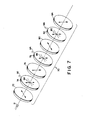
- the magenta dye polariser is designated at 72, the plane polariser at 76, the cyan dye polariser at 80 and the yellow dye polariser at 84-all arranged as previously described with respect to the preferred embodiment of the invention.
- a well known halfwave plate 74 which can be manually rotated through the use of an appropriate handle 92; between the plane polarisers 76 and the cyan dye polariser 80 is placed another halfwave plate which is designated at 78 and includes a handle 94 for manual rotation thereof; and between the cyan dye polariser 80 and the yellow dye polariser 84 is a third halfwave plate which is designated at 82 and includes a handle 96 for manual rotation thereof.
- Halfwave plates such as those designated at 74, 78 and 82 operate to convert linearly polarised light into linearly polarised light with a different azimuth.
- the plane polarised light passes through the halfwave plate unchanged.
- the fast or slow axis of a halfwave plate rotates the angle of polarisation by an amount which is twice the angle between the planes of the plane polarised light and the plane of the fast or slow axis of tha halfwave plate.
- the fast axes of the halfwave plates 74, 78 and 82 are designated in Fig.
Landscapes
- Physics & Mathematics (AREA)
- Nonlinear Science (AREA)
- Mathematical Physics (AREA)
- Chemical & Material Sciences (AREA)
- Crystallography & Structural Chemistry (AREA)
- General Physics & Mathematics (AREA)
- Optics & Photonics (AREA)
- Liquid Crystal (AREA)
- Devices For Indicating Variable Information By Combining Individual Elements (AREA)
Applications Claiming Priority (2)
| Application Number | Priority Date | Filing Date | Title |
|---|---|---|---|
| US06/205,660 US4416514A (en) | 1980-11-10 | 1980-11-10 | Color filter |
| US205660 | 1988-06-13 |
Publications (3)
| Publication Number | Publication Date |
|---|---|
| EP0052000A2 EP0052000A2 (en) | 1982-05-19 |
| EP0052000A3 EP0052000A3 (en) | 1983-01-12 |
| EP0052000B1 true EP0052000B1 (en) | 1987-01-21 |
Family
ID=22763116
Family Applications (1)
| Application Number | Title | Priority Date | Filing Date |
|---|---|---|---|
| EP81305300A Expired EP0052000B1 (en) | 1980-11-10 | 1981-11-06 | Variable colour filters |
Country Status (5)
| Country | Link |
|---|---|
| US (1) | US4416514A (OSRAM) |
| EP (1) | EP0052000B1 (OSRAM) |
| JP (1) | JPS57150820A (OSRAM) |
| CA (1) | CA1168489A (OSRAM) |
| DE (1) | DE3175861D1 (OSRAM) |
Families Citing this family (79)
| Publication number | Priority date | Publication date | Assignee | Title |
|---|---|---|---|---|
| US4617562A (en) * | 1983-04-11 | 1986-10-14 | Klotz Dell E | Multicolored liquid crystal display |
| EP0139643B1 (en) * | 1983-04-21 | 1989-11-29 | Beckman Instruments, Inc. | Liquid crystal tuned birefringent filter |
| US4758818A (en) * | 1983-09-26 | 1988-07-19 | Tektronix, Inc. | Switchable color filter and field sequential full color display system incorporating same |
| US4635051A (en) * | 1983-09-26 | 1987-01-06 | Tektronix, Inc. | High-speed electro-optical light gate and field sequential full color display system incorporating same |
| JPS6095515A (ja) * | 1983-09-26 | 1985-05-28 | テクトロニツクス・インコーポレイテツド | カラーフイルタ |
| EP0163366A1 (en) * | 1984-04-02 | 1985-12-04 | Tektronix, Inc. | Electro-optic display with optimum transmissivity and viewing angle performance |
| US4611889A (en) * | 1984-04-04 | 1986-09-16 | Tektronix, Inc. | Field sequential liquid crystal display with enhanced brightness |
| US4674841A (en) * | 1985-03-08 | 1987-06-23 | Tektronix, Inc. | Color filter switchable among three state via a variable retarder |
| JP2556831B2 (ja) * | 1985-05-11 | 1996-11-27 | オリンパス光学工業株式会社 | 光学的ロ−パスフイルタ−及びこれを用いた撮像装置 |
| CA1270583A (en) * | 1986-02-05 | 1990-06-19 | Frederick J. Porter | Color selectable liquid crystal display system |
| US4867536A (en) * | 1986-02-05 | 1989-09-19 | Ford Motor Company | Color selectable liquid crystal display system |
| DE3721751A1 (de) * | 1987-07-01 | 1989-01-12 | Eps Elektronik | Optoelektronisches filter vorzugsweise fuer videokameras |
| CA1268271C (en) * | 1987-11-06 | 1990-04-24 | Electro-optic animated displays and indicators | |
| US5142388A (en) * | 1987-11-10 | 1992-08-25 | Futaba Denshi Kogyo K.K. | Color display device having liquid crystal cell and fluorescent display with two different luminous sections |
| US5153568A (en) * | 1988-07-21 | 1992-10-06 | Proxima Corporation | Liquid crystal display panel system and method of using same |
| US5302946A (en) * | 1988-07-21 | 1994-04-12 | Leonid Shapiro | Stacked display panel construction and method of making same |
| US5089810A (en) * | 1990-04-09 | 1992-02-18 | Computer Accessories Corporation | Stacked display panel construction and method of making same |
| US5298892A (en) * | 1988-07-21 | 1994-03-29 | Proxima Corporation | Stacked display panel construction and method of making same |
| US4974944A (en) * | 1988-07-21 | 1990-12-04 | Hewlett-Packard Company | Optical nonreciprocal device |
| US5113270A (en) * | 1988-10-19 | 1992-05-12 | Fergason James L | Variable density light control apparatus |
| US5523863A (en) * | 1988-10-19 | 1996-06-04 | Fergason; James L. | Controlled liquid crystal optical polarizer method and apparatus |
| US5847790A (en) * | 1989-02-16 | 1998-12-08 | S.T. Lagerwall S.A.R.L. | Liquid crystal devices using a linear electro-optic effect |
| USRE36654E (en) * | 1989-03-28 | 2000-04-11 | In Focus Systems, Inc. | Stacked LCD color display |
| US5050965A (en) * | 1989-09-01 | 1991-09-24 | In Focus Systems, Inc. | Color display using supertwisted nematic liquid crystal material |
| EP0388976A3 (en) * | 1989-03-28 | 1991-06-05 | In Focus Systems, Inc. | Color display |
| US4917465A (en) * | 1989-03-28 | 1990-04-17 | In Focus Systems, Inc. | Color display system |
| US4966441A (en) * | 1989-03-28 | 1990-10-30 | In Focus Systems, Inc. | Hybrid color display system |
| US5264951A (en) * | 1990-04-09 | 1993-11-23 | Victor Company Of Japan, Ltd. | Spatial light modulator system |
| JPH05307176A (ja) * | 1990-06-29 | 1993-11-19 | Proxima Corp | 表示装置及び表示方法 |
| US5206749A (en) * | 1990-12-31 | 1993-04-27 | Kopin Corporation | Liquid crystal display having essentially single crystal transistors pixels and driving circuits |
| US5751261A (en) * | 1990-12-31 | 1998-05-12 | Kopin Corporation | Control system for display panels |
| US5444557A (en) * | 1990-12-31 | 1995-08-22 | Kopin Corporation | Single crystal silicon arrayed devices for projection displays |
| US5661371A (en) * | 1990-12-31 | 1997-08-26 | Kopin Corporation | Color filter system for light emitting display panels |
| US5122887A (en) * | 1991-03-05 | 1992-06-16 | Sayett Group, Inc. | Color display utilizing twisted nematic LCDs and selective polarizers |
| US5347378A (en) * | 1991-04-04 | 1994-09-13 | Displaytech, Inc. | Fast switching color filters for frame-sequential video using ferroelectric liquid crystal color-selective filters |
| JP2829149B2 (ja) * | 1991-04-10 | 1998-11-25 | シャープ株式会社 | 液晶表示装置 |
| EP0528542B1 (en) * | 1991-07-19 | 1998-09-16 | SHARP Corporation | Optical modulating element and apparatuses using it |
| US5184156A (en) * | 1991-11-12 | 1993-02-02 | Reliant Laser Corporation | Glasses with color-switchable, multi-layered lenses |
| US6511187B1 (en) | 1992-02-20 | 2003-01-28 | Kopin Corporation | Method of fabricating a matrix display system |
| JPH05241143A (ja) * | 1992-02-28 | 1993-09-21 | Dainippon Printing Co Ltd | 反射型液晶表示装置 |
| US5315418A (en) * | 1992-06-17 | 1994-05-24 | Xerox Corporation | Two path liquid crystal light valve color display with light coupling lens array disposed along the red-green light path |
| JP3329887B2 (ja) * | 1992-06-17 | 2002-09-30 | ゼロックス・コーポレーション | 2光路液晶ライトバルブカラー表示装置 |
| US5325218A (en) * | 1992-12-31 | 1994-06-28 | Minnesota Mining And Manufacturing Company | Cholesteric polarizer for liquid crystal display and overhead projector |
| US5371618A (en) * | 1993-01-05 | 1994-12-06 | Brite View Technologies | Color liquid crystal display employing dual cells driven with an EXCLUSIVE OR relationship |
| DE4317140A1 (de) * | 1993-05-22 | 1994-11-24 | Andreas Biedermann | Variables Farbfilter |
| FR2709854B1 (fr) * | 1993-09-07 | 1995-10-06 | Sextant Avionique | Dispositif de visualisation à couleurs optimisées. |
| IL111108A (en) * | 1993-10-01 | 1998-08-16 | Hughes Training Inc | Defective color display with liquid crystal and active matrix with integral light reduction |
| SG47360A1 (en) * | 1994-11-14 | 1998-04-17 | Hoffmann La Roche | Colour display with serially-connected lc filters |
| US5689317A (en) * | 1995-03-22 | 1997-11-18 | Cambridge Research Instrumentation, Inc. | Tunable color filter |
| US5822021A (en) * | 1996-05-14 | 1998-10-13 | Colorlink, Inc. | Color shutter liquid crystal display system |
| US6183091B1 (en) | 1995-04-07 | 2001-02-06 | Colorlink, Inc. | Color imaging systems and methods |
| US6707516B1 (en) | 1995-05-23 | 2004-03-16 | Colorlink, Inc. | Single-panel field-sequential color display systems |
| US5999240A (en) | 1995-05-23 | 1999-12-07 | Colorlink, Inc. | Optical retarder stack pair for transforming input light into polarization states having saturated color spectra |
| US5751384A (en) | 1995-05-23 | 1998-05-12 | The Board Of Regents Of The University Of Colorado | Color polarizers for polarizing an additive color spectrum along a first axis and it's compliment along a second axis |
| US6882384B1 (en) * | 1995-05-23 | 2005-04-19 | Colorlink, Inc. | Color filters and sequencers using color selective light modulators |
| US6252638B1 (en) | 1995-05-23 | 2001-06-26 | Colorlink, Inc. | Color controllable illumination device, indicator lights, transmissive windows and color filters employing retarder stacks |
| US6049367A (en) * | 1995-05-23 | 2000-04-11 | Colorlink, Inc. | Polarization manipulating device modulator with retarder stack which preconditions light for modulation and isotropic states |
| US5929946A (en) * | 1995-05-23 | 1999-07-27 | Colorlink, Inc. | Retarder stack for preconditioning light for a modulator having modulation and isotropic states of polarization |
| US6417892B1 (en) | 1995-05-23 | 2002-07-09 | Colorlink, Inc. | Color filters, sequencers and displays using color selective light modulators |
| US6273571B1 (en) | 1995-05-23 | 2001-08-14 | Colorlink, Inc. | Display architectures using an electronically controlled optical retarder stack |
| JPH095745A (ja) * | 1995-06-07 | 1997-01-10 | Xerox Corp | カラー液晶ディスプレイ装置の光ファイバフェースプレート |
| US5892559A (en) * | 1996-11-25 | 1999-04-06 | Colorlink, Inc. | Chromaticity compensating liquid crystal filter |
| US6078303A (en) * | 1996-12-19 | 2000-06-20 | Colorado Microdisplay, Inc. | Display system having electrode modulation to alter a state of an electro-optic layer |
| US5920298A (en) * | 1996-12-19 | 1999-07-06 | Colorado Microdisplay, Inc. | Display system having common electrode modulation |
| US6046716A (en) | 1996-12-19 | 2000-04-04 | Colorado Microdisplay, Inc. | Display system having electrode modulation to alter a state of an electro-optic layer |
| SE511560C2 (sv) * | 1998-09-30 | 1999-10-18 | Richard Ryan Magnusson | Filteranordning och utrustning innefattande filteranordningen |
| US6208393B1 (en) * | 1998-09-30 | 2001-03-27 | Intel Corporation | Liquid crystal color filter with integrated infrared blocking |
| US6516661B1 (en) | 1999-01-28 | 2003-02-11 | Simmonds Precision Products, Inc. | Volume measurement system and method for volume element counting |
| TW546555B (en) | 2000-05-16 | 2003-08-11 | Asulab Sa | Display assembly with chromatic contrast inversion |
| EP1156360B1 (fr) * | 2000-05-16 | 2017-01-18 | Asulab S.A. | Ensemble d'affichage à inversion chromatique de contraste |
| US7027224B2 (en) * | 2001-01-31 | 2006-04-11 | Sharp Laboratories Of America, Inc. | Wave plate mounting |
| WO2002099516A2 (en) * | 2001-06-01 | 2002-12-12 | Kent State University | Birefringent filter-based color generation scheme for a passive matrix display device |
| US7170679B2 (en) * | 2002-09-18 | 2007-01-30 | Vision Quest Lighting, Inc. | Optically active color filter |
| US6888659B2 (en) * | 2002-12-10 | 2005-05-03 | Jds Uniphase Inc. | Polarization controller |
| US20080094689A1 (en) * | 2004-11-12 | 2008-04-24 | Koninklijke Philips Electronics, N.V. | Bright Full Color Reflective Display |
| JP4645714B2 (ja) * | 2008-09-19 | 2011-03-09 | 株式会社デンソー | 画像処理装置 |
| EP3274765A4 (en) * | 2015-03-23 | 2018-10-17 | Intematix Corporation | Photoluminescence color display |
| US10901128B2 (en) * | 2015-06-26 | 2021-01-26 | The Arizona Board Of Regents On Behalf Of The University Of Arizona | Compound dichroic polarizers with wavelength dependent transmission axes |
| US10866429B2 (en) * | 2017-01-24 | 2020-12-15 | Gary Sharp Innovations, Llc | Tunable color enhancement filter |
Family Cites Families (19)
| Publication number | Priority date | Publication date | Assignee | Title |
|---|---|---|---|---|
| US2493200A (en) * | 1946-05-31 | 1950-01-03 | Polaroid Corp | Variable polarizing color filter |
| US2586635A (en) * | 1947-06-27 | 1952-02-19 | Rca Corp | Color control system |
| US2834254A (en) * | 1953-10-22 | 1958-05-13 | Du Mont Allen B Lab Inc | Electronic color filter |
| BE755563A (fr) * | 1969-09-02 | 1971-03-01 | Polaroid Corp | Dispositif de filtrage variable de lumiere |
| US3774988A (en) * | 1969-09-02 | 1973-11-27 | Polaroid Corp | Variable light-filtering device |
| US3703329A (en) * | 1969-12-29 | 1972-11-21 | Rca Corp | Liquid crystal color display |
| US3936147A (en) * | 1972-11-22 | 1976-02-03 | Minolta Camera Kabushiki Kaisha | Variable characteristic light filter |
| US4019808A (en) * | 1973-06-09 | 1977-04-26 | Fraunhofer-Gesellschaft Zur Forderung Der Angewandten Forschung E.V. | Arrangement for a polychrome display |
| GB1469638A (en) * | 1973-07-18 | 1977-04-06 | Secr Defence | Liquid crystal display device |
| CA1036699A (en) * | 1974-02-28 | 1978-08-15 | Akio Moriyama | Electro-optical display device |
| NL7408108A (nl) * | 1974-06-18 | 1975-12-22 | Philips Nv | Inrichting voor het weergeven van tekens voor- zien van een getwistnematisch vloeibaar kristal. |
| US4068926A (en) * | 1974-11-13 | 1978-01-17 | Japan Suncrux Co., Ltd. | Liquid crystal display device for displaying colored patterns |
| CH582894A5 (OSRAM) * | 1975-03-17 | 1976-12-15 | Bbc Brown Boveri & Cie | |
| US4097128A (en) * | 1975-04-24 | 1978-06-27 | Tokyo Shibaura Electric Co., Ltd. | Liquid crystal color display devices |
| JPS5259597A (en) * | 1975-11-11 | 1977-05-17 | Seiko Instr & Electronics Ltd | Display unit |
| JPS533842A (en) * | 1976-07-01 | 1978-01-13 | Toshiba Corp | Liquid crystalline color indication element |
| JPS53101296A (en) * | 1977-02-16 | 1978-09-04 | Seiko Epson Corp | Display unit |
| US4097130A (en) * | 1977-03-11 | 1978-06-27 | General Electric Company | Multi-colored liquid crystal displays |
| JPS5722218Y2 (OSRAM) * | 1977-11-24 | 1982-05-14 |
-
1980
- 1980-11-10 US US06/205,660 patent/US4416514A/en not_active Expired - Lifetime
-
1981
- 1981-11-06 EP EP81305300A patent/EP0052000B1/en not_active Expired
- 1981-11-06 DE DE8181305300T patent/DE3175861D1/de not_active Expired
- 1981-11-09 CA CA000389747A patent/CA1168489A/en not_active Expired
- 1981-11-10 JP JP56180275A patent/JPS57150820A/ja active Granted
Also Published As
| Publication number | Publication date |
|---|---|
| EP0052000A3 (en) | 1983-01-12 |
| DE3175861D1 (en) | 1987-02-26 |
| US4416514A (en) | 1983-11-22 |
| JPS57150820A (en) | 1982-09-17 |
| EP0052000A2 (en) | 1982-05-19 |
| CA1168489A (en) | 1984-06-05 |
| JPH0366646B2 (OSRAM) | 1991-10-18 |
Similar Documents
| Publication | Publication Date | Title |
|---|---|---|
| EP0052000B1 (en) | Variable colour filters | |
| US4497543A (en) | Liquid crystal display with colors from dye and polarizer mixed | |
| US5122887A (en) | Color display utilizing twisted nematic LCDs and selective polarizers | |
| US4232948A (en) | Liquid crystal display device | |
| US5548422A (en) | Notch filters with cholesteric polarizers with birefringent film and linear polarizer | |
| US5999240A (en) | Optical retarder stack pair for transforming input light into polarization states having saturated color spectra | |
| US3967881A (en) | Liquid crystal display | |
| EP0898841B1 (en) | Color selective light modulators | |
| EP0393191B1 (en) | Liquid crystal display | |
| US4610507A (en) | Color liquid crystal display device having multicolor polarizers | |
| US5929946A (en) | Retarder stack for preconditioning light for a modulator having modulation and isotropic states of polarization | |
| US5923392A (en) | Liquid crystal display device | |
| US5835166A (en) | Chiral nematic liquid crystal polarization modulated color display for stereoscopic viewing device | |
| EP0138454B1 (en) | Switchable color filter and field sequential full color display system incorporating same | |
| US6049367A (en) | Polarization manipulating device modulator with retarder stack which preconditions light for modulation and isotropic states | |
| CA1305242C (en) | Multicolor liquid crystal display | |
| US20020171793A1 (en) | Achromatic compound retarder | |
| EP0699938A2 (en) | Liquid crystal display | |
| JPH11503247A (ja) | 液晶アクロマティク複合リターダ | |
| JPH11515117A (ja) | 切替え可能な色消し偏光回転子 | |
| KR0131015B1 (ko) | 액정표시 소자 | |
| CA2009319C (en) | Liquid crystal display device | |
| EP0895116A2 (en) | Liquid crystal color shutters using reflective polarizer | |
| JPS60159823A (ja) | カラ−液晶表示装置 | |
| US4309084A (en) | Magneto-optical light modulator |
Legal Events
| Date | Code | Title | Description |
|---|---|---|---|
| PUAI | Public reference made under article 153(3) epc to a published international application that has entered the european phase |
Free format text: ORIGINAL CODE: 0009012 |
|
| AK | Designated contracting states |
Designated state(s): CH DE FR GB IT NL |
|
| PUAL | Search report despatched |
Free format text: ORIGINAL CODE: 0009013 |
|
| AK | Designated contracting states |
Designated state(s): CH DE FR GB IT LI NL |
|
| RHK1 | Main classification (correction) |
Ipc: G02F 1/137 |
|
| 17P | Request for examination filed |
Effective date: 19830610 |
|
| GRAA | (expected) grant |
Free format text: ORIGINAL CODE: 0009210 |
|
| AK | Designated contracting states |
Kind code of ref document: B1 Designated state(s): CH DE FR GB IT LI NL |
|
| PG25 | Lapsed in a contracting state [announced via postgrant information from national office to epo] |
Ref country code: LI Effective date: 19870121 Ref country code: IT Free format text: LAPSE BECAUSE OF FAILURE TO SUBMIT A TRANSLATION OF THE DESCRIPTION OR TO PAY THE FEE WITHIN THE PRESCRIBED TIME-LIMIT;WARNING: LAPSES OF ITALIAN PATENTS WITH EFFECTIVE DATE BEFORE 2007 MAY HAVE OCCURRED AT ANY TIME BEFORE 2007. THE CORRECT EFFECTIVE DATE MAY BE DIFFERENT FROM THE ONE RECORDED. Effective date: 19870121 Ref country code: CH Effective date: 19870121 |
|
| REF | Corresponds to: |
Ref document number: 3175861 Country of ref document: DE Date of ref document: 19870226 |
|
| ET | Fr: translation filed | ||
| REG | Reference to a national code |
Ref country code: CH Ref legal event code: PL |
|
| PLBE | No opposition filed within time limit |
Free format text: ORIGINAL CODE: 0009261 |
|
| STAA | Information on the status of an ep patent application or granted ep patent |
Free format text: STATUS: NO OPPOSITION FILED WITHIN TIME LIMIT |
|
| 26N | No opposition filed | ||
| PGFP | Annual fee paid to national office [announced via postgrant information from national office to epo] |
Ref country code: FR Payment date: 19971015 Year of fee payment: 17 |
|
| PGFP | Annual fee paid to national office [announced via postgrant information from national office to epo] |
Ref country code: GB Payment date: 19971017 Year of fee payment: 17 |
|
| PGFP | Annual fee paid to national office [announced via postgrant information from national office to epo] |
Ref country code: NL Payment date: 19971021 Year of fee payment: 17 |
|
| PGFP | Annual fee paid to national office [announced via postgrant information from national office to epo] |
Ref country code: DE Payment date: 19971027 Year of fee payment: 17 |
|
| PG25 | Lapsed in a contracting state [announced via postgrant information from national office to epo] |
Ref country code: GB Free format text: LAPSE BECAUSE OF NON-PAYMENT OF DUE FEES Effective date: 19981106 |
|
| PG25 | Lapsed in a contracting state [announced via postgrant information from national office to epo] |
Ref country code: NL Free format text: LAPSE BECAUSE OF NON-PAYMENT OF DUE FEES Effective date: 19990601 |
|
| GBPC | Gb: european patent ceased through non-payment of renewal fee |
Effective date: 19981106 |
|
| PG25 | Lapsed in a contracting state [announced via postgrant information from national office to epo] |
Ref country code: FR Free format text: LAPSE BECAUSE OF NON-PAYMENT OF DUE FEES Effective date: 19990730 |
|
| NLV4 | Nl: lapsed or anulled due to non-payment of the annual fee |
Effective date: 19990601 |
|
| REG | Reference to a national code |
Ref country code: FR Ref legal event code: ST |
|
| PG25 | Lapsed in a contracting state [announced via postgrant information from national office to epo] |
Ref country code: DE Free format text: LAPSE BECAUSE OF NON-PAYMENT OF DUE FEES Effective date: 19990901 |