EP0051950A2 - Fahrbare Richtmaschine für Rohre - Google Patents
Fahrbare Richtmaschine für Rohre Download PDFInfo
- Publication number
- EP0051950A2 EP0051950A2 EP81305037A EP81305037A EP0051950A2 EP 0051950 A2 EP0051950 A2 EP 0051950A2 EP 81305037 A EP81305037 A EP 81305037A EP 81305037 A EP81305037 A EP 81305037A EP 0051950 A2 EP0051950 A2 EP 0051950A2
- Authority
- EP
- European Patent Office
- Prior art keywords
- machine
- tube
- hydraulic
- rollers
- roller
- Prior art date
- Legal status (The legal status is an assumption and is not a legal conclusion. Google has not performed a legal analysis and makes no representation as to the accuracy of the status listed.)
- Withdrawn
Links
Images


Classifications
-
- B—PERFORMING OPERATIONS; TRANSPORTING
- B21—MECHANICAL METAL-WORKING WITHOUT ESSENTIALLY REMOVING MATERIAL; PUNCHING METAL
- B21D—WORKING OR PROCESSING OF SHEET METAL OR METAL TUBES, RODS OR PROFILES WITHOUT ESSENTIALLY REMOVING MATERIAL; PUNCHING METAL
- B21D3/00—Straightening or restoring form of metal rods, metal tubes, metal profiles, or specific articles made therefrom, whether or not in combination with sheet metal parts
- B21D3/02—Straightening or restoring form of metal rods, metal tubes, metal profiles, or specific articles made therefrom, whether or not in combination with sheet metal parts by rollers
- B21D3/04—Straightening or restoring form of metal rods, metal tubes, metal profiles, or specific articles made therefrom, whether or not in combination with sheet metal parts by rollers arranged on axes skew to the path of the work
Definitions
- This invention relates to a machine for straightening tubes, particularly scaffold tubes.
- the invention provides such a machine.
- a tube straightening machine comprising a chassis and, mounted on said chassis a prime mover, a hydraulic pump driven by said prime mover, a plurality of rollers through which tubes may be fed for straightening, one or more hydraulic motors for driving said rollers to rotate about their longitudinal axis to draw tubes through during bending and hydraulic circuit means connecting said pump with the or each hydraulic motor, said hydraulic circuit means incorporating means for controlling the operation of said hydraulic motor or motors.
- the chassis is supported by four road wheels.
- the two rear wheels may be mounted on a rigid axle, and the two front wheels steerable on a driven axle. In an-alternative, two of the wheels are driven, the the other two steerable.
- the chassis may alternatively be supported on a fixed base or legs, or the machine may be made semi-portable by supporting the chassis on skids.
- a prime mover is mounted on the chassis and drives a hydraulic pump.
- the prime mover may for example be a petrol or diesel engine, or an electric motor. Fluid from the pump can be directed to a hydraulic drive motor for driving a plurality of rollers through which the tubes are fed for straightening.
- each roller is driven by its own individual hydraulic drive motor, thus providing a power feed for the tubes as well as straightening them.
- the rollers are arranged on opposite sides of the path of the tubes - for example two on each side.
- the roller or rollers on one side of the path may be mounted on a sub-frame which can be moved laterally with respect to the path of the tube clamped in position to apply pressure to the tube and in order to take up any wear in the rollers.
- the roller or rollers may be pivoted about their axis as will be explained in more detail later.
- an extensible feed-out trough lined with resilient material such as plastics and into which the straightened tube runs after passing through the straightening rollers.
- the hydraulic pump is also operable to supply fluid to a drive motor for the road wheels.
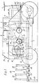
- the machine comprises a chassis 2 and four road wheels 2, 3.
- the rear wheels 2 are mounted on a rigid axle 4 and the front wheels 3 are steerable by means of a steering wheel 5 mounted in front of a driver's seat 6.
- Mounted on the chassis is a prime mover in the form of an internal combustion engine 7 having an air filter 8 and a radiator 9.
- the output shaft of the engine is coupled via a flexible coupling 10 to a hydraulic pump 11, which is preferably of the variable-displacement type - see later. Fluid from the pump is selectively passed to a hydraulic motor 12 which drives the front wheels 3 and to a plurality of roller drive motors 13 ( Figure,3), to be referred to later.
- An oil tank 14 acts as a reservoir for the hydraulic circuit, and operation of the machine is controlled from a control panel 15.
- Tubes to be pre-straightened are fed in from left to right in Figures 1 and 2 in the approximate line of the arrow A in Figure 2.
- the tubes are passed between rollers 17 and a curved anvil 18 which is moveable horizontally under power from a hydraulic ram 19.
- tubes to be straightened are introduced into the machine at the left-hand end in Figures 1 and 2 along a path coincident with the centre line of the machine.
- Tubes enter a telescopic feed-in unit 20 which comprises a support bar 21 having at its outer end three telescopic sections 22, 23 and 24 of smaller size.
- the outermost section 22 carries a leg 25 which may be folded down to a support position, shown in Figure 1 to support the feed-in unit on the ground.
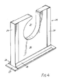
- Each section of the feed-in unit, as well as the bar 21 carries a respective feed-in guide 26 which takes the form shown in Figure 4.
- Each guide 26 comprises a base 27 which is attached to the respective section of the support bar 21 and on which is mounted a framework made up of steel angle 28 and steel channel 29 which carries an insert 30 made of high density polyethylene.
- the insert 30 is equipped with an aperture 31 through which pipe to be straightened is passed. It will be seen from Figure 4 that the neck of the aperture is misplaced. This is to contain the tube which otherwise has a tendency to jump out due to its rotation once it enters the machine.
- the inserts 26 are positioned such that their respective apertures 31 fall as the machine is approached, this feature assisting the introduction of bent pipe into the machine along the correct axis.
- the feed-in unit When the machine is being moved from place to place, the feed-in unit is retracted from the operative position shown in Figures 1 and 2 to an inoperative position in which the innermost feed-in guide 26 abuts against a vertical plate 32.
- the feed-in unit may be clamped in its operative position by means of cam locks 33.
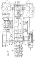
- the tube to be straightened is passed into the central part of the machine by being placed into the feed-in guides 26 and pushed into the machine to the first, 34, of four straightening rollers 34 to 37.
- the height of the tube as it enters the machine is set by a centre balance block 70 which is pivotted by a single pivot 71 to pivot in its own plane.
- the block 70 is made of high density polyethylene and its top surface supports the tube as it enters the machine. The height of this top surface may be adjusted by means of a spring (not shown) acting upwards on the opposite side of the block to the tube and a corresponding set screw (also not shown) acting downwards against the spring bias.
- the safety roller is essentially an idler roller which is positioned opposite the roller 34 and which can be pressed towards the roller 34 by means of a hydraulic ram to thereby nip the tube between itself and roller 34 so that the tube is drawn forwards into the machine.
- Each roller is driven by its own individual hydraulic motor 13, so that the roller assembly acts not only to straighten the tubes, but also to drive them through the machine.
- the rollers are individually mounted in respective pairs of bearing blocks 38. As seen clearly in Figure 1, the rollers are inclined to the horizontal, the angle of inclination being adjustable to cope with tubes of different diameter. Further, the rollers are waisted in such a way that the line of contact of a tube 39 passing through is a horizontal tangent to the centre of the curved surface of each roller.
- the angle of inclination of the rollers is set such that the locus of the points of contact of the curved surface of each roller against the tube is such as to define a part helix around the tube.
- the diameter, curvature and angular setting of the rollers can be varied in relation to tubes of varying diameters. Furthermore, it follows that, if the tube is presented in any'other place, provided the centre of the curved surface of the rollers contacts the tube in the given plane, the angle of the rollers can be set to obtain the part-helical contact.
- rollers 36, 37 on one side of the tube 39 are mounted on a plate 40 which is moveable laterally by means of hand wheels 41 to adjust the distance between the rollers in order to apply pressure . during straightening. Once the rollers have been adjusted correctly, the hand wheels can be clamped.
- the roller 36 may be provided with a steel die 73 which fits into a slot formed in its outer surface as shown.
- the bottom of this slot communicates with an aperture which extends diametrically across to the opposite surface of the roller and houses a bolt (not shown) which screws into a threaded blind bore in the back of the die to removably secure the die in the slot.
- the die may have a suitable trade logo or other symbol in order to mark the tube passing through. If marking is not required, the die may be replaced by an insert which, when bolted in place, simply fills in the die slot so that the outer surface of the roller is continuous.
- the tube After passing through the straightening rollers, the tube passes onto a V-section feed-out trough 42 which is lined with plastics material.
- the trough 42 may be adjusted both in height and angle to cope with different circumstances, and is equipped with an automatic discharge arrangement.
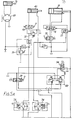
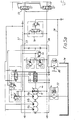
- One example of a suitable closed circuit system for the machine will now be described with reference to Figure 5.
- the main pump 11 is a variable swashplate type and includes an integral boost pump lla and two auxilliary gear pumps llb and llc.
- the pumps lla, llb and llc draw fluid from the 45 gallon oil storage tank 14.
- a suction filter 51 is provided in the line to boost pump lla.
- the main output lines from the pump 11 are indicated under references 55 and 56.
- Line 57 is a control line, as will be explained below.
- valves 52 and 53 which are mechanically inter-linked so that they cannot both be selected at the same time.
- Valves 52 and 53 are also mechanically inter-linked with control valves 54 and 58 which take fluid under control pressure from line 57.
- Control valve 54 in turn controls pump control valves 59 and 60 in such a way that, when the roller drive is connected, the valve 59 is inoperative while the valve 60 is operative and, when the road wheel drive is connected, the valve 59 is operative while the valve 60 is inoperative.
- the valve 59 is the forward/neutral/reverse selector for the road wheel drive; the valve 60 provides infinitely variable control of the speed of rotation of the rollers from 0 to 183 R.P.M., forward or reverse.
- the axle drive speed is controlled directly by a foot throttle control on the prime mover (not shown).
- the control valve 58 applies pressure to wheel brake cylinders to lock the road wheels when the roller drive is connected.
- roller drive When roller drive is selected, oil is diverted along line 62 into a rotary flow divider 61 which splits the flow equally into four and thence into the individual roller drive motors 13.
- the flow divider 61 acts to prevent freewheeling of the unloaded rollers as a tube is inserted since this would otherwise lead to loss of traction of the infeed rollers.
- the oil returns to the valve 52 via a line 64.
- Relief valve 63 protects the motors 13 from pressure intensification by the flow divider.
- axle drive When axle drive is selected, oil is directed along line 65 to a pair of axle drive motors 12 (one for each wheel) via a motion control and lock valve 66.
- the valve 66 is controlled by fluid along line 67 and acts to.prevent vehicle runaway on slopes by providing a measure of hydrostatic braking.
- the valve 66 also acts to provide differential wheel motion, thus eliminating the necessity for a mechanical differential.
- the safety roller 45 and steering are both driven by the pump section llc which takes oil direct from the storage tank 14 via pressure filter 73.
- the safety roller ram 45 is'selected by valve 68 and protected by pressure relief valve 72.
- the right-hand end of the safety roller cylinder 45 is supplied with a constant low pressure pilot supply derived from control line 57, while the left-hand (piston) end of the cylinder is fed with line pressure via valve 68.
- the steering mechanism comprises an hydraulic steering valve 69 and cylinder 70 which acts on the wheel steering mechanism.
- the steering valve 69 receives oil through a priority valve 71 and incorporates a blocked port arrangement to prevent steering deviation.
- the hydraulic ram 19, forming part of the pre-straightener 16 is driven by pump section llb, taking oil from tank 14 via a pressure filter 74.
- the ram 19 is activated by valve 75 and, in operation, cycles backwards and forwards due to the cyclic action of valves 76 and 77.
- a valve 78 in the main pump circuit acts to divert oil from the main flow to. flush the pump casing via line 79 to act as a pump coolant. After cooling the pump, the oil passes through the oil cooler unit on the prime mover, shown under reference 80, together with leakage oil from the roller motors 13.
- a valve 81 across the main pump lines to the road wheel motors enables the wheel drive circuit to be vented so that the vehicle may be towed in the event of mechanical failure.
Landscapes
- Engineering & Computer Science (AREA)
- Mechanical Engineering (AREA)
- Road Paving Machines (AREA)
- Apparatuses For Bulk Treatment Of Fruits And Vegetables And Apparatuses For Preparing Feeds (AREA)
- Catching Or Destruction (AREA)
- Jellies, Jams, And Syrups (AREA)
Applications Claiming Priority (2)
| Application Number | Priority Date | Filing Date | Title |
|---|---|---|---|
| GB8036148 | 1980-11-11 | ||
| GB8036148 | 1980-11-11 |
Publications (2)
| Publication Number | Publication Date |
|---|---|
| EP0051950A2 true EP0051950A2 (de) | 1982-05-19 |
| EP0051950A3 EP0051950A3 (de) | 1982-06-16 |
Family
ID=10517219
Family Applications (1)
| Application Number | Title | Priority Date | Filing Date |
|---|---|---|---|
| EP81305037A Withdrawn EP0051950A3 (de) | 1980-11-11 | 1981-10-26 | Fahrbare Richtmaschine für Rohre |
Country Status (10)
| Country | Link |
|---|---|
| EP (1) | EP0051950A3 (de) |
| JP (1) | JPS57154326A (de) |
| AU (1) | AU7734881A (de) |
| BR (1) | BR8107287A (de) |
| DK (1) | DK492181A (de) |
| ES (1) | ES8403337A1 (de) |
| FI (1) | FI813474L (de) |
| GR (1) | GR74681B (de) |
| NO (1) | NO813639L (de) |
| PL (1) | PL233712A1 (de) |
Cited By (4)
| Publication number | Priority date | Publication date | Assignee | Title |
|---|---|---|---|---|
| CN102527780A (zh) * | 2012-03-05 | 2012-07-04 | 常熟市非凡金属制品有限公司 | 钢坯淬火矫直一体机 |
| WO2012153129A1 (en) * | 2011-05-09 | 2012-11-15 | Matthew Murphy | A pipe straightening apparatus and a method of straightening a pipe |
| CN103658239A (zh) * | 2013-11-30 | 2014-03-26 | 大连市旅顺钢模板修复机设备厂有限公司 | 一种校正直管机 |
| TWI565542B (zh) * | 2016-07-21 | 2017-01-11 | jia-rong Lin | Tube device |
Families Citing this family (1)
| Publication number | Priority date | Publication date | Assignee | Title |
|---|---|---|---|---|
| CN113369338B (zh) * | 2021-04-28 | 2023-04-18 | 中军建工集团(安徽)有限公司 | 一种建筑用高强度抗震钢材制备设备 |
Family Cites Families (4)
| Publication number | Priority date | Publication date | Assignee | Title |
|---|---|---|---|---|
| US3540251A (en) * | 1968-06-14 | 1970-11-17 | Gulf & Western Ind Prod Co | Cross-roll straightener drive assembly |
| US3604236A (en) * | 1968-08-30 | 1971-09-14 | Gulf & Western Ind Prod Co | Cross roll adjusting and locking means |
| US3706215A (en) * | 1971-02-19 | 1972-12-19 | Herbert D Horton | Rotary pipe straightener |
| CA1064806A (en) * | 1976-08-23 | 1979-10-23 | International Tool And Supply Co. Inc. | Heavy duty mobile pipe straightening machine of relatively light-weight construction |
-
1981
- 1981-10-26 EP EP81305037A patent/EP0051950A3/de not_active Withdrawn
- 1981-10-26 GR GR66364A patent/GR74681B/el unknown
- 1981-10-28 NO NO813639A patent/NO813639L/no unknown
- 1981-11-04 FI FI813474A patent/FI813474L/fi not_active Application Discontinuation
- 1981-11-06 PL PL23371281A patent/PL233712A1/xx unknown
- 1981-11-06 DK DK492181A patent/DK492181A/da unknown
- 1981-11-10 AU AU77348/81A patent/AU7734881A/en not_active Abandoned
- 1981-11-10 ES ES506966A patent/ES8403337A1/es not_active Expired
- 1981-11-10 BR BR8107287A patent/BR8107287A/pt unknown
- 1981-11-11 JP JP56179886A patent/JPS57154326A/ja active Pending
Cited By (7)
| Publication number | Priority date | Publication date | Assignee | Title |
|---|---|---|---|---|
| WO2012153129A1 (en) * | 2011-05-09 | 2012-11-15 | Matthew Murphy | A pipe straightening apparatus and a method of straightening a pipe |
| US20140150512A1 (en) * | 2011-05-09 | 2014-06-05 | Matthew Murphy | Pipe straightening apparatus and a method of straightening a pipe |
| US9751121B2 (en) | 2011-05-09 | 2017-09-05 | Matthew Murphy | Pipe straightening apparatus and a method of straightening a pipe |
| CN102527780A (zh) * | 2012-03-05 | 2012-07-04 | 常熟市非凡金属制品有限公司 | 钢坯淬火矫直一体机 |
| CN103658239A (zh) * | 2013-11-30 | 2014-03-26 | 大连市旅顺钢模板修复机设备厂有限公司 | 一种校正直管机 |
| CN103658239B (zh) * | 2013-11-30 | 2015-12-09 | 大连市旅顺钢模板修复机设备厂有限公司 | 一种校正直管机 |
| TWI565542B (zh) * | 2016-07-21 | 2017-01-11 | jia-rong Lin | Tube device |
Also Published As
| Publication number | Publication date |
|---|---|
| JPS57154326A (en) | 1982-09-24 |
| GR74681B (de) | 1984-07-03 |
| AU7734881A (en) | 1982-05-20 |
| NO813639L (no) | 1982-05-12 |
| DK492181A (da) | 1982-05-12 |
| EP0051950A3 (de) | 1982-06-16 |
| ES506966A0 (es) | 1983-08-01 |
| FI813474A7 (fi) | 1982-05-12 |
| ES8403337A1 (es) | 1983-08-01 |
| BR8107287A (pt) | 1982-08-03 |
| PL233712A1 (de) | 1982-07-05 |
| FI813474L (fi) | 1982-05-12 |
Similar Documents
| Publication | Publication Date | Title |
|---|---|---|
| US3888542A (en) | Road planing machines | |
| US4886142A (en) | Hydraulic four-wheel drive system | |
| US4322899A (en) | Self-propelled, non-riding trenching machine with a steering mechanism | |
| US6862872B2 (en) | Power mower with riding platform for supporting standing-operator | |
| US5197784A (en) | Apparatus for removing floor covering | |
| WO2014059480A1 (en) | Vehicle for line marking | |
| DE602004003581T3 (de) | Gabelstapler mit einem einzelnen vorderrad | |
| EP0051950A2 (de) | Fahrbare Richtmaschine für Rohre | |
| US5373877A (en) | Log splitter | |
| CA1042318A (en) | Device for cross-cutting tree trunks | |
| US2990900A (en) | Turning-control device for a track-laying vehicle | |
| US3938401A (en) | Two-speed motor control for dual hydrostatic transmissions | |
| JPS5920177A (ja) | 泡沫濃縮液供給システム | |
| US20030024371A1 (en) | Portable bandsaw mill | |
| US4516808A (en) | Pavement grinding apparatus | |
| EP0050319A2 (de) | Steuerungseinrichtung für den Druckerzeuger in einem Höchstdruck-Kreis | |
| US3547492A (en) | Pavement cutting apparatus | |
| US5133236A (en) | Tire cutting tool | |
| US3506174A (en) | Apparatus for handling an elongate member | |
| US8341955B2 (en) | Hydraulic drive and control system for pumps using a charge pump | |
| DE102005059351A1 (de) | Hydrauliksystem für eine selbstfahrende Erntemaschine | |
| US20060039756A1 (en) | Self-propelled device for milling road surfaces | |
| US6098738A (en) | Hydraulic drive system for a vehicle | |
| US20250178682A1 (en) | Track tensioning system | |
| US2755625A (en) | Hydraulic steering mechanism for tractors |
Legal Events
| Date | Code | Title | Description |
|---|---|---|---|
| PUAI | Public reference made under article 153(3) epc to a published international application that has entered the european phase |
Free format text: ORIGINAL CODE: 0009012 |
|
| PUAL | Search report despatched |
Free format text: ORIGINAL CODE: 0009013 |
|
| AK | Designated contracting states |
Designated state(s): AT BE CH DE FR GB IT LU NL SE |
|
| AK | Designated contracting states |
Designated state(s): AT BE CH DE FR GB IT LU NL SE |
|
| STAA | Information on the status of an ep patent application or granted ep patent |
Free format text: STATUS: THE APPLICATION IS DEEMED TO BE WITHDRAWN |
|
| 18D | Application deemed to be withdrawn |
Effective date: 19830526 |
|
| RIN1 | Information on inventor provided before grant (corrected) |
Inventor name: SCRIVEN, CYRIL EDWARD |