EP0051772A2 - Bedienungshebel mit Sicherheitseinrichtung für Steuerventile mit handbetätigtem gleitenden Verteiler, angewandt in hydraulisch betätigten Hebetriebwerken und Förderaggregaten - Google Patents
Bedienungshebel mit Sicherheitseinrichtung für Steuerventile mit handbetätigtem gleitenden Verteiler, angewandt in hydraulisch betätigten Hebetriebwerken und Förderaggregaten Download PDFInfo
- Publication number
- EP0051772A2 EP0051772A2 EP81108758A EP81108758A EP0051772A2 EP 0051772 A2 EP0051772 A2 EP 0051772A2 EP 81108758 A EP81108758 A EP 81108758A EP 81108758 A EP81108758 A EP 81108758A EP 0051772 A2 EP0051772 A2 EP 0051772A2
- Authority
- EP
- European Patent Office
- Prior art keywords
- pivot
- yoke
- lever
- control valve
- operated
- Prior art date
- Legal status (The legal status is an assumption and is not a legal conclusion. Google has not performed a legal analysis and makes no representation as to the accuracy of the status listed.)
- Granted
Links
Images

Classifications
-
- F—MECHANICAL ENGINEERING; LIGHTING; HEATING; WEAPONS; BLASTING
- F16—ENGINEERING ELEMENTS AND UNITS; GENERAL MEASURES FOR PRODUCING AND MAINTAINING EFFECTIVE FUNCTIONING OF MACHINES OR INSTALLATIONS; THERMAL INSULATION IN GENERAL
- F16H—GEARING
- F16H61/00—Control functions within control units of change-speed- or reversing-gearings for conveying rotary motion ; Control of exclusively fluid gearing, friction gearing, gearings with endless flexible members or other particular types of gearing
- F16H61/18—Preventing unintentional or unsafe shift, e.g. preventing manual shift from highest gear to reverse gear
-
- G—PHYSICS
- G05—CONTROLLING; REGULATING
- G05G—CONTROL DEVICES OR SYSTEMS INSOFAR AS CHARACTERISED BY MECHANICAL FEATURES ONLY
- G05G5/00—Means for preventing, limiting or returning the movements of parts of a control mechanism, e.g. locking controlling member
- G05G5/02—Means preventing undesired movements of a controlling member which can be moved in two or more separate steps or ways, e.g. restricting to a stepwise movement or to a particular sequence of movements
Definitions
- the invention relates to an operating lever, incorporating a safety device, for control valves of manually-operated sliding-spool type used in hydraulically-operated lifting gear and conveyor systems -that is, a stick on which to lay hold and by means of-which manipulate the control valve which operates machinery, or parts thereof, employed in the lifting of loads or the moving about of materials by internal industrial conveyor plant: the inclusion of the safety device in the lever assembly being intended more especially to guard against untimely function of machinery arising out of unwarranted operation by unskilled personnel Current technology makes no provision for such a safety device incorporated into the operating lever mechanism, - only a shield for protection of the lever itself against damage by accidental impact.
- the aforesaid technology is susceptible to further improvement with regard to the fact that a simple shield affords insufficient protection in itself against the possibility of the lever's being manipulated by a child, or other inexpert individual, occasioning unwanted operation of machinery or parts thereof and consequent risk of serious danger to persons and property. From the above outline one may discern the necessity for a solution to the technical problem posed by a lever incapable of operation by a child or other inexpert individual -that is, a lever corresponding to recently prescribed accident prevention standards.
- the invention described herein resolves.
- the advantage provided by the invention is that of having created a smple and effective safety device which will prevent the lever's being moved in the accepted direction of operation,. in the event of its being laid hold on by a child or other inexpert individual.
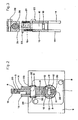
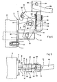
- 1 denotes a plate connecting fixture 3 to the valve body 2, fixture 3 furnished with a bracket 4 extending into a further portion 5 provided with a slot denoted by 6; 7 denotes centres located in plate 1 for fixing thereof to pump body 2 by means of inserting and tightening bolts 8; 9 denotes an aperture in plate 1 through which the piston 10 of control valve 2 is destined to pass; 11 denotes the shank of piston 10, furnished with a through hole by means of which to accomodate a pivot provided with two prismatic extremities 12 forming sliding pairs with relative slots 13 located in a yoke 14 protruding forth from bush 15, the latter accommodating a pivot 16 coupled in rotation therewith and retained axially therein by means of a tangientally located pin 17 engaging an undercut in said pivot 16; 19 denotes a radial arm extending forth from pivot 16, at the extremity of which arm a tooth 20 is affixed, this being disposed laterally thereon and designed to seek out and mate with slot 6 in
- the invention functions in the following manner: from the locked position (fig 1) the operator caused the device to pass into one of the working positions (fig 2) by manipulating lever shaft 26 so as to produce its rotation around pivot 16 thereby soliciting torsion spring 21, thus occasioning lateral disengagement of tooth 20 from slot 6 in bracket portion 5; this accomplished, the operator then works on lever 26, causing its rotation around transverse pivot 28 in the normal fashion thus making piston 10 to stroke in one direction or the other in order to procure the flow of hydraulic fluid through the body of chamber 2, Angular displacement of lever 26 in the traditional direction produces a corresponding angular movement in arm 19 and yoke 14, which in turn causes a related movement between shank 11, pivot extremities 12 and slots 13, and ultimately pivot 29.
Landscapes
- Engineering & Computer Science (AREA)
- General Engineering & Computer Science (AREA)
- Mechanical Engineering (AREA)
- Physics & Mathematics (AREA)
- General Physics & Mathematics (AREA)
- Automation & Control Theory (AREA)
- Mechanically-Actuated Valves (AREA)
- Mechanical Control Devices (AREA)
Applications Claiming Priority (2)
| Application Number | Priority Date | Filing Date | Title |
|---|---|---|---|
| ITMO1980U29050U IT8029050U1 (it) | 1980-11-12 | 1980-11-12 | Leva di azionamento del distributore oleoidraulico a cassetto con dispositivo di sicurezza, nelle macchine per sollevamento e per trasporti interni |
| IT2905080U | 1980-11-12 |
Publications (3)
| Publication Number | Publication Date |
|---|---|
| EP0051772A2 true EP0051772A2 (de) | 1982-05-19 |
| EP0051772A3 EP0051772A3 (en) | 1983-04-27 |
| EP0051772B1 EP0051772B1 (de) | 1986-07-23 |
Family
ID=11225978
Family Applications (1)
| Application Number | Title | Priority Date | Filing Date |
|---|---|---|---|
| EP81108758A Expired EP0051772B1 (de) | 1980-11-12 | 1981-10-22 | Bedienungshebel mit Sicherheitseinrichtung für Steuerventile mit handbetätigtem gleitenden Verteiler, angewandt in hydraulisch betätigten Hebetriebwerken und Förderaggregaten |
Country Status (3)
| Country | Link |
|---|---|
| EP (1) | EP0051772B1 (de) |
| DE (1) | DE3174985D1 (de) |
| IT (1) | IT8029050U1 (de) |
Cited By (1)
| Publication number | Priority date | Publication date | Assignee | Title |
|---|---|---|---|---|
| GB2144521A (en) * | 1983-08-03 | 1985-03-06 | Ideal Standard | Single-lever sanitary water valve |
Family Cites Families (4)
| Publication number | Priority date | Publication date | Assignee | Title |
|---|---|---|---|---|
| US2512312A (en) * | 1948-04-05 | 1950-06-20 | Bendix Aviat Corp | Lever handle detent and release |
| GB949250A (en) * | 1961-09-29 | 1964-02-12 | Short Brothers & Harland Ltd | Improved locking means for a pivoted selector lever |
| DE2611628A1 (de) * | 1976-03-19 | 1977-09-22 | Bosch Gmbh Robert | Betaetigungseinrichtung fuer wegeventile |
| US4229993A (en) * | 1978-04-07 | 1980-10-28 | Andresen Herman J | Actuating device |
-
1980
- 1980-11-12 IT ITMO1980U29050U patent/IT8029050U1/it unknown
-
1981
- 1981-10-22 DE DE8181108758T patent/DE3174985D1/de not_active Expired
- 1981-10-22 EP EP81108758A patent/EP0051772B1/de not_active Expired
Cited By (1)
| Publication number | Priority date | Publication date | Assignee | Title |
|---|---|---|---|---|
| GB2144521A (en) * | 1983-08-03 | 1985-03-06 | Ideal Standard | Single-lever sanitary water valve |
Also Published As
| Publication number | Publication date |
|---|---|
| EP0051772B1 (de) | 1986-07-23 |
| IT8029050U1 (it) | 1982-05-12 |
| IT8029050V0 (it) | 1980-11-12 |
| EP0051772A3 (en) | 1983-04-27 |
| DE3174985D1 (en) | 1986-08-28 |
Similar Documents
| Publication | Publication Date | Title |
|---|---|---|
| EP0133981B1 (de) | Mechanische Überlastungssicherung | |
| EP0085498B1 (de) | Gehäuseaufbau für fluidbetätigte Schaltstangen | |
| DE69016868T2 (de) | Hydraulisches Getriebe für ein Motorfahrzeug. | |
| NZ196479A (en) | Friction pivot joint for stay | |
| DE3510471C2 (de) | ||
| EP2050911A2 (de) | Angetriebener Beschlag | |
| DE4101705C2 (de) | Handgeführte Elektrowerkzeugmaschine mit einer Einrichtung zum schnellen Stillsetzen des Werkzeuges | |
| EP3073155B1 (de) | Vorrichtung zur hemmung der auswahl einer oder mehrerer betriebspositionen eines auswahlelements eines automatisch betätigten getriebes, zum beispiel eine parkstellung | |
| EP4448881B1 (de) | Schnellkupplung zum lösbaren verbinden eines werkzeugs mit einem bewegungsarm, insbesondere für erdbewegungsmaschinen und dergleichen und schaufelanordnung mit einer solchen schnellkupplung | |
| EP0051772A2 (de) | Bedienungshebel mit Sicherheitseinrichtung für Steuerventile mit handbetätigtem gleitenden Verteiler, angewandt in hydraulisch betätigten Hebetriebwerken und Förderaggregaten | |
| DE2131393A1 (de) | Hilfskraftgesteuerte Kupplung | |
| EP3687725A1 (de) | Kettensägensystem | |
| DE19929833A1 (de) | Kupplung für Bohrgerät | |
| DE3815245A1 (de) | Sicherheitseinrichtung an einer handwerkzeugmaschine | |
| EP2681018B1 (de) | Werkzeugmaschinensystem | |
| CN107444624B (zh) | 飞机起落架上的可锁轮致动器解离合系统 | |
| EP3536862B1 (de) | Schnellwechsler | |
| GB2162479A (en) | Steerable aircraft landing gear | |
| DE2326597C3 (de) | Überlastschutzeinrichtung für die Antriebswinde einer Gewinnungs-Schrämmaschine | |
| EP1106854B1 (de) | Überlastkupplung | |
| DE2312636B2 (de) | Riementrieb für elektromotorisch betriebene Maschinen, insbesondere Haushaltsgeräte und Bodenbearbeitungsmaschinen | |
| DE4309623A1 (de) | Getriebebaugruppe für Arbeitsfahrzeuge | |
| EP1252807B1 (de) | Kuppelgestell für landwirtschaftliche Maschine | |
| KR850002278Y1 (ko) | 모심는 장치 | |
| DE704585C (de) | Fahrrad mit Hilfsmotorantrieb |
Legal Events
| Date | Code | Title | Description |
|---|---|---|---|
| PUAI | Public reference made under article 153(3) epc to a published international application that has entered the european phase |
Free format text: ORIGINAL CODE: 0009012 |
|
| AK | Designated contracting states |
Designated state(s): DE FR GB |
|
| PUAL | Search report despatched |
Free format text: ORIGINAL CODE: 0009013 |
|
| 17P | Request for examination filed |
Effective date: 19821227 |
|
| AK | Designated contracting states |
Designated state(s): DE FR GB |
|
| GRAA | (expected) grant |
Free format text: ORIGINAL CODE: 0009210 |
|
| AK | Designated contracting states |
Kind code of ref document: B1 Designated state(s): DE FR GB |
|
| REF | Corresponds to: |
Ref document number: 3174985 Country of ref document: DE Date of ref document: 19860828 |
|
| ET | Fr: translation filed | ||
| PLBE | No opposition filed within time limit |
Free format text: ORIGINAL CODE: 0009261 |
|
| STAA | Information on the status of an ep patent application or granted ep patent |
Free format text: STATUS: NO OPPOSITION FILED WITHIN TIME LIMIT |
|
| 26N | No opposition filed | ||
| PGFP | Annual fee paid to national office [announced via postgrant information from national office to epo] |
Ref country code: GB Payment date: 19900907 Year of fee payment: 10 |
|
| PGFP | Annual fee paid to national office [announced via postgrant information from national office to epo] |
Ref country code: FR Payment date: 19901022 Year of fee payment: 10 |
|
| PGFP | Annual fee paid to national office [announced via postgrant information from national office to epo] |
Ref country code: DE Payment date: 19901229 Year of fee payment: 10 |
|
| PG25 | Lapsed in a contracting state [announced via postgrant information from national office to epo] |
Ref country code: GB Effective date: 19911022 |
|
| GBPC | Gb: european patent ceased through non-payment of renewal fee | ||
| PG25 | Lapsed in a contracting state [announced via postgrant information from national office to epo] |
Ref country code: FR Effective date: 19920630 |
|
| PG25 | Lapsed in a contracting state [announced via postgrant information from national office to epo] |
Ref country code: DE Effective date: 19920701 |
|
| REG | Reference to a national code |
Ref country code: FR Ref legal event code: ST |