EP0051562B1 - Case for a watch to be worn next to the body - Google Patents
Case for a watch to be worn next to the body Download PDFInfo
- Publication number
- EP0051562B1 EP0051562B1 EP81810419A EP81810419A EP0051562B1 EP 0051562 B1 EP0051562 B1 EP 0051562B1 EP 81810419 A EP81810419 A EP 81810419A EP 81810419 A EP81810419 A EP 81810419A EP 0051562 B1 EP0051562 B1 EP 0051562B1
- Authority
- EP
- European Patent Office
- Prior art keywords
- casing
- timepiece
- watch
- spring limb
- limb portion
- Prior art date
- Legal status (The legal status is an assumption and is not a legal conclusion. Google has not performed a legal analysis and makes no representation as to the accuracy of the status listed.)
- Expired
Links
Images
Classifications
-
- G—PHYSICS
- G04—HOROLOGY
- G04B—MECHANICALLY-DRIVEN CLOCKS OR WATCHES; MECHANICAL PARTS OF CLOCKS OR WATCHES IN GENERAL; TIME PIECES USING THE POSITION OF THE SUN, MOON OR STARS
- G04B37/00—Cases
- G04B37/14—Suspending devices, supports or stands for time-pieces insofar as they form part of the case
- G04B37/1486—Arrangements for fixing to a bracelet
Definitions
- the invention relates to a housing for a watch to be worn on the body, with at least one fastening tongue which is plugged from the top of the housing onto a fastening tongue arranged laterally on the circumferential area of the watch housing and is secured in position by means of mutually interlocking formations transversely to the plug-on direction, furthermore with a spring bar for a support member for arranging the watch on the body (bracelet, collar, necklace), which is removably mounted in an end region of the connecting body facing away from the watch case between two lower side walls of the same.
- Such connecting bodies can be made decorative and can also be replaced. This takes into account the desire for individuality with regard to jewelry and fashion watches with minimal tool costs. Only one housing tool is required for various design variants of a watch type with a housing manufactured by injection molding or pressing, and only different tools or tool inserts need to be produced for the small, differently designed push-on connecting bodies.
- a watch case according to the preamble of claim 1 is already known (Swiss Patent No. 318 900), in which the position of the connecting body is created without the use of screwing means.
- This solution provides an arched leaf spring which is supported in a groove and which is intended to bring about a latching action during the plugging-on process. Because of the limited space and the high precision required as a result, this proposal can hardly be implemented in a functional manner at realistic costs.
- the invention solves the problem of creating a watch case in which the position of the connecting body is secured against its push-on direction without additional organs and without requiring additional space during the assembly process which is required anyway. It is that. that the end region of the fastening tongue facing away from the watch case - as seen in the housing section perpendicular to the spring bar - extends at a radial distance to beyond the spring bar.
- the watch case consists of the middle section 1 and the base 2.
- the glass is labeled 3.
- Two diametrically opposed, radially outwardly projecting fastening tongues la T-shaped plan are formed on the circumference of the middle housing part 1.
- the T-crossbeams 1b are delimited by arc-shaped surfaces 1d, as a result of which the tongues 1a taper conically towards their ends facing away from the watch case.
- the connecting bodies 4 are designed as push-on caps.
- a fastening means for the bracelet 5 designed as a bracelet telescopic resilient spring webs 6 are used, the ends of which rest in blind holes 4a of the side walls 4b of the push-on caps 4.
- a slot 4d which is open at the bottom.
- the distance between the spring bars 6 and the surfaces 1d of the fastening tongues 1a running concentrically to these is selected such that that the corresponding areas of the loops 5a lie against the surfaces mentioned.
- the fastening of the bracelet loops 5a which is required anyway, eliminates the need for additional means and requires a special operation to secure the position of the push-on caps 4 against their push-on direction.
- the connecting body 4 is formed by receiving the T-shaped fastening tongue 1a in the opposite interior 4e of the connecting body 4 transversely to its push-on direction secured position. If the mutual intermeshing were to be accomplished by a different training of the same kind, and the fastening tongue was provided with a bore and the connection body configured as desired was to be engaged in the aforementioned bore with a projection formed on the underside thereof, this would also ensure the mutual securing of the position transversely to the direction of attachment of the Connection body ensured. In this regard, there are various training and design options.
- Fig. 8 is also indicated by dash-dotted lines that a one-piece bracelet 5 'can also run between the two spring bars 6 on the back of the housing.
- a short loop can first be set by means of the spring bar 6 in the manner shown, through which then z. B. a chain or collar is passed through.
- a collar-like support member can be attached directly.
- a housing type is to be used both for a wristwatch and as a pendulum clock, there are several options for conclusively securing the push-on cap of the fastening device not used in the latter type of use.
- the corresponding spring bar is made thicker in diameter or surrounded by a sleeve. Their cross section can be designed so that the free space surrounding the spring bar 6 of the push-on cap is completely filled in an aesthetic manner.
Abstract
Description
Die Erfindung bezieht sich auf ein Gehäuse für eine am Körper zu tragende Uhr, mit wenigstens einem von der Gehäuseoberseite her auf eine seitlich am Umfangsbereich des Uhrgehäuses angeordneten Befestigungszunge aufgesteckten und durch gegengleiche ineinandergreifende Anformungen quer zur Aufsteckrichtung lagegesicherten, auswechselbaren Verbindungskörper, weiterhin mit einem Federsteg für ein der Anordnung der Uhr am Körper dienendes Tragorgan (Armband, Halsband, Halskette), welcher in einem dem Uhrgehäuse abgewandten Endbereich des Verbindungskörpers zwischen zwei unterseitigen Seitenwandungen desselben demontierbar gelagert ist.The invention relates to a housing for a watch to be worn on the body, with at least one fastening tongue which is plugged from the top of the housing onto a fastening tongue arranged laterally on the circumferential area of the watch housing and is secured in position by means of mutually interlocking formations transversely to the plug-on direction, furthermore with a spring bar for a support member for arranging the watch on the body (bracelet, collar, necklace), which is removably mounted in an end region of the connecting body facing away from the watch case between two lower side walls of the same.
Solche Verbindungskörper lassen sich dekorativ gestalten und zudem auswechseln. Dadurch ist dem in Bezug auf Schmuck- und Modeuhren bestehenden Wunsch nach Individualität bei minimalem Werkzeugkostenaufwand Rechnung getragen. Für verschiedene Gestaltungsvarianten eines Uhrentyps mit im Spritz- oder Pressverfahren hergestelltem Gehäuse ist nur ein Gehäusewerkzeug erforderlich, und nur für die kleinen, unterschiedlich gestalteten Aufsteck-Verbindungskörper sind verschiedene Werkzeuge bzw. Werkzeugeinsätze anzufertigen.Such connecting bodies can be made decorative and can also be replaced. This takes into account the desire for individuality with regard to jewelry and fashion watches with minimal tool costs. Only one housing tool is required for various design variants of a watch type with a housing manufactured by injection molding or pressing, and only different tools or tool inserts need to be produced for the small, differently designed push-on connecting bodies.
Ein besonderes Problem stellt jedoch die Lagesicherung des Verbindungskörpers entgegen seiner Aufsteckrichtung dar. Eine diesbezügliche Anwendung von Schraubmitteln ist sehr kostenaufwendig und hebt den Vorteil der Auswechselbarkeit wieder auf.A particular problem, however, is the securing of the position of the connecting body against its plug-in direction. The use of screwing means in this regard is very expensive and removes the advantage of being exchangeable.
Es ist bereits ein Uhrgehäuse gemäss dem Oberbegriff des Anspruchs 1 bekannt (Schweizer Patent Nr. 318 900), bei dem sich die Lagesicherung des Verbindungskörpers unter Verzicht auf Schraubmittel erstellt. Diese Lösung sieht eine in einer Nut lagernde gewölbte Blattfeder vor, welche während des Aufsteckvorgangs eine Verrastung herbeiführen soll. Wegen der beschränkten Platzverhältnisse und der dadurch erforderlichen grossen Präzision ist dieser Vorschlag bei realistischen Kosten kaum funktionstüchtig realisierbar.A watch case according to the preamble of
Ein anderer Lösungsvorschlag (Schweizer Patent Nr. 204 293) besteht darin, in einem das Uhrgehäuse ringförmig umfassenden Verbindungskörper etwa parallel zu dem der Festlegung des Tragorgans (z. B. Armband) dienenden Federsteg einen Stift bzw. Schraubstift vorzusehen, welcher von einer Befestigungszunge des Uhrgehäuses übergriffen wird. Diese Konstruktion ist nicht nur aufwendig, sondern vergrössert den Verbindungskörper in zum Uhrgehäuse radialer Richtung derart, dass sie schon aus diesem Grunde für Damenschmuckuhren unbrauchbar ist.Another proposed solution (Swiss Patent No. 204 293) is to provide a pin or screw pin in a connecting body which surrounds the watch case in a ring shape and approximately parallel to the spring bar serving to fix the supporting element (e.g. bracelet) Watch case is overlapped. This construction is not only complex, but also enlarges the connecting body in the radial direction to the watch case in such a way that for this reason alone it is unusable for women's jewelry watches.
Durch die Erfindung sollen alle genannten Nachteile vermieden werden.All disadvantages mentioned are to be avoided by the invention.
Die Erfindung löst die Aufgabe, ein Uhrgehäuse zu schaffen, bei dem die Lagesicherung des Verbindungskörpers entgegen seiner Aufsteckrichtung ohne zusätzliche Organe und ohne zusätzlichen Platzbedarf beim ohnehin erforderlichen Montagevorgang erfolgt. Sie besteht darin. dass sich der dem Uhrgehäuse abgewandte Endbereich der Befestigungszunge - im senkrecht zum Federsteg geführten Gehäuseschnitt gesehen - mit radialem Abstand bis über den Federsteg erstreckt.The invention solves the problem of creating a watch case in which the position of the connecting body is secured against its push-on direction without additional organs and without requiring additional space during the assembly process which is required anyway. It is that. that the end region of the fastening tongue facing away from the watch case - as seen in the housing section perpendicular to the spring bar - extends at a radial distance to beyond the spring bar.
Die durch die Erfindung erzielten Vorteile bestehen also darin, dass für die Lagesicherung weder zusätzliche Organe noch teure Anformungen wie seitliche Rastnut, Gewindebohrung o. dgl. erforderlich sind. Dadurch lässt sich der Verbindungskörper sehr klein gestalten, was für Damenschmuckuhren von besonderer Bedeutung ist. Die Lösung erfordert weder Fabrikations- noch Montagekosten und ist in keiner Weise störanfällig.The advantages achieved by the invention thus consist in the fact that neither additional organs nor expensive formations such as a lateral locking groove, threaded hole or the like are required for securing the position. This allows the connector body to be made very small, which is of particular importance for women's jewelry watches. The solution requires neither manufacturing nor assembly costs and is in no way prone to failure.
In der Zeichnung ist ein Ausführungsbeispiel der Erfindung dargestellt. Es zeigen :
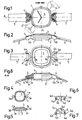
Figur 1 einen Grundriss einer Armbanduhr mit erfindungsgemässem Gehäuse,Figur 2 einen Seitenriss nach Fig. 1,Figur 3 eine bodenseitige Ansicht nach Fig. 1,Figur 4 einen Grundriss des Gehäuses,Figur 5 einen Seitenriss des Gehäuses,Figur 6 einen Seitenriss eines als Aufsteckkappe ausgebildeten Verbindungskörpers (in Richtung auf den die Armbandanschlussstelle aufweisenden äusseren Endbereich),- Figur 7 eine Unteransicht der Aufsteckkappe nach Fig. 6 und
- Figur 8 einen Seitenriss
entsprechend Figur 2 mit teilgeschnittenen Gehäuse (ohne Uhrwerk).
- FIG. 1 shows a floor plan of a wristwatch with a housing according to the invention,
- FIG. 2 shows a side elevation according to FIG. 1,
- FIG. 3 shows a bottom view according to FIG. 1,
- FIG. 4 shows a plan of the housing,
- FIG. 5 shows a side elevation of the housing,
- FIG. 6 shows a side elevation of a connecting body designed as a push-on cap (in the direction of the outer end region having the bracelet connection point),
- 7 shows a bottom view of the push-on cap according to FIGS. 6 and
- Figure 8 is a side elevation corresponding to Figure 2 with a partially cut housing (without clockwork).
Das Uhrgehäuse besteht aus dem Gehäusemittelteil 1 und dem Boden 2. Das Glas ist mit 3 bezeichnet. Am Umfang des gehäusemittelteils 1 sind zwei sich diametral gegenüberliegende, radial nach aussen stehende Befestigungszungen la T-förmigen Grundrisses angeformt. Unterseitig sind die T-Querbalken 1b durch kreisbogenförmige Flächen 1d begrenzt, wodurch sich die Zungen 1a zu ihren dem Uhrgehäuse abgewandten Enden konisch verjüngen.The watch case consists of the
Die Verbindungskörper 4 sind als Aufsteckkappen ausgebildet. Als Befestigungsmittel für das als Armband ausgebildete Tragorgan 5 dienen in bekannter Weise teleskopartig federnd ausgebildete Federstege 6, die mit ihren Enden in Sacklochbohrungen 4a der Seitenwandungen 4b der Aufsteckkappen 4 lagern. In der dem Uhrgehäuse 1, 2 zugekehrten Wandung 4c der Aufsteckkappen 4 befindet sich ein nach unten offener Schlitz 4d.The connecting
Bei demontierten Federstegen 6 werden die Aufsteckkappen 4 von der Gehäuseoberseite her auf die T-förmigen Befestigungszungen 1a aufgesteckt, wobei die T-Längsbalken 1c der Befestigungszungen 1a in die Schlitze 4d gleiten, während die T-Querbalken 1b im Innenraum 4e der Aufsteckkappen 4 Platz finden. Diese sind somit quer zur Aufsteckrichtung lagegesichert. Wie insbesondere aus Fig. 8 zu ersehen ist, ragen die konisch verjüngten T-Querbalken 1b der Befestigungszungen 1a in einem gewissen radialen Abstand bis über die anschliessend eingesetzten, von den Armbandschlaufen 5a umschlungenen Federstege 6. Der Abstand zwischen den Federstegen 6 und den konzentrisch zu diesen verlaufenden Flächen 1d der Befestigungszungen 1a ist so gewählt, dass die entsprechenden Bereiche der Schlaufen 5a gegen die genannten Flächen anliegen. Auf diese Weise erstellt sich durch die ohnehin erforderliche Befestigung der Armbandschlaufen 5a unter Verzicht auf zusätzliche Mittel und einen besonderen Arbeitsvorgang die erforderliche Lagesicherung der Aufsteckkappen 4 entgegen ihrer Aufsteckrichtung.When the
Die T-Form der Befestigungszungen 1a und die Ausbildung der Verbindungskörper 4 als gegengleiche Aufsteckkappen stellen lediglich ein vorteilhaftes Ausführungsbeispiel dar. Bei dieser Lösung wird der Verbindungskörper 4 durch Aufnahme der T-förmigen Befestigungszunge 1a in den gegengleichen Innenraum 4e des Verbindungskörpers 4 quer zu dessen Aufsteckrichtung lagegesichert. Würde man nun das gegenseitige Ineinandergreifen durch eine andere gegengleiche Ausbildung bewerkstelligen, und dabei die Befestigungszunge mit einer Bohrung versehen und den beliebig konfigurieten Verbindungskörper mit einem ihm unterseitig angeformten Vorsprung in die genannte Bohrung eingreifen lassen, so wäre dadurch ebenfalls die gegenseitige Lagesicherung quer zur Aufsteckrichtung des Verbindungskörpers sichergestellt. In dieser Hinsicht sind verschiedene Ausbildungs- und somit Designmöglichkeiten gegeben.The T-shape of the fastening
In Fig. 8 ist noch strichpunktiert angedeutet, dass ein einteiliges Armband 5' auch zwischen den beiden Federstegen 6 gehäuserückseitig verlaufen kann.In Fig. 8 is also indicated by dash-dotted lines that a one-piece bracelet 5 'can also run between the two
Bei einem rechteckigen Uhrgehäuse besteht entsprechend Fig. 1 auch die Möglichkeit, die Verbindungskörper 4' auf einer Gehäusediagonalen anzuordnen.In the case of a rectangular watch case, as shown in FIG. 1, there is also the possibility of arranging the connecting bodies 4 'on a diagonal case.
Ist die Uhr als Pendativ ausgebildet, so kann mittels des Federsteges 6 in der dargestellten Art zunächst eine kurze Schlaufe festgelegt werden, durch die dann z. B. eine Kette oder ein Halsband hindurchgeführt wird. Als Alternative ist jedoch ein halsbandartiges Tragorgan direkt befestigbar.If the watch is designed as a pendulum, a short loop can first be set by means of the
Soll ein Gehäusetyp sowohl für eine Armbanduhr als auch als Pendativuhr verwendet werden, so bestehen mehrere Möglichkeiten, die Aufsteckkappe der bei der letztgenannten Verwendungsart nicht benutzten Befestigungseinrichtung schlüssig zu sichern. So kann z. B. der entsprechende Federsteg im Durchmesser dicker ausgebildet oder von einer Hülse umgeben werden. Deren Querschnitt lässt sich so gestalten, dass der den Federsteg 6 umgebende freie Raum der Aufsteckkappe in ästhetischer Weise völlig ausgefüllt ist.If a housing type is to be used both for a wristwatch and as a pendulum clock, there are several options for conclusively securing the push-on cap of the fastening device not used in the latter type of use. So z. B. the corresponding spring bar is made thicker in diameter or surrounded by a sleeve. Their cross section can be designed so that the free space surrounding the
Claims (4)
Priority Applications (1)
| Application Number | Priority Date | Filing Date | Title |
|---|---|---|---|
| AT81810419T ATE12553T1 (en) | 1980-11-03 | 1981-10-22 | CASE FOR A BODY WEAR WATCH. |
Applications Claiming Priority (2)
| Application Number | Priority Date | Filing Date | Title |
|---|---|---|---|
| CH8142/80 | 1980-11-03 | ||
| CH814280A CH630500B (en) | 1980-11-03 | 1980-11-03 | CASE FOR A WATCH TO BE WEARED ON THE BODY. |
Publications (2)
| Publication Number | Publication Date |
|---|---|
| EP0051562A1 EP0051562A1 (en) | 1982-05-12 |
| EP0051562B1 true EP0051562B1 (en) | 1985-04-03 |
Family
ID=4335788
Family Applications (1)
| Application Number | Title | Priority Date | Filing Date |
|---|---|---|---|
| EP81810419A Expired EP0051562B1 (en) | 1980-11-03 | 1981-10-22 | Case for a watch to be worn next to the body |
Country Status (6)
| Country | Link |
|---|---|
| US (1) | US4466745A (en) |
| EP (1) | EP0051562B1 (en) |
| JP (1) | JPS57122802A (en) |
| AT (1) | ATE12553T1 (en) |
| CH (1) | CH630500B (en) |
| DE (1) | DE3169723D1 (en) |
Cited By (1)
| Publication number | Priority date | Publication date | Assignee | Title |
|---|---|---|---|---|
| CN108786078A (en) * | 2018-06-25 | 2018-11-13 | 深圳市定尔志电子有限公司 | A kind of sport timer wearable device |
Families Citing this family (6)
| Publication number | Priority date | Publication date | Assignee | Title |
|---|---|---|---|---|
| EP0366613A1 (en) * | 1988-10-27 | 1990-05-02 | Mondaine Watch Ltd | Watch-case |
| US20100329084A1 (en) * | 2009-06-30 | 2010-12-30 | Shanker Mo | Clock Having Diverse Ornamental Variations |
| US8480247B2 (en) | 2011-04-27 | 2013-07-09 | Philip B. Fleet | Interchangeable decoration system |
| USD766775S1 (en) * | 2014-01-30 | 2016-09-20 | Glashütter Uhrenbetrieb GmbH | Clasp |
| USD798741S1 (en) * | 2015-09-17 | 2017-10-03 | Graff Diamonds Sa | Watch |
| TWD208143S (en) * | 2019-10-08 | 2020-11-11 | 瑞士商哈利溫士頓公司 | Watch case |
Family Cites Families (8)
| Publication number | Priority date | Publication date | Assignee | Title |
|---|---|---|---|---|
| CH204293A (en) * | 1938-05-04 | 1939-04-30 | Ponti Gennari & Cie | Wristwatch. |
| US2344422A (en) * | 1940-03-04 | 1944-03-14 | Sickinger Helmut | Watchcase |
| CH318900A (en) * | 1955-03-11 | 1957-01-31 | Marthaler Rene | Removable device for fixing the end of a link to a watch case |
| US2775861A (en) * | 1955-10-24 | 1957-01-01 | Bulova Watch Co Inc | Wrist watch bracelet attachment |
| GB933969A (en) * | 1960-10-28 | 1963-08-14 | Theodor Engelhard | Improvements in or relating to strap attachments for wristwatches |
| US3165884A (en) * | 1962-11-14 | 1965-01-19 | Bulova Watch Co Inc | Watch band connector |
| US4231502A (en) * | 1978-08-15 | 1980-11-04 | Stanley Meyerson | Watch bracelet |
| US4266326A (en) * | 1979-08-06 | 1981-05-12 | Hong Lai F | Watchband connector |
-
1980
- 1980-11-03 CH CH814280A patent/CH630500B/en unknown
-
1981
- 1981-10-22 AT AT81810419T patent/ATE12553T1/en not_active IP Right Cessation
- 1981-10-22 EP EP81810419A patent/EP0051562B1/en not_active Expired
- 1981-10-22 DE DE8181810419T patent/DE3169723D1/en not_active Expired
- 1981-11-02 US US06/317,488 patent/US4466745A/en not_active Expired - Fee Related
- 1981-11-02 JP JP56176320A patent/JPS57122802A/en active Pending
Cited By (1)
| Publication number | Priority date | Publication date | Assignee | Title |
|---|---|---|---|---|
| CN108786078A (en) * | 2018-06-25 | 2018-11-13 | 深圳市定尔志电子有限公司 | A kind of sport timer wearable device |
Also Published As
| Publication number | Publication date |
|---|---|
| JPS57122802A (en) | 1982-07-30 |
| DE3169723D1 (en) | 1985-05-09 |
| US4466745A (en) | 1984-08-21 |
| ATE12553T1 (en) | 1985-04-15 |
| CH630500GA3 (en) | 1982-06-30 |
| EP0051562A1 (en) | 1982-05-12 |
| CH630500B (en) |
Similar Documents
| Publication | Publication Date | Title |
|---|---|---|
| EP0051562B1 (en) | Case for a watch to be worn next to the body | |
| DE1936655A1 (en) | Wristwatch with exchangeable central part bezel | |
| DE69938543T2 (en) | Chronograph watch made of precious metal with a hollowed out bezel center part | |
| DE2157187A1 (en) | Wrist watch | |
| DE2813169C2 (en) | Heald frame | |
| EP0736824B1 (en) | Case for a wristwatch | |
| DE1757674B1 (en) | umbrella | |
| EP0639283B1 (en) | Wristwatch | |
| DE7710598U1 (en) | Electric light bulb socket | |
| DE8300471U1 (en) | Wrist watch | |
| DE1055453B (en) | Hidden bracelet connection on watches | |
| CH431669A (en) | Blade contact arrangement | |
| EP3641583B1 (en) | Wristwatch and wrist-strap device for a wristwatch | |
| DE3635529C2 (en) | ||
| WO1997039387A1 (en) | Wrist watch | |
| DE1134850B (en) | Watch strap for hidden strap connection on the watch case | |
| DE3220706A1 (en) | CLOCK | |
| EP0677797B1 (en) | Wrist-watch | |
| DE1903098U (en) | BULB SCREW SOCKET WITH A LOCKING LINK TO SECURE ANTI-ROTATION. | |
| DE4409525A1 (en) | Safety device, esp. for earrings | |
| DE2730930B1 (en) | Waterproof wrist watch with sealed winder aperture - has back and watch glass frame clipped to support frame including sealing rings | |
| DE202007004423U1 (en) | Schmuckband | |
| DE1177078B (en) | Winding crown for watches | |
| AT204305B (en) | Glasses hinge | |
| EP1271269A2 (en) | Watchcase |
Legal Events
| Date | Code | Title | Description |
|---|---|---|---|
| PUAI | Public reference made under article 153(3) epc to a published international application that has entered the european phase |
Free format text: ORIGINAL CODE: 0009012 |
|
| AK | Designated contracting states |
Designated state(s): AT BE DE FR GB IT NL SE |
|
| KL | Correction list |
Free format text: 82/04 TITELBLATT |
|
| 17P | Request for examination filed |
Effective date: 19821015 |
|
| GRAA | (expected) grant |
Free format text: ORIGINAL CODE: 0009210 |
|
| AK | Designated contracting states |
Designated state(s): AT BE DE FR GB IT NL SE |
|
| PG25 | Lapsed in a contracting state [announced via postgrant information from national office to epo] |
Ref country code: NL Effective date: 19850403 Ref country code: IT Free format text: LAPSE BECAUSE OF FAILURE TO SUBMIT A TRANSLATION OF THE DESCRIPTION OR TO PAY THE FEE WITHIN THE PRESCRIBED TIME-LIMIT;WARNING: LAPSES OF ITALIAN PATENTS WITH EFFECTIVE DATE BEFORE 2007 MAY HAVE OCCURRED AT ANY TIME BEFORE 2007. THE CORRECT EFFECTIVE DATE MAY BE DIFFERENT FROM THE ONE RECORDED. Effective date: 19850403 Ref country code: FR Free format text: THE PATENT HAS BEEN ANNULLED BY A DECISION OF A NATIONAL AUTHORITY Effective date: 19850403 Ref country code: BE Effective date: 19850403 |
|
| REF | Corresponds to: |
Ref document number: 12553 Country of ref document: AT Date of ref document: 19850415 Kind code of ref document: T |
|
| PG25 | Lapsed in a contracting state [announced via postgrant information from national office to epo] |
Ref country code: SE Effective date: 19850430 |
|
| REF | Corresponds to: |
Ref document number: 3169723 Country of ref document: DE Date of ref document: 19850509 |
|
| NLV1 | Nl: lapsed or annulled due to failure to fulfill the requirements of art. 29p and 29m of the patents act | ||
| PG25 | Lapsed in a contracting state [announced via postgrant information from national office to epo] |
Ref country code: AT Effective date: 19851022 |
|
| EN | Fr: translation not filed | ||
| PLBE | No opposition filed within time limit |
Free format text: ORIGINAL CODE: 0009261 |
|
| STAA | Information on the status of an ep patent application or granted ep patent |
Free format text: STATUS: NO OPPOSITION FILED WITHIN TIME LIMIT |
|
| 26N | No opposition filed | ||
| GBPC | Gb: european patent ceased through non-payment of renewal fee | ||
| PG25 | Lapsed in a contracting state [announced via postgrant information from national office to epo] |
Ref country code: DE Effective date: 19870701 |
|
| PG25 | Lapsed in a contracting state [announced via postgrant information from national office to epo] |
Ref country code: GB Effective date: 19881118 |