EP0050740B1 - Akkumulator mit Abstandhalter für formstabile Elektrodenplatten - Google Patents
Akkumulator mit Abstandhalter für formstabile Elektrodenplatten Download PDFInfo
- Publication number
- EP0050740B1 EP0050740B1 EP81107521A EP81107521A EP0050740B1 EP 0050740 B1 EP0050740 B1 EP 0050740B1 EP 81107521 A EP81107521 A EP 81107521A EP 81107521 A EP81107521 A EP 81107521A EP 0050740 B1 EP0050740 B1 EP 0050740B1
- Authority
- EP
- European Patent Office
- Prior art keywords
- projections
- storage battery
- electrode plates
- battery cell
- spacer
- Prior art date
- Legal status (The legal status is an assumption and is not a legal conclusion. Google has not performed a legal analysis and makes no representation as to the accuracy of the status listed.)
- Expired
Links
- 125000006850 spacer group Chemical group 0.000 title claims abstract description 23
- 210000004027 cell Anatomy 0.000 claims abstract 7
- 210000002421 cell wall Anatomy 0.000 claims abstract 2
- 239000004698 Polyethylene Substances 0.000 claims description 4
- -1 polyethylene Polymers 0.000 claims description 4
- 229920000573 polyethylene Polymers 0.000 claims description 4
- 239000000463 material Substances 0.000 claims description 3
- 229920000915 polyvinyl chloride Polymers 0.000 claims description 3
- 239000004800 polyvinyl chloride Substances 0.000 claims description 3
- 239000012815 thermoplastic material Substances 0.000 claims 2
- 239000003792 electrolyte Substances 0.000 description 5
- 238000004519 manufacturing process Methods 0.000 description 4
- 230000001771 impaired effect Effects 0.000 description 3
- 238000000034 method Methods 0.000 description 3
- 230000002411 adverse Effects 0.000 description 1
- 238000011161 development Methods 0.000 description 1
- 230000018109 developmental process Effects 0.000 description 1
- 238000007599 discharging Methods 0.000 description 1
- 239000012777 electrically insulating material Substances 0.000 description 1
- 238000003912 environmental pollution Methods 0.000 description 1
- 239000011888 foil Substances 0.000 description 1
- 238000005342 ion exchange Methods 0.000 description 1
- 150000002500 ions Chemical class 0.000 description 1
- 238000012423 maintenance Methods 0.000 description 1
Images

Classifications
-
- H—ELECTRICITY
- H01—ELECTRIC ELEMENTS
- H01M—PROCESSES OR MEANS, e.g. BATTERIES, FOR THE DIRECT CONVERSION OF CHEMICAL ENERGY INTO ELECTRICAL ENERGY
- H01M10/00—Secondary cells; Manufacture thereof
- H01M10/06—Lead-acid accumulators
- H01M10/12—Construction or manufacture
- H01M10/14—Assembling a group of electrodes or separators
-
- Y—GENERAL TAGGING OF NEW TECHNOLOGICAL DEVELOPMENTS; GENERAL TAGGING OF CROSS-SECTIONAL TECHNOLOGIES SPANNING OVER SEVERAL SECTIONS OF THE IPC; TECHNICAL SUBJECTS COVERED BY FORMER USPC CROSS-REFERENCE ART COLLECTIONS [XRACs] AND DIGESTS
- Y02—TECHNOLOGIES OR APPLICATIONS FOR MITIGATION OR ADAPTATION AGAINST CLIMATE CHANGE
- Y02E—REDUCTION OF GREENHOUSE GAS [GHG] EMISSIONS, RELATED TO ENERGY GENERATION, TRANSMISSION OR DISTRIBUTION
- Y02E60/00—Enabling technologies; Technologies with a potential or indirect contribution to GHG emissions mitigation
- Y02E60/10—Energy storage using batteries
-
- Y—GENERAL TAGGING OF NEW TECHNOLOGICAL DEVELOPMENTS; GENERAL TAGGING OF CROSS-SECTIONAL TECHNOLOGIES SPANNING OVER SEVERAL SECTIONS OF THE IPC; TECHNICAL SUBJECTS COVERED BY FORMER USPC CROSS-REFERENCE ART COLLECTIONS [XRACs] AND DIGESTS
- Y02—TECHNOLOGIES OR APPLICATIONS FOR MITIGATION OR ADAPTATION AGAINST CLIMATE CHANGE
- Y02P—CLIMATE CHANGE MITIGATION TECHNOLOGIES IN THE PRODUCTION OR PROCESSING OF GOODS
- Y02P70/00—Climate change mitigation technologies in the production process for final industrial or consumer products
- Y02P70/50—Manufacturing or production processes characterised by the final manufactured product
Definitions
- the invention relates to an accumulator according to the preamble of claim 1.
- spacers are arranged between the electrode plates and must be porous so that the electrolyte can move between opposite electrode plates as freely as possible and without being impaired in its function.
- the manufacturing effort is very high, but the lifespan is limited. Furthermore, it is practically inevitable that the function of the electrolyte, namely the free mobility of ions, is impaired to a certain extent.
- Porous spacers are too expensive for batteries with larger electrode plate spacings and moreover adversely affect the functioning of the electrolyte. So far, therefore, simple intermediate pieces made of electrically insulating material have been arranged between the plates. A large number of such plates were required for each cell and were relatively complex to manufacture and assemble.
- the invention has for its object to form a spacer for dimensionally stable electrode plates of batteries so that it is easier and cheaper to manufacture and assemble and still works reliably.
- the spacer a) consists of an electrically insulating film in which are arranged at predetermined intervals mutually arranged projections, the lateral extent of which corresponds to the distances between adjacent electrode plates, wherein b) a film is arranged in each battery cell on opposite cell inner walls in such a way that the side edges of the associated electrode plates can be arranged between the projections.
- projections can have any shape, they can preferably be box-shaped, but they can also be cylindrical or conical.
- the projections can also have the shape of continuous ribs (from top to bottom) between which the individual electrode plates can be inserted.
- Polyvinyl chloride or preferably polyethylene with a wall thickness of approximately 0.5 mm can be used as the material for the projections.
- the projections can be glued to the flat film or preferably produced or stamped in the deep-drawing process.
- the object of the invention makes it possible for only two foils, which have projections, to be placed in each battery cell, between which the electrode plates can be inserted.
- Such separators or spacers are made of very inexpensive material, the production is very simple; the same applies to the assembly, in which only two such spacers are placed opposite each other in the housing and the electrode plates are arranged between them. The functioning of the electrolyte is not impaired at all, the ion exchange can take place unhindered.
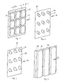
- Fig. 1 est is a spacer 1, shown, which consists of a film 2 and box-shaped projections 3, which are preferably made of polyethylene in the deep-drawing process, but can also be glued or otherwise connected to a flat film.
- the width of the projections 3 is b; it corresponds to the distance between two neighboring electrode grids.
- the height of the projections 3 can be of any type, in extreme cases it can fill the entire height of the battery cell, in which case one speaks of rib-shaped projections (see FIG. 5).
- Rib-shaped projections have the certain disadvantage, however, that the electrolyte is not so freely movable around the edges of the electrode plates (which, however, is not absolutely necessary).
- Fig. 2 shows a three-dimensional schematic representation of three adjacent electrode plates 4, 5 and 6, between which two opposing spacers 1 are provided, each consisting of a film 2 and preferred deep-drawn box-shaped projections 3, with three elongated projections 3 arranged one below the other are.
- the side edges of the electrode grid 4, 5 and 6, with which the projections 3 are in contact, are denoted by 7, 8 and 9.
- Opposite side edges are labeled 10, 11 and 12.
- So-called lugs 13 and 14 protrude upwards, which discharge the current from the same electrode grids through a common connecting line (not shown), and between lugs 13 and 14 a lug 15, which is in contact with the opposite-polarized electrode plate 5.
- FIG 3 shows another exemplary embodiment of a spacer 16, consisting of a film 17 and cylindrical projections 18.
- FIG. 4 shows a further exemplary embodiment of a spacer 19, consisting of a film 20 and conical projections 21.
- FIG. 5 shows a spacer 22, consisting of a film 23 and vertical ribs 24.
Landscapes
- Engineering & Computer Science (AREA)
- Manufacturing & Machinery (AREA)
- Chemical & Material Sciences (AREA)
- Chemical Kinetics & Catalysis (AREA)
- Electrochemistry (AREA)
- General Chemical & Material Sciences (AREA)
- Cell Separators (AREA)
- Secondary Cells (AREA)
Description
- Die Erfindung bezieht sich auf einen Akkumulator nach dem Oberbegriff des Anspruches 1.
- Im allgemeinen werden Abstandhalter zwischen den Elektrodenplatten angeordnet und müssen porös sein, damit der Elektrolyt möglichst frei beweglich und ohne in der Funktion beeinträchtigt zu sein, zwischen gegenüberliegenden Elektrodenplatten wandern kann. Dies macht Abstandhalter oder Separatoren erforderlich, die möglichst porös und dennoch mechanisch stabil sein müssen. Der Herstellungsaufwand ist sehr hoch, dennoch ist die Lebensdauer beschränkt. Darüberhinaus ist es praktisch unvermeidlich, daß die Funktion des Elektrolyten, nämlich die freie lonenbeweglichkeit, in gewissem Maße beeinträchtigt wird.
- Bei geringen Plattenabständen von etwa 1 bis 4 mm ist es in Hinblick auf eine gewisse Flexibilität und mechanische Instabilität sowie eine gewisse variable Elektrodenplattendicke aufgrund des elektrochemischen Prozesses bei der Aufladung und Entladung von Bleiakkumulatoren erforderlich, derartige Abstandhalter zwischen den Elektrodenplatten anzubringen, um einen Kurzschluß zu verhindern.
- Für bestimmte Einsatzzwecke, beispielsweise für eine besonders lange Wartungsfreiheit, Lebensdauer und für besonders hohe Umweltbelastung durch extreme Temperaturunterschiede une extreme Schwankungen der Luftfeuchtigkeit, ist es allerdings erforderlich, Akkumulatoren mit größeren Plattenabständen zu machen. Da bei derartigen Akkumulatoren die Dicke der Elektrodenplatten nicht so sehr ins Gewicht fällt, können derartige Elektrodenplatte dicker und damit formstabiler ausgebildet werden. Durch den größeren Abstand ist auch keine Kurzschlußgefahr mehr gegeben.
- Fur Akkumulatoren mit größeren Elektrodenplattenabständen sind poröse Abstandhalter zu teuer und beeinträchtigen darüberhinaus die Funktionsweise des Elektrolyten nachteilig. Bisher wurden daher einfache Zwischenstücke aus elektrisch isolierendem Material zwischen den Platten angeordnet. Für jede Zelle war eine ganze Anzahl derartiger Platten erforderlich, die verhältnismäßig aufwendig in der Herstellung und in der Montage waren.
- Der Erfindung liegt die Aufgabe zugrunde, einen Abstandhalter für formstabile Elektrodenplatten von Akkumulatoren so auszubilden, daß er einfacher und billiger in der Herstellung und in der Montage ist und dennoch zuverlässig funktioniert.
- Die Aufgabe wird erfindungsgemäß durch die Merkmale des Kennzeichens des Anspruches 1 gelöst. Weitere Ausbildungen der Erfindung sind in den Unteransprüche dargestellt.
- Gemäß der Erfindung besteht der Abstandhalter a) aus einer elektrisch isolierenden Folie, in welche in vorbestimmten Abständen untereinander angeordnete Vorsprünge angeordnet sind, deren seitliche Ausdehnung den Abständen benachbarter Elektrodenplatten entspricht, wobei b) in jeder Akkumulatorzelle an gegenüberliegenden Zelleninnenwänden eine Folie derart angeordnet ist, daß die Seitenkanten der zugehörigen Elektrodenplatten zwischen den Vorsprüngen angeordnet werden können.
- Diese Vorsprünge können beliebige Form aufweisen, sie können vorzugsweise kastenförmig sein, sie können jedoch auch zylinderförmig oder kegelförmig ausgebildet sein. Die Vorsprünge können auch die Form von (von oben nach unten) durchgehenden Rippen aufweisen, zwischen welchen die einzelnen Elektrodenplatten eingeschoben werden können.
- Als Material für die Vorsprünge kann Polyvinylchlorid oder vorzugsweise Polyäthylen mit einer Wandstärke von etwa 0,5 mm verwendet werden. Die Vorsprünge können auf die ebene Folie aufgeklebt oder vorzugsweise im Tiefziehverfahren hergestellt bzw. eingeprägt werden.
- Durch der Erfindungsgegenstand ist es möglich, daß in jede Akkumulatorzelle lediglich zwei Folien, welche Vorsprünge aufweisen, hineingestellt werden, zwischen denen die Elektrodenplatten eingeschoben werden können.
- Derartige Separatoren oder Abstandhalter bestehen aus sehr preiswertem Material, die Herstellung ist denkbar einfach; das Gleiche gilt für die Montage, bei der lediglich zwei derartige Abstandhalter gegenüber in das Gehäuse hineingestellt werden und dazwischen die Elektrodenplatten angeordnet werden. Die Funktionsweise des Elektrolyten wird überhaupt nicht beeinträchtigt, der Ionenaustausch kann ungehindert vonstatten gehen.
- Ausführungsbeispiele der Erfindung sind in der Zeichnung dargestellt. Es zeigt:
- Fig. 1 eine schematische Darstellung eines Abstandhalters mit drei untereinander angeordneten Reihen von Vorsprüngen,
- Fig. 2 eine schematische räumliche Darstellung von drei Elektrodenplatten und zwei gegenüberliegenden Abstandhaltern,
- Fig. 3 eine zylinderförmige Ausbildung von Vorsprüngen auf einem Abstandhalter,
- Fig. 4 eine kegelförmige Ausbildung der Vorsprünge auf einem Abstandhalter,
- Fig. 5 eine rippenförmige Ausbildung der Vorsprünge auf einem Abstandhalter.
- In Fig. 1 est ein Abstandhalter 1, dargestellt, der aus einer Folie 2 und kastenförmigen Vorsprüngen 3 besteht, die vorzugsweise im Tiefziehverfahren aus Polyäthylen hergestellt sind, jedoch auch aufgeklebt oder auf andere Weise mit einer flachen Folie verbunden werden können. Zwischen zwei kastenförmigen Vorsprüngen 3 besteht ein Abstand a, der der Dicke der Elektrodengitter entspricht. Die Breite der Vorsprünge 3 beträgt b; sie entspricht dem Abstand zweier benachbarter Elektrodengitter. Die Höhe der Vorsprünge 3 kann beliebig sein, sie kann im Extremfall die ganze Höhe der Akkumulatorzelle ausfüllen, wobei man dann von rippenförmigen Vorsprüngen spricht (s. dazu Fig. 5). Derartige rippenförmige Vorsprünge haben allerdings den gewissen Nachteil, daß der Elektrolyt um die Kanten der Elektrodenplatten herum nicht so frei beweglich ist (was allerdings auch nicht unbedingt notwendig ist).
- Fig. 2 zeigt eine räumliche schematische Darstellung von drei benachbarten Elektrodenplatten 4, 5 und 6, zwischen denen zwei sich gegenüberliegende Abstandhalter 1 vorgesehen sind, die jeweils aus einer Folie 2 und bevorzugten tiefgezogenen kastenförmigen Vorsprüngen 3 bestehen, wobei jeweils drei längliche Vorsprünge 3 untereinander angeordnet sind. Die Seitenkanten der Elektrodengitter 4, 5 und 6, mit denen die Vorsprünge 3 in Berührung stehen, sind mit 7, 8 und 9 bezeichnet. Gegenüberliegende Seitenkanten sind mit 10, 11 und 12 bezeichnet. Nach oben ragen sogenannte Fahnen 13 und 14, die den Strom von gleichen Elektrodengittern durch eine gemeinsame (nicht gezeigte) Verbindungsleitung nach außen abführen, sowie zwischen den Fahnen 13 und 14 eine Fahne 15, die mit der entgegengesetzt gepolten Elektrodenplatte 5 in Berührung steht.
- In Fig. 3 ist eine anderes Ausführungsbeispiel eines Abstandhalters 16 dargestellt, bestehend aus einer Folie 17 und zylinderförmigen Vorsprüngen 18.
- In Fig. 4 ist ein weiteres Ausführungsbeispiel eines Abstandhalters 19 dargestellt, bestehend aus einer Folie 20 und kegelförmig ausgebildeten Vorsprüngen 21.
- In Fig. 5 ist ein Abstandhalter 22 dargestellt, bestehend aus einer Folie 23 und senkrechten Rippen 24.
Claims (9)
Priority Applications (1)
| Application Number | Priority Date | Filing Date | Title |
|---|---|---|---|
| AT81107521T ATE14810T1 (de) | 1980-10-23 | 1981-09-22 | Akkumulator mit abstandhalter fuer formstabile elektrodenplatten. |
Applications Claiming Priority (2)
| Application Number | Priority Date | Filing Date | Title |
|---|---|---|---|
| DE3040019 | 1980-10-23 | ||
| DE3040019A DE3040019C2 (de) | 1980-10-23 | 1980-10-23 | Abstandhalter für formstabile Elektrodenplatten |
Publications (2)
| Publication Number | Publication Date |
|---|---|
| EP0050740A1 EP0050740A1 (de) | 1982-05-05 |
| EP0050740B1 true EP0050740B1 (de) | 1985-08-07 |
Family
ID=6115034
Family Applications (1)
| Application Number | Title | Priority Date | Filing Date |
|---|---|---|---|
| EP81107521A Expired EP0050740B1 (de) | 1980-10-23 | 1981-09-22 | Akkumulator mit Abstandhalter für formstabile Elektrodenplatten |
Country Status (3)
| Country | Link |
|---|---|
| EP (1) | EP0050740B1 (de) |
| AT (1) | ATE14810T1 (de) |
| DE (1) | DE3040019C2 (de) |
Family Cites Families (5)
| Publication number | Priority date | Publication date | Assignee | Title |
|---|---|---|---|---|
| BE346946A (de) * | ||||
| GB190327399A (en) * | 1903-12-14 | 1904-12-14 | Henry Leitner | Improvements in Means for Separating and Supporting Accumulator Plates. |
| DE563261C (de) * | 1924-11-09 | 1932-11-04 | Meyer Wildermann Dr | Elektrischer Akkumulator |
| LU33720A1 (de) * | 1955-06-01 | |||
| AT365374B (de) * | 1980-01-23 | 1982-01-11 | Semperit Ag | Formationsgefaess fuer die bleiplatten von akkumulatoren und anordnung der formationsgefaesse |
-
1980
- 1980-10-23 DE DE3040019A patent/DE3040019C2/de not_active Expired
-
1981
- 1981-09-22 EP EP81107521A patent/EP0050740B1/de not_active Expired
- 1981-09-22 AT AT81107521T patent/ATE14810T1/de not_active IP Right Cessation
Also Published As
| Publication number | Publication date |
|---|---|
| DE3040019C2 (de) | 1985-01-10 |
| ATE14810T1 (de) | 1985-08-15 |
| DE3040019A1 (de) | 1982-04-29 |
| EP0050740A1 (de) | 1982-05-05 |
Similar Documents
| Publication | Publication Date | Title |
|---|---|---|
| DE2347218C3 (de) | Elektrische Mehrzellen-Batterie | |
| DE2921687C2 (de) | ||
| DE2806962C3 (de) | Galvanische Stromquelle mit kammartig ineinandergreifenden bipolaren Elektrodenpaaren | |
| DE102010035114A1 (de) | Batterieeinheit und Akkumulatoranordnung mit der Batterieeinheit | |
| EP0358069B1 (de) | Scheider für Starterbatterien | |
| DE2442042A1 (de) | Batterie fuer tragbare elektrische geraete | |
| DE3879068T2 (de) | Aktivierbarer elektrochemischer lithium-oxyhalogenid-generator. | |
| DE3033117C2 (de) | Elektrochemische Speicherzelle | |
| DE102014205465A1 (de) | Verbinder zur Verbindung von zellenförmigen elektrischen Elementen und Verfahren zur Installation eines solchen Verbinders auf einer Batterieeinheit | |
| DE102013221872B4 (de) | Verbinder zur Verbindung von zellenförmigen elektrischen Elementen | |
| DE102018210417A1 (de) | Batteriezelle mit integriertem heizelement | |
| CH662008A5 (de) | Saeulenbatterie mit elliptischem querschnitt. | |
| DE2552471C3 (de) | Elektrische Mehrzellen-Batterie | |
| DE3409765C2 (de) | ||
| DE60008599T2 (de) | Endkasten für einen elektrodialysator und elektro-dialyse-verfahren | |
| DE3040019C2 (de) | Abstandhalter für formstabile Elektrodenplatten | |
| DE3102771C2 (de) | Elektrische Batterie mit Schichtaufbau | |
| DE2908068C2 (de) | ||
| EP0114272B1 (de) | Elektrochemische Speicherzelle | |
| DE3246968A1 (de) | Elektrische batterie mit mehreren nebeneinanderliegenden zueinander parallel angeordneten zylinderischen zellen | |
| DE19506496A1 (de) | Elektrodenanordnung, daraus hergestellte elektrochemische Einrichtung und Verfahren zu deren Herstellung | |
| WO2022184761A1 (de) | Batterie mit einem wässrigem, alkalihaltigem elektrolyten | |
| DE8005436U1 (de) | Halterung zur aufnahme mehrerer zylinderfoermiger galvanischer zellen | |
| DE2914779A1 (de) | Abstandselement | |
| DE2913502C2 (de) |
Legal Events
| Date | Code | Title | Description |
|---|---|---|---|
| PUAI | Public reference made under article 153(3) epc to a published international application that has entered the european phase |
Free format text: ORIGINAL CODE: 0009012 |
|
| AK | Designated contracting states |
Designated state(s): AT FR GB IT SE |
|
| 17P | Request for examination filed |
Effective date: 19821103 |
|
| ITF | It: translation for a ep patent filed | ||
| GRAA | (expected) grant |
Free format text: ORIGINAL CODE: 0009210 |
|
| AK | Designated contracting states |
Designated state(s): AT FR GB IT SE |
|
| REF | Corresponds to: |
Ref document number: 14810 Country of ref document: AT Date of ref document: 19850815 Kind code of ref document: T |
|
| ET | Fr: translation filed | ||
| PLBE | No opposition filed within time limit |
Free format text: ORIGINAL CODE: 0009261 |
|
| STAA | Information on the status of an ep patent application or granted ep patent |
Free format text: STATUS: NO OPPOSITION FILED WITHIN TIME LIMIT |
|
| 26N | No opposition filed | ||
| PGFP | Annual fee paid to national office [announced via postgrant information from national office to epo] |
Ref country code: AT Payment date: 19860924 Year of fee payment: 6 |
|
| PG25 | Lapsed in a contracting state [announced via postgrant information from national office to epo] |
Ref country code: GB Effective date: 19880922 Ref country code: AT Effective date: 19880922 |
|
| PG25 | Lapsed in a contracting state [announced via postgrant information from national office to epo] |
Ref country code: SE Effective date: 19880923 |
|
| PG25 | Lapsed in a contracting state [announced via postgrant information from national office to epo] |
Ref country code: FR Free format text: LAPSE BECAUSE OF NON-PAYMENT OF DUE FEES Effective date: 19890531 |
|
| GBPC | Gb: european patent ceased through non-payment of renewal fee | ||
| REG | Reference to a national code |
Ref country code: FR Ref legal event code: ST |
|
| EUG | Se: european patent has lapsed |
Ref document number: 81107521.7 Effective date: 19890614 |