EP0049010B1 - Waffensimulator - Google Patents
Waffensimulator Download PDFInfo
- Publication number
- EP0049010B1 EP0049010B1 EP81200975A EP81200975A EP0049010B1 EP 0049010 B1 EP0049010 B1 EP 0049010B1 EP 81200975 A EP81200975 A EP 81200975A EP 81200975 A EP81200975 A EP 81200975A EP 0049010 B1 EP0049010 B1 EP 0049010B1
- Authority
- EP
- European Patent Office
- Prior art keywords
- cartridges
- cams
- weapon
- ejected
- firing
- Prior art date
- Legal status (The legal status is an assumption and is not a legal conclusion. Google has not performed a legal analysis and makes no representation as to the accuracy of the status listed.)
- Expired
Links
- 230000001133 acceleration Effects 0.000 claims abstract description 9
- 238000010304 firing Methods 0.000 claims abstract 6
- 230000001105 regulatory effect Effects 0.000 claims 1
- 230000033764 rhythmic process Effects 0.000 abstract 1
- 241001295925 Gegenes Species 0.000 description 1
- 230000001419 dependent effect Effects 0.000 description 1
- 230000032258 transport Effects 0.000 description 1
Images

Classifications
-
- F—MECHANICAL ENGINEERING; LIGHTING; HEATING; WEAPONS; BLASTING
- F41—WEAPONS
- F41A—FUNCTIONAL FEATURES OR DETAILS COMMON TO BOTH SMALLARMS AND ORDNANCE, e.g. CANNONS; MOUNTINGS FOR SMALLARMS OR ORDNANCE
- F41A31/00—Testing arrangements
Definitions
- the invention relates to a weapon simulator according to the preamble of the claim.
- This known weapon simulator has two disadvantages. First, a complicated structure results from the ejection of the cartridges in their axial direction. Secondly, the weapon simulator cannot exactly match the acceleration and deceleration of the cartridges to the acceleration and deceleration of the cartridges in a firearm.
- the object to be achieved with the present invention is to provide a weapon simulator which takes the ammunition out of an ammunition magazine in the same way as a firearm with the aid of the conveying device, i. H. the accelerations and decelerations of the ammunition, which occur when the ammunition is removed from a series fire from an automatic firearm, are also to be generated with the aid of the weapon simulator.
- the weapon simulator according to the invention also has the features in the characterizing part of the claim.
- the weapon simulator has a commercially available hydraulic motor 10.
- This hydraulic motor 10 is connected via a feed line 11 and a return line 12 to a pressure medium source, not shown.
- the supply line 11 can be blocked by a cock 13, as a result of which the hydraulic motor comes to a standstill.
- the hydraulic motor 10 has a drive pin 14 which drives a shaft 16 via a wedge 15.
- the hydraulic motor 10 is attached to a wall 17 of a housing, not shown, and the shaft 16 is rotatably mounted on a second wall 18 of this housing.
- two cam disks 19, 20 and a first gear 21 are fastened by means of wedges 22, 23 and 24.
- the first gear 21 is in engagement with a second gear 25 which is rotatably mounted on the housing wall 18 by means of a pin 26.
- a tachometer 27 is arranged coaxially with the second gear wheel 25 and is driven by the second gear wheel 25 via a crank arm 28 and a bolt 29.
- the bolt 29 protrudes into a bore 30 of the gear wheel 25.
- a hand crank 31 can be slipped onto the left end of the shaft 16, only the end of which is shown in FIG. 1.
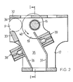
- the weapon simulator has a feed channel 34 for the cartridges, which is formed on the one hand by a cover plate 32 and on the other hand by a guide strut 33. There is also a discharge channel 35 for the cartridges, which is formed by two guide walls 36 and 37. A transmitter 38 is attached to one guide wall 36 and a receiver 39 is attached to the other guide wall 37. The cartridges passing through the discharge channel 35 can be counted with the transmitter 38 and receiver 39.
- the direction of rotation of the shaft 16 with the cam disks 19, 20 is indicated in FIG. 2 by an arrow 40.
- a cartridge P rests against the cam disk 19, specifically at a point which has a constant radius in a section of the curve. As long as the cartridge rests against this section of the cam disk 19, it will not move. As soon as the radius of the cam disk 19 becomes smaller, the cartridge shifts to the right, as shown in FIG. 2.
- the cartridge P As soon as the cartridge P is ejected, the next cartridge that follows is shifted more rapidly to the right until it touches the cam disk 19.
- the cartridges are thus conveyed at different speeds and experience accelerations and decelerations that correspond to those of an automatic firearm.
- accelerations and decelerations are of course primarily dependent on the cadence of the weapon or the speed of the weapon simulator. However, as far as acceleration and deceleration depend on the shape of the cam disks 19 and 20, they can be controlled by the shape of the cam disks 19 and 20.
Landscapes
- Engineering & Computer Science (AREA)
- General Engineering & Computer Science (AREA)
- Materials For Photolithography (AREA)
- Spectrometry And Color Measurement (AREA)
- Mechanical Operated Clutches (AREA)
- Management, Administration, Business Operations System, And Electronic Commerce (AREA)
- Transmission Devices (AREA)
- Valve-Gear Or Valve Arrangements (AREA)
Description
- Die Erfindung betrifft einen Waffensimulator gemäss dem Oberbegriff des Anspruches.
- Bei einem bekannten Waffensimulator dieser Art (siehe US-PS-2 386 376) werden die aus dem Patronenmagazin zugeführten Patronen in Achsrichtung der Patronen durch ein Förderrad ausgestossen. Dieses Förderrad besitzt eine Anzahl Förderfinger, die schwenkbar am Förderrad angelenkt sind, und die durch Nockenscheiben aus ihrer wirksamen Stellung in ihre unwirksame Stellung verschwenkbar sind. Jeder einzelne Förderfinger dient zum Ausstoss einer Patrone.
- Dieser bekannte Waffensimulator hat zwei Nachteile. Erstens ergibt sich ein komplizierter Aufbau durch das Ausstossen der Patronen in ihrer Achsrichtung. Zweitens ist eine genaue Anpassung der Beschleunigung und Verzögerung der Patronen durch den Waffensimulator an die Beschleunigung und Verzögerung der Patronen in einer Feuerwaffe nicht möglich.
- Die Aufgabe, die mit der vorliegenden Erfindung gelöst werden soll, besteht in der Schaffung eines Waffensimulators, der die Munition in der selben Weise wie eine Feuerwaffe mit Hilfe der Fördervorrichtung aus einem Munitionsmagazin entnimmt, d. h. die Beschleunigungen und Verzögerungen der Munition, die bei der Entnahme der Munition während eines Seriefeuers aus einer selbsttätigen Feuerwaffe auftreten, sollen mit Hilfe des Waffensimulators ebenfalls erzeugt werden.
- Der erfindungsgemässe Waffensimulator weist ausser den Merkmalen im Oberbegriff des Anspruches 1 auch die Merkmale im kennzeichnenden Teil des Anspruches auf.
- Ein Ausführungsbeispiel des erfindungsgemässen Waffensimulators ist anhand der beigefügten Zeichnung im folgenden ausführlich beschrieben. Es zeigt :
- Figur 1 einen Längsschnitt durch den Waffensimulator nach Linie I-I in Fig. 2 und
- Figur 2 einen Querschnitt durch den Waffensimulator nach Linie 11-11 in Fig. 1 in vergrössertem Massstab.
- Gemäss Fig. 1 weist der Waffensimulator einen handelsüblichen Hydromotor 10 auf. Dieser Hydromotor 10 ist über eine Zuführleitung 11 und eine Rücklaufleitung 12 an eine nicht dargestellte Druckmittelquelle angeschlossen. Durch einen Hahnen 13 kann die Zuführleitung 11 gesperrt werden, wodurch der Hydromotor stillsteht. Der Hydromotor 10 besitzt einen Antriebszapfen 14, der über einen Keil 15 eine Welle 16 antreibt. Der Hydromotor 10 ist an einer Wand 17 eines nicht näher dargestellten Gehäuses befestigt, und die Welle 16 ist an einer zweiten Wand 18 dieses Gehäuses drehbar gelagert. Auf dieser Welle 16 sind zwei Nockenscheiben 19, 20 und ein erstes Zahnrad 21 mit Hilfe von Keilen 22, 23 und 24 befestigt. Das erste Zahnrad 21 steht mit einem zweiten Zahnrad 25 in Eingriff, das mit Hilfe eines Zapfens 26 an der Gehäusewand 18 drehbar gelagert ist. Koaxial zum zweiten Zahnrad 25 ist ein Tachometer 27 angeordnet, der über einen Kurbelarm 28 und einen Bolzen 29 vom zweiten Zahnrad 25 angetrieben wird. Der Bolzen 29 ragt in eine Bohrung 30 des Zahnrades 25. Auf das linke Ende der Welle 16 kann eine Handkurbel 31 aufgesteckt werden, von der in Fig. 1 nur das Ende dargestellt ist.
- Gemäss Fig. 2 weist der Waffensimulator einen Zuführkanal 34 für die Patronen auf, der einerseits durch eine Deckplatte 32 und andererseits durch eine Führungsstrebe 33 gebildet wird. Ausserdem ist ein Ableitkanal 35 für die Patronen vorhanden, der durch zwei Führungswände 36 und 37 gebildet wird. An der einen Führungswand 36 ist ein Sender 38 und an der anderen Führungswand 37 ist ein Empfänger 39 befestigt. Mit Sender 38 und Empfänger 39 können die durch den Ableitkanal 35 hindurchgehenden Patronen gezählt werden. Die Drehrichtung der Welle 16 mit den Nockenscheiben 19, 20 ist in Fig. 2 durch einen Pfeil 40 angedeutet.
- Die Wirkungsweise des beschriebenen Waffensimulators ist wie folgt :
- Der Hydromotor 10 wird mit der gewünschten Drehzahl angetrieben, entsprechend der Kadenz der Feuerwaffe, d. h. z. B. 380-700 Schuss pro Minute. Vorzugsweise wird die Drehzahl des Hydromotors 10 durch einen an sich bekannten Regelkreis gesteuert. Zu diesem Regelkreis gehört insbesondere der in Fig. 1 dargestellte Tachometer 27. Da die Welle 16 mit den Nockenscheiben 19 und 20 zur Förderung einer Patrone einen Umdrehung ausführt, wird die Drehzahl des Hydromotors ebenfalls zwischen 380-700 Umdrehung pro Minute liegen.
- Die Form der Kurvenscheiben 19 und 20 ist aus Fig. 2 ersichtlich. Diese Form der Kurvenscheibe 19 und 20 kann den Eigenschaften der selbsttätigen Feuerwaffe angepasst werden, d. h. Beschleunigungen und Verzögerungen der im Zuführkanal 34 befindlichen Patronen sollen soweit nachvollzogen werden, wie dies zur Erprobung des Munitionsmagazins und der Fördervorrichtung erforderlich ist. Diese in der Zeichnung nicht dargestellte Fördervorrichtung transportiert die Patronen aus dem ebenfalls nicht dargestellten Munitionsmagazin in den Zuführkanal 34 und drückt die Patronen gegen die beiden Nockenscheiben 19 und 20.
- Bei jeder Umdrehung der Welle 16 wird mit der Nase der Nockenscheiben 19,20 eine Patrone aus dem Zuführkanal 34 in den Ableitkanal 35 gefördert.
- Gemäss Fig. 2 liegt eine Patrone P an der Nockenscheibe 19 an und zwar an einer Stelle, die in einem Abschnitt der Kurve einen konstanten Radius aufweist. Solange die Patrone an diesem Abschnitt der Nockenscheibe 19 anliegt, wird sie sich nicht bewegen. Sobald der Radius der Nockenscheibe 19 kleiner wird, verschiebt sich die Patrone, gemäss Fig. 2, nach rechts.
- Sobald die Patrone P ausgestossen wird, erfolgt eine raschere Verschiebung der nächstfolgenden Patrone nach rechts bis sie die Nockenscheibe 19 berührt. Somit werden die Patronen mit verschiedenen Geschwindigkeiten gefördert und erfahren Beschleunigungen und Verzögerungen, die denjenigen einer selbsttätigen Feuerwaffe entsprechen.
- Diese Beschleunigungen und Verzögerungen sind selbstverständlich in erster Linie auch von der Kadenz der Waffe bzw. von der Drehzahl des Waffensimulators abhängig. Soweit aber Beschleunigung und Verzögerung von der Form der Nockenscheiben 19 und 20 abhängig sind, können sie durch die Formgebung der Nockenscheiben 19 und 20 gesteuert werden.
Claims (2)
Priority Applications (1)
| Application Number | Priority Date | Filing Date | Title |
|---|---|---|---|
| AT81200975T ATE10233T1 (de) | 1980-09-26 | 1981-09-02 | Waffensimulator. |
Applications Claiming Priority (2)
| Application Number | Priority Date | Filing Date | Title |
|---|---|---|---|
| CH7232/80 | 1980-09-26 | ||
| CH723280 | 1980-09-26 |
Publications (3)
| Publication Number | Publication Date |
|---|---|
| EP0049010A2 EP0049010A2 (de) | 1982-04-07 |
| EP0049010A3 EP0049010A3 (en) | 1982-06-23 |
| EP0049010B1 true EP0049010B1 (de) | 1984-11-07 |
Family
ID=4321932
Family Applications (1)
| Application Number | Title | Priority Date | Filing Date |
|---|---|---|---|
| EP81200975A Expired EP0049010B1 (de) | 1980-09-26 | 1981-09-02 | Waffensimulator |
Country Status (4)
| Country | Link |
|---|---|
| US (1) | US4388826A (de) |
| EP (1) | EP0049010B1 (de) |
| AT (1) | ATE10233T1 (de) |
| DE (1) | DE3167099D1 (de) |
Family Cites Families (4)
| Publication number | Priority date | Publication date | Assignee | Title |
|---|---|---|---|---|
| DE677176C (de) * | 1936-10-20 | 1939-06-20 | Rheinmetall Borsig Akt Ges | Ladeuebungsgeraet |
| US2386376A (en) * | 1941-12-22 | 1945-10-09 | Ncr Co | Magazine testing means |
| US2554714A (en) * | 1945-08-20 | 1951-05-29 | Cons Vultee Aircraft Corp | Machine gun testing device |
| DE1094633B (de) * | 1957-10-08 | 1960-12-08 | Military Training Device Compa | Vorrichtung fuer Ladeuebungen an leichter Flak |
-
1981
- 1981-09-02 AT AT81200975T patent/ATE10233T1/de not_active IP Right Cessation
- 1981-09-02 DE DE8181200975T patent/DE3167099D1/de not_active Expired
- 1981-09-02 EP EP81200975A patent/EP0049010B1/de not_active Expired
- 1981-09-23 US US06/304,823 patent/US4388826A/en not_active Expired - Fee Related
Also Published As
| Publication number | Publication date |
|---|---|
| DE3167099D1 (en) | 1984-12-13 |
| ATE10233T1 (de) | 1984-11-15 |
| EP0049010A2 (de) | 1982-04-07 |
| US4388826A (en) | 1983-06-21 |
| EP0049010A3 (en) | 1982-06-23 |
Similar Documents
| Publication | Publication Date | Title |
|---|---|---|
| DE3617259C2 (de) | ||
| DE2758409B2 (de) | Vorrichtung zum Vereinzeln von Münzen bei der das Vorliegen eines Münzstaus signalisiert wird | |
| EP0418462B1 (de) | Treibladungs-Portionierer für eine mengenvariabel beladbare Ladeschale | |
| EP0450297A1 (de) | Vorrichtung zum Zuführen von Patronen | |
| DE2907831C2 (de) | Vorrichtung zur Ausgabe von Banknoten | |
| EP0529289B1 (de) | Vorrichtung zum Zuführen von Patronen vorwiegend zweier verschiedener Munitionsarten zu einer Gatling-Kanone | |
| EP0049010A2 (de) | Waffensimulator | |
| EP0099963B1 (de) | Trommelmagazin für grosskalibrige Munition | |
| DE1225908B (de) | Eingabevorrichtung fuer kartenfoermige Aufzeichnungstraeger | |
| EP0184008B1 (de) | Ueberwachungseinrichtung von Spätzündern für ein fremdangetriebenes Geschütz | |
| DE3211416C2 (de) | Munitionszuführer mit wenigstens einer Sternradwelle für eine Doppel-Rohrwaffe | |
| DE2228146A1 (de) | Schnellaufdrucker | |
| EP0525373B1 (de) | Vorrichtung zum Zuführen von Patronen vorwiegend zweier verschiedener Munitionsarten zu einer Gatling-Kanone | |
| DE1782884B1 (de) | Vorrichtung zum pneumatischen foerdern von filterstopfen | |
| DE3333280C2 (de) | ||
| DE3827432A1 (de) | Vorrichtung zum entnehmen von zigarettenreihen an der unterseite von magazinschaechten | |
| DE2024672C2 (de) | Magazin für lose Munition mit einem Zuführsystem | |
| DE2256971C2 (de) | Patronenzuführungssystem für Schnellfeuergeschütze | |
| EP0279048B1 (de) | Vorrichtung zum Zuführen von Munition aus einem Behälter zu einer Feuerwaffe | |
| EP0038399B1 (de) | Gurtzuführer einer gasdruckbetätigten automatischen Rohrwaffe mit zwei von je einer Zuführwelle angetriebenen Zuführwellensternen | |
| DE3335374A1 (de) | Typenraddrucker | |
| DE512704C (de) | Maschine zum Sortieren von Registrierkarten | |
| DE3048750A1 (de) | "vorrichtung zum vereinzelten zufuehren von gegenstaenden, insbesondere kugeln" | |
| EP0403776A1 (de) | Patronenmagazin und Patronenzuführvorrichtung | |
| DE517453C (de) | Druckvorrichtung an Tabelliermaschinen, Rechenmaschinen u. dgl. |
Legal Events
| Date | Code | Title | Description |
|---|---|---|---|
| PUAI | Public reference made under article 153(3) epc to a published international application that has entered the european phase |
Free format text: ORIGINAL CODE: 0009012 |
|
| AK | Designated contracting states |
Designated state(s): AT CH DE FR GB SE |
|
| PUAL | Search report despatched |
Free format text: ORIGINAL CODE: 0009013 |
|
| AK | Designated contracting states |
Designated state(s): AT CH DE FR GB SE |
|
| 17P | Request for examination filed |
Effective date: 19820707 |
|
| GRAA | (expected) grant |
Free format text: ORIGINAL CODE: 0009210 |
|
| AK | Designated contracting states |
Designated state(s): AT CH DE FR GB LI SE |
|
| REF | Corresponds to: |
Ref document number: 10233 Country of ref document: AT Date of ref document: 19841115 Kind code of ref document: T |
|
| REF | Corresponds to: |
Ref document number: 3167099 Country of ref document: DE Date of ref document: 19841213 |
|
| ET | Fr: translation filed | ||
| PLBE | No opposition filed within time limit |
Free format text: ORIGINAL CODE: 0009261 |
|
| STAA | Information on the status of an ep patent application or granted ep patent |
Free format text: STATUS: NO OPPOSITION FILED WITHIN TIME LIMIT |
|
| 26N | No opposition filed | ||
| PGFP | Annual fee paid to national office [announced via postgrant information from national office to epo] |
Ref country code: FR Payment date: 19900806 Year of fee payment: 10 |
|
| PGFP | Annual fee paid to national office [announced via postgrant information from national office to epo] |
Ref country code: AT Payment date: 19900808 Year of fee payment: 10 |
|
| PGFP | Annual fee paid to national office [announced via postgrant information from national office to epo] |
Ref country code: GB Payment date: 19900810 Year of fee payment: 10 |
|
| PGFP | Annual fee paid to national office [announced via postgrant information from national office to epo] |
Ref country code: CH Payment date: 19900815 Year of fee payment: 10 |
|
| PGFP | Annual fee paid to national office [announced via postgrant information from national office to epo] |
Ref country code: SE Payment date: 19900816 Year of fee payment: 10 |
|
| PGFP | Annual fee paid to national office [announced via postgrant information from national office to epo] |
Ref country code: DE Payment date: 19900829 Year of fee payment: 10 |
|
| PG25 | Lapsed in a contracting state [announced via postgrant information from national office to epo] |
Ref country code: GB Effective date: 19910902 Ref country code: AT Effective date: 19910902 |
|
| PG25 | Lapsed in a contracting state [announced via postgrant information from national office to epo] |
Ref country code: SE Effective date: 19910903 |
|
| PG25 | Lapsed in a contracting state [announced via postgrant information from national office to epo] |
Ref country code: LI Effective date: 19910930 Ref country code: CH Effective date: 19910930 |
|
| GBPC | Gb: european patent ceased through non-payment of renewal fee | ||
| PG25 | Lapsed in a contracting state [announced via postgrant information from national office to epo] |
Ref country code: FR Effective date: 19920529 |
|
| REG | Reference to a national code |
Ref country code: CH Ref legal event code: PL |
|
| PG25 | Lapsed in a contracting state [announced via postgrant information from national office to epo] |
Ref country code: DE Effective date: 19920602 |
|
| REG | Reference to a national code |
Ref country code: FR Ref legal event code: ST |
|
| EUG | Se: european patent has lapsed |
Ref document number: 81200975.1 Effective date: 19920408 |