EP0048445B1 - Différentiel de transmission - Google Patents
Différentiel de transmission Download PDFInfo
- Publication number
- EP0048445B1 EP0048445B1 EP81107347A EP81107347A EP0048445B1 EP 0048445 B1 EP0048445 B1 EP 0048445B1 EP 81107347 A EP81107347 A EP 81107347A EP 81107347 A EP81107347 A EP 81107347A EP 0048445 B1 EP0048445 B1 EP 0048445B1
- Authority
- EP
- European Patent Office
- Prior art keywords
- sun gear
- axis
- differential
- pin
- housing
- Prior art date
- Legal status (The legal status is an assumption and is not a legal conclusion. Google has not performed a legal analysis and makes no representation as to the accuracy of the status listed.)
- Expired
Links
- 230000005540 biological transmission Effects 0.000 claims description 6
- 230000003100 immobilizing effect Effects 0.000 description 1
- 238000003754 machining Methods 0.000 description 1
- 238000004519 manufacturing process Methods 0.000 description 1
- 210000002445 nipple Anatomy 0.000 description 1
- 230000000007 visual effect Effects 0.000 description 1
Images
Classifications
-
- B—PERFORMING OPERATIONS; TRANSPORTING
- B60—VEHICLES IN GENERAL
- B60K—ARRANGEMENT OR MOUNTING OF PROPULSION UNITS OR OF TRANSMISSIONS IN VEHICLES; ARRANGEMENT OR MOUNTING OF PLURAL DIVERSE PRIME-MOVERS IN VEHICLES; AUXILIARY DRIVES FOR VEHICLES; INSTRUMENTATION OR DASHBOARDS FOR VEHICLES; ARRANGEMENTS IN CONNECTION WITH COOLING, AIR INTAKE, GAS EXHAUST OR FUEL SUPPLY OF PROPULSION UNITS IN VEHICLES
- B60K17/00—Arrangement or mounting of transmissions in vehicles
- B60K17/04—Arrangement or mounting of transmissions in vehicles characterised by arrangement, location or kind of gearing
- B60K17/16—Arrangement or mounting of transmissions in vehicles characterised by arrangement, location or kind of gearing of differential gearing
-
- F—MECHANICAL ENGINEERING; LIGHTING; HEATING; WEAPONS; BLASTING
- F16—ENGINEERING ELEMENTS AND UNITS; GENERAL MEASURES FOR PRODUCING AND MAINTAINING EFFECTIVE FUNCTIONING OF MACHINES OR INSTALLATIONS; THERMAL INSULATION IN GENERAL
- F16H—GEARING
- F16H48/00—Differential gearings
- F16H48/06—Differential gearings with gears having orbital motion
- F16H48/08—Differential gearings with gears having orbital motion comprising bevel gears
- F16H2048/082—Differential gearings with gears having orbital motion comprising bevel gears characterised by the arrangement of output shafts
-
- F—MECHANICAL ENGINEERING; LIGHTING; HEATING; WEAPONS; BLASTING
- F16—ENGINEERING ELEMENTS AND UNITS; GENERAL MEASURES FOR PRODUCING AND MAINTAINING EFFECTIVE FUNCTIONING OF MACHINES OR INSTALLATIONS; THERMAL INSULATION IN GENERAL
- F16H—GEARING
- F16H48/00—Differential gearings
- F16H48/06—Differential gearings with gears having orbital motion
- F16H48/08—Differential gearings with gears having orbital motion comprising bevel gears
- F16H2048/085—Differential gearings with gears having orbital motion comprising bevel gears characterised by shafts or gear carriers for orbital gears
-
- F—MECHANICAL ENGINEERING; LIGHTING; HEATING; WEAPONS; BLASTING
- F16—ENGINEERING ELEMENTS AND UNITS; GENERAL MEASURES FOR PRODUCING AND MAINTAINING EFFECTIVE FUNCTIONING OF MACHINES OR INSTALLATIONS; THERMAL INSULATION IN GENERAL
- F16H—GEARING
- F16H48/00—Differential gearings
- F16H48/38—Constructional details
- F16H2048/387—Shields or washers
-
- F—MECHANICAL ENGINEERING; LIGHTING; HEATING; WEAPONS; BLASTING
- F16—ENGINEERING ELEMENTS AND UNITS; GENERAL MEASURES FOR PRODUCING AND MAINTAINING EFFECTIVE FUNCTIONING OF MACHINES OR INSTALLATIONS; THERMAL INSULATION IN GENERAL
- F16H—GEARING
- F16H48/00—Differential gearings
- F16H48/38—Constructional details
- F16H48/40—Constructional details characterised by features of the rotating cases
Definitions
- the present invention relates to transmission differentials used in particular for driving the driving wheels of motor vehicles and comprising a housing containing two driven conical planetaries and conical driving satellites of the latter mounted idly on an axis mounted through corresponding orifices arranged in said housing.
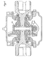
- Ori knows many devices for immobilizing the satellite axes, such as those using nipple screws or elastic pins.
- Figure 1 shows .one of these devices which in this case is an elastic pin system 100.
- These devices have the disadvantage of requiring additional parts and requires precise machining, which leads to an increase in the cost of the transmission differential .
- the object of the present invention is to propose a system for displaying and keeping the axis of the planet carrier which avoids the above drawbacks by eliminating all the additional parts.
- the subject of the invention is a transmission differentiator comprising a box containing two conical planetary driven and conical satellites for driving the latter mounted idly on an axis mounted through corresponding orifices formed in the box. , said axis being held in position using a circular stud at the end of the planetary assembly for closing the differential which cooperates with a groove in said axis.
- This stud can be either at the end of an output shaft of a male sun gear or at the end of a female sun gear depending on the architecture of the differential in question.
- Such a device according to the invention has the advantage of being simple, while allowing the planet carrier axis to be released in rotation, which reduces the cases of seizure of the satellites on their axis, and while satisfying the requirement to allow visual manufacturing control to ensure that the components of the differential are in place.
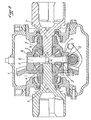
- the differential case shown in FIG. 2 is made up of two parts: a toothed drive crown 1 which is the driven element of the usual bevel gear acting as a flange; and a housing body proper 2 assembled by screws 3, on said crown 1.
- the housing contains two male conical planetary 4 and 5 respectively connected to two opposite output shafts 6 and 7, the planetary 4 being the closing planetary male .
- With these planets cooperate two opposite conical satellites 8 and 9 mounted idly on an axis 10 itself mounted through corresponding orifices 11 and 12 arranged on the housing 2-
- the axis 10 is thus mounted idly in the orifices 11 and 12 of said housing 2.
- This axis 10 is held by means of a circular groove with rectangular section 13 arranged in said axis 10, in which engages a circular stud 14 arranged at the end of the output shaft 6.
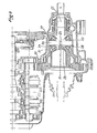
- FIG. 3 illustrates another differential architecture comprising the device of the invention.
- the differential housing of FIG. 3 is made up of two parts: a toothed drive crown 20 which is the driven element of the usual bevel gear; an actual housing body 21 which is integral with said crown 20.
- the housing contains a conical male sun gear 22 and a closing female conical sun gear 23. With these planets cooperate two opposite conical satellites 24 and 25 mounted idly on an axis 26 itself even mounted through corresponding orifices 27 and 28 arranged in the housing 21.
- the axis 26 is thus mounted idly in the orifices 27 and 28 of said housing 21.
- This axis 26 is held by means of a circular groove with rectangular section 29 arranged in said axis 26, in which a circular stud 30 made at the end of the closing female sun gear 23 engages.
Landscapes
- Engineering & Computer Science (AREA)
- Mechanical Engineering (AREA)
- General Engineering & Computer Science (AREA)
- Chemical & Material Sciences (AREA)
- Combustion & Propulsion (AREA)
- Transportation (AREA)
- Retarders (AREA)
Applications Claiming Priority (2)
| Application Number | Priority Date | Filing Date | Title |
|---|---|---|---|
| FR8020211 | 1980-09-19 | ||
| FR8020211A FR2490764A1 (fr) | 1980-09-19 | 1980-09-19 | Differentiel de transmission |
Publications (2)
| Publication Number | Publication Date |
|---|---|
| EP0048445A1 EP0048445A1 (fr) | 1982-03-31 |
| EP0048445B1 true EP0048445B1 (fr) | 1983-05-18 |
Family
ID=9246102
Family Applications (1)
| Application Number | Title | Priority Date | Filing Date |
|---|---|---|---|
| EP81107347A Expired EP0048445B1 (fr) | 1980-09-19 | 1981-09-17 | Différentiel de transmission |
Country Status (8)
| Country | Link |
|---|---|
| US (1) | US4467672A (Direct) |
| EP (1) | EP0048445B1 (Direct) |
| AR (1) | AR224467A1 (Direct) |
| CA (1) | CA1178090A (Direct) |
| DE (1) | DE3160320D1 (Direct) |
| ES (1) | ES8206787A1 (Direct) |
| FR (1) | FR2490764A1 (Direct) |
| PT (1) | PT73675B (Direct) |
Families Citing this family (21)
| Publication number | Priority date | Publication date | Assignee | Title |
|---|---|---|---|---|
| JPH0637141B2 (ja) * | 1985-01-30 | 1994-05-18 | スズキ株式会社 | 二輪・四輪駆動切換装置 |
| DE3843687C2 (de) * | 1988-05-06 | 1998-07-16 | Bayerische Motoren Werke Ag | Axialsicherungselement für die Ausgleichsräderwelle eines Differentialgetriebes |
| US4860614A (en) * | 1988-07-26 | 1989-08-29 | Deere & Company | Transmission differential |
| US4901599A (en) * | 1988-12-29 | 1990-02-20 | Dana Corporation | Cross pin retainer block for a bevel gear differential |
| FR2686958A1 (fr) * | 1992-02-04 | 1993-08-06 | Renault | Mecanisme de transmission differentiel pour l'entrainement des roues motrices d'un vehicule automobile. |
| US5233757A (en) * | 1992-10-19 | 1993-08-10 | General Motors Corporation | Method of assembling a motor vehicle differential |
| US5273498A (en) * | 1992-12-07 | 1993-12-28 | New Venture Gear, Inc. | Differential mechanism |
| FR2702532B1 (fr) * | 1993-03-09 | 1995-04-21 | Renault | Différentiel de transmission pour boîte de vitesses étanche. |
| US6146304A (en) * | 1998-12-22 | 2000-11-14 | Caterpillar Inc. | Vehicle differential |
| US6254505B1 (en) * | 1999-11-23 | 2001-07-03 | Auburn Gear, Inc. | Differential cross pin retention |
| US6196942B1 (en) | 1999-12-16 | 2001-03-06 | Dana Corporation | Modular unitized differential |
| US6409626B1 (en) | 2000-06-29 | 2002-06-25 | Spicer Technology, Inc. | Axle assembly having a differential case adjustably secured to a housing |
| DE10163044A1 (de) * | 2001-12-21 | 2003-06-05 | Daimler Chrysler Ag | Achsgetriebe |
| US6949046B2 (en) * | 2003-10-17 | 2005-09-27 | Arvinmeritor Technology, Llc | Gear to case assembly for drive axle |
| DE102004012906A1 (de) * | 2004-03-17 | 2005-10-06 | Daimlerchrysler Ag | Ausgleichsgetriebe für ein Kraftfahrzeug und Verfahren zur Montage desselben |
| DE102004013764B4 (de) * | 2004-03-20 | 2010-06-17 | Audi Ag | Werkzeug zum Drehen einer Kurbelwelle |
| US7591751B2 (en) * | 2007-04-18 | 2009-09-22 | American Axle & Manufacturing, Inc. | Four pinion differential with cross pin retention unit and related method |
| US7901318B2 (en) * | 2007-09-27 | 2011-03-08 | American Axle & Manufacturing, Inc. | Four pinion differential with cross pin retention unit and related method |
| JP4807418B2 (ja) * | 2009-01-27 | 2011-11-02 | トヨタ自動車株式会社 | ディファレンシャル装置 |
| US8764601B2 (en) * | 2011-08-26 | 2014-07-01 | Arvinmeritor Technology, Llc | Carrier with center backbone and dual lateral cases |
| EP3299666B1 (en) * | 2016-09-21 | 2022-08-17 | Meritor Heavy Vehicle Systems Cameri SpA | Differential gear assembly and components thereof |
Family Cites Families (2)
| Publication number | Priority date | Publication date | Assignee | Title |
|---|---|---|---|---|
| US1121803A (en) * | 1914-02-26 | 1914-12-22 | Charles C Coakley | Differential gearing for automobiles. |
| US3310999A (en) * | 1965-06-09 | 1967-03-28 | Ford Motor Co | Differential gearing and axle assembly for an automotive vehicle driveline |
-
1980
- 1980-09-19 FR FR8020211A patent/FR2490764A1/fr active Granted
-
1981
- 1981-09-15 PT PT73675A patent/PT73675B/pt unknown
- 1981-09-17 AR AR286791A patent/AR224467A1/es active
- 1981-09-17 EP EP81107347A patent/EP0048445B1/fr not_active Expired
- 1981-09-17 DE DE8181107347T patent/DE3160320D1/de not_active Expired
- 1981-09-17 US US06/303,022 patent/US4467672A/en not_active Expired - Fee Related
- 1981-09-18 ES ES505603A patent/ES8206787A1/es not_active Expired
- 1981-09-18 CA CA000386210A patent/CA1178090A/fr not_active Expired
Also Published As
| Publication number | Publication date |
|---|---|
| US4467672A (en) | 1984-08-28 |
| FR2490764B1 (Direct) | 1982-10-08 |
| DE3160320D1 (en) | 1983-07-07 |
| ES505603A0 (es) | 1982-08-16 |
| FR2490764A1 (fr) | 1982-03-26 |
| PT73675B (fr) | 1982-11-23 |
| ES8206787A1 (es) | 1982-08-16 |
| EP0048445A1 (fr) | 1982-03-31 |
| PT73675A (fr) | 1981-10-01 |
| CA1178090A (fr) | 1984-11-20 |
| AR224467A1 (es) | 1981-11-30 |
Similar Documents
| Publication | Publication Date | Title |
|---|---|---|
| EP0048445B1 (fr) | Différentiel de transmission | |
| FR2507144A1 (fr) | Direction assistee, notamment pour vehicules utilitaires | |
| FR2488360A1 (fr) | Appareil muni d'un train planetaire, notamment pour un systeme de commande de direction comprenant par exemple un servomecanisme | |
| FR2363471A1 (fr) | Assemblage a moyeu orientable et engrenage planetaire | |
| EP0264513B1 (fr) | Dispositif de transmission à quatre roues motrices | |
| FR2661964A1 (fr) | Dispositif de transmission a differentiel et accouplement a glissement controle. | |
| CA1282262C (fr) | Dispositif de transmission a quatre roues motrices | |
| FR2606713A1 (fr) | Transmission pour vehicule a roues ou a chenilles, comportant un dispositif de freinage et un groupe de direction | |
| US4625588A (en) | Continuously varying planetary mechanical transmission system | |
| FR2682732A1 (fr) | Differentiel a maintien central des axes porte-satellites. | |
| EP3645906B1 (fr) | Pompe hydraulique pour interface de connexion hydraulique d'un mecanisme d'embrayage | |
| EP3049693B1 (fr) | Dispositif réducteur de vitesse angulaire | |
| FR2501621A1 (fr) | Perfectionnements aux systemes moteurs pour bateaux susceptibles de passer de la marche a grande vitesse a celle a vitesse reduite | |
| EP0629795B1 (fr) | Système de refroidissement d'un réducteur à engrenages d'entraînement d'un barbotin de véhicule chenillé ou à roues | |
| FR2582264A1 (fr) | Transmission integrale et differentielle | |
| FR2731259A1 (fr) | Mecanisme de transmission differentiel | |
| FR2609135A1 (fr) | Dispositif de differentiel a transfert de couple | |
| EP0139578A1 (fr) | Variateur à convertisseur inverseur intégré | |
| EP0090326A1 (fr) | Dispositif de montage de couronnes de trains d'engrenages planétaires | |
| EP4506589A1 (fr) | Dispositif de changement de vitesse et engin de mobilité associé | |
| FR2589109A1 (fr) | Dispositif de transmission a quatre roues motrices | |
| FR2670857A1 (fr) | Variateur de vitesse. | |
| FR2657309A1 (fr) | Groupe motopropulseur transversal equipe d'une prise de puissance. | |
| EP0364318B1 (fr) | Module de couplage pour transmission à quatre roues motrices | |
| FR2771695A1 (fr) | Repartiteur rotatif de force d'entrainement et de freinage sur deux arbres en ligne independants |
Legal Events
| Date | Code | Title | Description |
|---|---|---|---|
| PUAI | Public reference made under article 153(3) epc to a published international application that has entered the european phase |
Free format text: ORIGINAL CODE: 0009012 |
|
| AK | Designated contracting states |
Designated state(s): BE DE GB IT LU NL SE |
|
| RBV | Designated contracting states (corrected) |
Designated state(s): BE DE GB IT LU NL SE |
|
| 17P | Request for examination filed |
Effective date: 19820504 |
|
| ITF | It: translation for a ep patent filed | ||
| GRAA | (expected) grant |
Free format text: ORIGINAL CODE: 0009210 |
|
| AK | Designated contracting states |
Designated state(s): BE DE GB IT NL SE |
|
| REF | Corresponds to: |
Ref document number: 3160320 Country of ref document: DE Date of ref document: 19830707 |
|
| PLBE | No opposition filed within time limit |
Free format text: ORIGINAL CODE: 0009261 |
|
| STAA | Information on the status of an ep patent application or granted ep patent |
Free format text: STATUS: NO OPPOSITION FILED WITHIN TIME LIMIT |
|
| 26N | No opposition filed | ||
| PGFP | Annual fee paid to national office [announced via postgrant information from national office to epo] |
Ref country code: BE Payment date: 19840630 Year of fee payment: 4 |
|
| PGFP | Annual fee paid to national office [announced via postgrant information from national office to epo] |
Ref country code: SE Payment date: 19840930 Year of fee payment: 4 |
|
| PGFP | Annual fee paid to national office [announced via postgrant information from national office to epo] |
Ref country code: NL Payment date: 19870930 Year of fee payment: 7 |
|
| PGFP | Annual fee paid to national office [announced via postgrant information from national office to epo] |
Ref country code: DE Payment date: 19890530 Year of fee payment: 9 |
|
| PGFP | Annual fee paid to national office [announced via postgrant information from national office to epo] |
Ref country code: GB Payment date: 19890831 Year of fee payment: 9 |
|
| PG25 | Lapsed in a contracting state [announced via postgrant information from national office to epo] |
Ref country code: SE Effective date: 19890918 |
|
| ITTA | It: last paid annual fee | ||
| PG25 | Lapsed in a contracting state [announced via postgrant information from national office to epo] |
Ref country code: BE Effective date: 19890930 |
|
| BERE | Be: lapsed |
Owner name: REGIE NATIONALE DES USINES RENAULT Effective date: 19890930 |
|
| PG25 | Lapsed in a contracting state [announced via postgrant information from national office to epo] |
Ref country code: NL Effective date: 19900401 |
|
| NLV4 | Nl: lapsed or anulled due to non-payment of the annual fee | ||
| PG25 | Lapsed in a contracting state [announced via postgrant information from national office to epo] |
Ref country code: GB Effective date: 19900917 |
|
| GBPC | Gb: european patent ceased through non-payment of renewal fee | ||
| PG25 | Lapsed in a contracting state [announced via postgrant information from national office to epo] |
Ref country code: DE Effective date: 19910601 |
|
| EUG | Se: european patent has lapsed |
Ref document number: 81107347.7 Effective date: 19900521 |