EP0048444A2 - Method and shuttering element for producing slit walls in the ground - Google Patents
Method and shuttering element for producing slit walls in the ground Download PDFInfo
- Publication number
- EP0048444A2 EP0048444A2 EP81107344A EP81107344A EP0048444A2 EP 0048444 A2 EP0048444 A2 EP 0048444A2 EP 81107344 A EP81107344 A EP 81107344A EP 81107344 A EP81107344 A EP 81107344A EP 0048444 A2 EP0048444 A2 EP 0048444A2
- Authority
- EP
- European Patent Office
- Prior art keywords
- formwork element
- slot section
- concrete
- plate
- section
- Prior art date
- Legal status (The legal status is an assumption and is not a legal conclusion. Google has not performed a legal analysis and makes no representation as to the accuracy of the status listed.)
- Granted
Links
Images


Classifications
-
- E—FIXED CONSTRUCTIONS
- E02—HYDRAULIC ENGINEERING; FOUNDATIONS; SOIL SHIFTING
- E02D—FOUNDATIONS; EXCAVATIONS; EMBANKMENTS; UNDERGROUND OR UNDERWATER STRUCTURES
- E02D5/00—Bulkheads, piles, or other structural elements specially adapted to foundation engineering
- E02D5/18—Bulkheads or similar walls made solely of concrete in situ
- E02D5/182—Bulkheads or similar walls made solely of concrete in situ using formworks to separate sections
-
- E—FIXED CONSTRUCTIONS
- E02—HYDRAULIC ENGINEERING; FOUNDATIONS; SOIL SHIFTING
- E02D—FOUNDATIONS; EXCAVATIONS; EMBANKMENTS; UNDERGROUND OR UNDERWATER STRUCTURES
- E02D5/00—Bulkheads, piles, or other structural elements specially adapted to foundation engineering
- E02D5/18—Bulkheads or similar walls made solely of concrete in situ
- E02D5/185—Bulkheads or similar walls made solely of concrete in situ with flexible joint members between sections
Definitions
- the invention relates to a method for producing diaphragm walls, in which wall sections adjoining one another on the end face are concreted in succession and sealed by a vertically running joint tape, preferably provided with a horizontal shoulder in the area of the base plate connection, for which purpose a slot section is excavated in the length of the wall section to be produced, a formwork element extending over the diaphragm wall height, partially receiving the joint tape, which on its front side facing the slot section has projections for interlocking the individual wall sections, is arranged vertically at the end of the slot section, the slot section is provided with a reinforcement cage, concrete in Contractor procedure is introduced into the slot section, the subsequent slot section is excavated on the back of the formwork element and the formwork element after the partially embedded nated joint tape is lifted vertically.
- the formwork element is pulled in the vertical direction, as is generally customary, for which purpose push-off cylinders act on the underside of a cross member which is fastened to the upper end of the formwork element projecting above the earth's surface.
- the formwork element tapers towards its lower end in order to facilitate vertical pulling.
- This vertical pulling which can possibly be made easier in a known manner by using formwork removal means such as greases or oils applied to the formwork element, poses a danger to the joint tape and its correct arrangement. This proves the long relative movement between the formwork element and the released joint tape when pulling vertically in the direction of extension of both parts as particularly disadvantageous.
- the joint tape adheres locally to the formwork element, the joint tape can easily tear, especially since penetration of concrete slurry along the joint tape into the formwork element cannot always be prevented despite the transverse flange provided on the joint tape, which is supposed to seal against the formwork element.
- the formwork elements can often no longer be pulled even after the above-mentioned auxiliary measures have been used after the concrete has more or less completely set, which is particularly the case with deep diaphragm walls is the case.
- drawing may have to be started early, for example 3 to 4 hours after the start of the contractor procedure, which in the case of deep slots means a step-by-step drawing that begins before the relevant slot wall section is filled with concrete. It can be seen that pulling forces are already transferred to the joint tape before it is fixed in its upper areas in the more or less strongly set concrete.
- Another source for improper joint tape sealing is another source for improper joint tape sealing.
- formwork elements There two different formwork elements are provided, namely a box-shaped formwork element with a corresponding thickness in the contact area on the diaphragm walls, which largely makes it impossible for the concrete to pass to the rear of the formwork element, and a narrow formwork element in the form of a plate, the inclined walls of which slant towards one another from the longitudinal edges project and end at a distance from each other to accommodate the joint tape.
- This formwork element which is thin on its sides opposite the walls of the slot, has a trapezoidal cross section which corresponds to the toothed recess to be formed in the band section to be produced. Accordingly, the formwork element is less wide than the slot and only delimits the slot in a central area.
- the freshly filled concrete can indeed laterally flow past the formwork element, without the latter is flexed more in the longitudinal direction, but the diaphragm wall portion made receive frontally no smooth finish as is to be required for a single w andtransport slot wall without Erdei circuiting.
- the invention has for its object to improve the above-mentioned method so that the risk of damage or displacement of the joint tape is largely eliminated from its intended sealing position, while a simple handy formwork element should be used at the same time.
- This object is achieved in that the concrete introduced into the slot section for filling voids is also passed to the rear of the formwork element, that when or after the subsequent slot section is excavated, concrete adhering to the back of the formwork element is chiseled off and that the formwork element before it is lifted vertically from the manufactured wall section into the subsequent slot section into the side.
- the formwork element does not have to be pulled after a short time, but can be done, for example, 24 to 48 hours after concreting, which is also advantageous from an organizational point of view.
- the formwork element is still not lost and can be used again because on the one hand the back of the formwork element is chiseled free and therefore the adhesion to the concrete is limited to the front of the formwork element and on the other hand the formwork element is not pulled vertically but pushed off to the side, with the push-off force being targeted can be brought up to the height at which the formwork element has not yet detached.
- Existing concrete bridges also tear between the front and the back of the formwork element, which do not cause any problems due to the comparatively small thickness of the formwork element.
- the lateral pressing of the formwork element leads to a particularly short relative movement between the formwork element and the joint tape, so that the risk of tearing is low.
- the joint tape is fixed in its sealing position by the already largely set concrete, even with deep diaphragm walls over the entire length of the joint tape.
- the intended chiseling off of the concrete does not make the process much more difficult, since the access to the rear of the formwork element is provided in any case by lifting the subsequent slot section and since the adhering concrete can be chiseled off comparatively easily from the smooth back of the formwork element.
- a chisel tool must also be used when excavating the subsequent slot section.
- the concrete can be guided laterally around the formwork element to the rear, especially since breakouts can also be expected in the side walls of the excavated slot and a thin formwork element then offers no significant resistance to the flow around the concrete.
- a formwork element which essentially closes off the diaphragm wall section and to be independent of any accidentalities caused by the respective geological formation, it makes sense to guide the concrete through the formwork element to the rear side thereof.
- connections can be made at predetermined longitudinal distances between the front and the back of the formwork element, the connection cross-sections being dimensioned such that the concrete bridges penetrating the formwork element tear when the formwork element is pushed away from the side with a predetermined amount of force.
- the invention also relates to a formwork element for carrying out the method according to the invention, consisting of an elongate plate with a flat rear side and with two stiffening members provided on the front side of the plate and running essentially over the entire length of the plate, which have transverse outer surfaces inclined to one another and between them Form a receptacle for the part of the joint tape to be embedded in the adjoining wall section.
- Such a formwork element is, as stated, already known (US Pat. No. 3,464,665), even if it is only of training a toothed recess in the diaphragm wall section and not to limit the diaphragm wall section over its entire thickness.
- Such a plate-shaped thin formwork element is particularly suitable for carrying out the method described above if its width is adapted to the diaphragm wall thickness.
- this formwork element is designed such that the stiffening members also have outer surfaces which are inclined in the longitudinal direction. This measure is made possible by pressing the formwork element sideways before lifting it out. It not only leads to the fact that the adjoining wall sections are interlocked with one another in the vertical direction in addition to in the horizontal direction - which was previously only possible with concrete formwork elements remaining in the diaphragm wall (DE-OS 19 25 025) - in addition, in Interest in protecting the joint tape ensures that the formwork element must necessarily be pressed laterally to a predetermined extent, for example 20 cm, before it can be lifted vertically. A vertical pull in the usual way is thus excluded.
- Lifting cylinders which can be extended and retracted can be integrated into the formwork element with longitudinal distances of, for example, 3 to 4 m and can be extended to an extent of, for example, 20 cm required for lateral pressing.
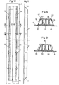
- Figures 1 to 3 each show stages in the plan view (top) and in a vertical longitudinal section (bottom) with a shortened slot length in the manufacture of a subsequent slot wall section.
- FIG. 4 to 7 show the first embodiment of the formwork element in a front view and a side view, in each case a central region of the formwork element being omitted, and in the two sections VI-VI and VII-VII made clear in FIG. 4.
- Fig. 8 shows a perspective view, also with the omission of the central area, the end face of the wall section produced, the partially broken joint tape including the molded shoulder in the area of the lower sole plate is also shown.
- Fig. 9 shows a perspective view of the joint between two adjoining vand sections with the joint tape.
- Figures 10 to 13 show the second embodiment of the formwork element, again in front view, side view and in two characteristic sections indicated in Fig. 10.
- Figures 1 to 3 illustrate the operation in the manufacture of a diaphragm wall section.
- guide walls 1 and 2 are set in a known manner, which protrude, for example, approximately 1.5 m deep into the ground and determine the width of the slot to be excavated and thus the slot wall thickness.
- the arrangement of the upper edge 3 of the guide walls 1 and 2 in alignment with the surface 4 of the soil 5 can be seen from the figures.
- Fig. 1 is based on a concrete wall section 6 with a not yet drawn or raised formwork element 7.
- a subsequent slot section 8 is excavated in a known manner.
- the back of the formwork element is cleaned by lowering a tool 10 with chisels 11, which is already known for crushing the earth material to be excavated, into the slot section 8.
- This tool 10 has been equipped with toothed strips 12 which chisel off the concrete 13 adhering to the rear of the formwork element 7.
- the tool 10 is provided with an inclined run-up surface 14 which, in accordance with the force decomposition indicated by arrows, ensures that the toothed strips 12 are pressed against the smooth rear side of the formwork element 7.
- the formwork element 7 After cleaning the back of the formwork element 7, this is pressed laterally into the slot section 8, as indicated in FIG. 2, which can be done in the manner described above and is not indicated in more detail.
- the formwork element 7 detaches from the joint tape 15 previously received in it, which, as indicated, is approximately half embedded in the wall section 6 that has already been produced. After the lateral pressing, the formwork element 7 is lifted out of the slot section 8.
- the mold member 7 is provided with a new joint tape 15 'and corresponding to FIG. 3 on the loading placed the re its concrete wall portion 6 facing away from the end of the slit section 8.
- a reinforcement cage is arranged in the slot section 8 in a known manner, whereupon it is filled with concrete in the contractor process.
- This concrete penetrates through the formwork element 7 or past its narrow longitudinal edges into the cavities 16 indicated in FIG. 3 on the back of the formwork element, as a result of which the concrete 13 shown in FIG. 1 and later demolished is formed.
- the formwork element according to Figures 4 to 7 consists of an elongated plate 21, from the front of which two stiffening rails 22 protrude, which extend parallel to one another, form a slot-shaped receptacle 23 for the joint tape 15 and have end faces 24 which are inclined in the longitudinal direction.
- the stiffening rails 22 are designed as a hollow profile with an inner leg 25 running perpendicular to the plate 21 and an inclined outer leg 26.
- the parts 21, 24, 25 and 26 are welded together.
- the end faces 24 and the outer legs 26 lead to a shape of the stiffening rails 22 that is conical in both the longitudinal and transverse directions.
- openings 27 are provided in the plate 21 at regular intervals in the longitudinal direction, which taper from the front to the rear of the plate 21.
- projections 28 are arranged on the outside of each stiffening rail, which in the transverse direction have inclined outer surfaces 29 and additionally inclined outer surfaces 30 in the longitudinal direction, which are each formed by welded sheet metal pieces and delimit closed cavities.
- the projections 28 are arranged in pairs next to one another and distributed over the length of the plate 21.
- the projections 28 are each arranged in the middle between the openings 27, which are likewise provided in pairs.
- FIG. 8 shows a finished wall section 32 made of concrete, which is also referred to as a lamella, and reveals the toothing recesses 33 which originate from the projections 2 8 of the formwork element.
- the stiffening rails 22 have also created a recess 34.
- the joint tape 15 can be seen, the freely projecting section 36 was received in the slot-shaped receptacle 23 of the formwork element. Also shown in the area of the not shown sole plate on the joint tape 15 is the projection 37, which seals against water penetrating in the vertical direction.
- FIG. 9 shows the wall section 32 with the adjoining wall section 38 and reveals the transverse toothing between the two wall sections and the position of the joint sealing tape 15, which is provided with a transverse flange 35 projecting on both sides.
- the second embodiment of the formwork element shown in FIGS. 10 to 13 has a plate 41 which has on its front side two stiffening members 42 and 43 which extend in the longitudinal direction and are designed and arranged symmetrically to the longitudinal center plane.
- the stiffening members 42 and 43 are releasably connected to the plate 41 by screws 44 (Figs. 12 & 12), so that the plate 41 can, if necessary, be exchanged for another plate of different widths.
- the stiffening members 42 and 43 each consist of a double T-beam 45 or 46, one flange of which rests on the plate 41 and the other flange of which forms a pressing surface 47 or 48 parallel to the plate.
- Inner surfaces 51, 52 are welded to the mutually adjacent inner ends of the flanges of the carriers 45 and 46, which form a receptacle 53 for the joint tape between them.
- the outer flanges of the supports 45 and 46 are partially shortened with an alternating inclination with respect to the longitudinal direction and with an inclination in the cross-sectional profile and are connected to one another at their outer ends by welded-in outer surfaces 55 and 56.
- stiffening members 42 and 43 are also provided at their ends with longitudinally inclined end faces 58 and 59, so that they form closed hollow profiles. Furthermore, pairs of openings 60 and 61 are provided on the outside of the stiffening members 42 and 43 in the area of their strongest constriction, which taper conically from the front to the rear of the plate 41.
- the plates 21 and 41 are provided, in a manner not shown but known, with connecting means in order to connect two or more formwork elements to one another on the end face and thereby to obtain a length corresponding to the diaphragm wall height.
Abstract
Description
Die Erfindung betrifft ein Verfahren zum Herstellen von Schlitzwänden, bei dem stirnseitig aneinander anschließende Wandabschnitte nacheinander betoniert und durch ein vertikal verlaufendes, vorzugsweise mit einem horizontalen Ansatz im Bereich des Sohlplattenanschlusses versehenes Fugenband abgedichtet werden, wozu jeweils ein Schlitzabschnitt in Länge des herzustellenden Wandabschnitts ausgehoben wird, ein sich Über die Schlitzwandhöhe erstreckendes, das Fugenband teilweise aufnehmendes Schalungselement, das auf seiner in den Schlitzabschnitt weisenden Vorderseite Vorsprünge zur gegenseitigen Verzahnung der einzelnen Wandabschnitte aufweist, am Ende des Schlitzabschnitts vertikal in diesem angeordnet wird, der Schlitzabschnitt mit einem Bewehrungskorb versehen wird, Beton im Kontraktorverfahren in den Schlitzabschnitt eingeführt wird, der anschließende Schlitzabschnitt auf der Rückseite des Schalungselements ausgehoben wird und das Schalungselement nach Freigabe des teilweise einbetonierten Fugenbandes vertikal ausgehoben wird.The invention relates to a method for producing diaphragm walls, in which wall sections adjoining one another on the end face are concreted in succession and sealed by a vertically running joint tape, preferably provided with a horizontal shoulder in the area of the base plate connection, for which purpose a slot section is excavated in the length of the wall section to be produced, a formwork element extending over the diaphragm wall height, partially receiving the joint tape, which on its front side facing the slot section has projections for interlocking the individual wall sections, is arranged vertically at the end of the slot section, the slot section is provided with a reinforcement cage, concrete in Contractor procedure is introduced into the slot section, the subsequent slot section is excavated on the back of the formwork element and the formwork element after the partially embedded nated joint tape is lifted vertically.
Ein solches Verfahren, bei dem vor dem Ausheben des Schalungselements der anschließende Schlitzabschnitt ausgehoben wird, ist bereits bekannt (US-PS 3 464 665). Hier ist allerdings über das beim Einbringen des Betons angewendete Verfahren wie auch über die Gestaltung des Fugenbandes im Bereich des Sohlplattenanschlusses nichts gesagt. Zur Halterung des Fugenbandes sind zwei Schläuche vorgesehen, die sich durch das Schalungselement erstrecken und in aufgeblasenem Zustand das Fugenband in seinem hinteren Bereich innerhalb des Schalungselementes festklemmen. Vor dem Ziehen des Schalungselements wird der Druck aus den Schläuchen abgelassen und dadurch das Fugenband freigegeben.Such a method, in which the subsequent slot section is excavated before the formwork element is lifted out, is already known (US Pat. No. 3,464,665). Here, however, nothing is said about the method used when pouring the concrete or about the design of the joint tape in the area of the base plate connection. To hold the joint tape, two hoses are provided which extend through the formwork element and, when inflated, clamp the joint tape in its rear region within the formwork element. Before the formwork element is pulled, the pressure is released from the hoses, thereby releasing the joint tape.
Das Schalungselement wird wie allgemein üblich in vertikaler Richtung gezogen, wozu Abdrückzylinder an der Unterseite eines Querträgers angreifen, der am oberen Ende des über die Erdoberfläche aufragenden Schalungselements befestigt ist. Außerdem verjüngt sich das Schalungselement in Richtung auf sein unteres Ende, um das vertikale Ziehen zu erleichtern. Dieses vertikale Ziehen, das ggf. in bekannter Weise auch durch Verwendung von auf das Schalungselement aufgebrachten Entschalungsmitteln wie Fette oder Öle erleichtert werden kann, stellt eine Gefahr für das Fugenband und seine ordnungsgemäße Anordnung dar. Hier erweist sich die lange Relativbewegung zwischen dem Schalungselement und dem freigegebenen Fugenband beim vertikalen Ziehen in der Erstreckungsrichtung beider Teile als besonders nachteilig. Durch örtliches Anhaften des Fugenbandes am Schalungselement kommt es leicht zum Reißen des Fugenbandes, zumal ein Eindringen von Betonschlempe längs des Fugenbandes in das Schalungselement trotz des am Fugenband vorgesehenen Querflansches, der sich abdichtend an das Schalungselement anlegen soll, nicht immer verhindert werden kann. Außerdem lassen sich die Schalungselemente selbst bei Anwendung der vorgenannten Hilfsmaßnahmen nach einem mehr oder weniger vollständigen Abbinden des Betons häufig nicht mehr ziehen, was insbesondere bei tiefen Schlitzwänden der Fall ist. Daher muß ggf. frühzeitig, beispielsweise bereits 3 bis 4 Stunden nach Beginn des Kontraktorverfahrens mit dem Ziehen begonnen werden, was bei tiefen Schlitzen ein schrittweises Ziehen bedeutet, das bereits beginnt, bevor der betreffende Schlitzwandabschnitt mit Beton gefüllt ist. Es ist ersichtlich, daß hierbei bereits Ziehkräfte auf das Fugenband übertragen werden, bevor dieses in seinen oberen Bereichen im bereits mehr oder minder stark abgebundenen Beton fixiert ist. Hier liegt eine weitere Quelle für eine nicht ordnungsgemäße Fugenbandabdichtung.The formwork element is pulled in the vertical direction, as is generally customary, for which purpose push-off cylinders act on the underside of a cross member which is fastened to the upper end of the formwork element projecting above the earth's surface. In addition, the formwork element tapers towards its lower end in order to facilitate vertical pulling. This vertical pulling, which can possibly be made easier in a known manner by using formwork removal means such as greases or oils applied to the formwork element, poses a danger to the joint tape and its correct arrangement. This proves the long relative movement between the formwork element and the released joint tape when pulling vertically in the direction of extension of both parts as particularly disadvantageous. If the joint tape adheres locally to the formwork element, the joint tape can easily tear, especially since penetration of concrete slurry along the joint tape into the formwork element cannot always be prevented despite the transverse flange provided on the joint tape, which is supposed to seal against the formwork element. In addition, the formwork elements can often no longer be pulled even after the above-mentioned auxiliary measures have been used after the concrete has more or less completely set, which is particularly the case with deep diaphragm walls is the case. For this reason, drawing may have to be started early, for example 3 to 4 hours after the start of the contractor procedure, which in the case of deep slots means a step-by-step drawing that begins before the relevant slot wall section is filled with concrete. It can be seen that pulling forces are already transferred to the joint tape before it is fixed in its upper areas in the more or less strongly set concrete. Here is another source for improper joint tape sealing.
Das bekannte Verfahren ist auch noch in anderer Hinsicht nachteilig. Bisher wollte man stets vermeiden, daß beim Betonieren der Beton bzw. die Schlempe auf die Rückseite des Schalungselements gelangt. Dementsprechend wurde das Schalungselement in seiner Breite der Schlitzdicke eng angepaßt und ggf. das Schalungselement zweiteilig ausgeführt und mittels eines aufblasbaren Schlauches aufgespreizt und dabei fest an die sich gegenüberliegenden Wände des Schlitzes angedrückt (DE-OS 20 23 372). Hierdurch wird nicht nur eine das Ziehen erleichternde geringere Berührungsfläche zwischen dem Schalungselement und dem Beton geschaffen, es entsteht beim Betonieren auch ein erheblicher Überdruck auf der Vorderseite des Schalungselements, der auf das hohe spezifische Gewicht des Betons zurückzuführen ist, das dasjenige der beim Kontraktorverfahren üblicherweise verwendeten Bentonit-Suspension übersteigt. Die daraus resultierenden, im Sinne einer Durchbiegung auf das Schalungselement einwirkenden Kräfte machen ein kastenförmiges versteiftes Schalungselement erforderlich, um Durchbiegungen und daraus resultierende Behinderungen beim späteren Ziehen des Schalungselements zu vermeiden. Ein solches Schalungselement ist naturgemäß voluminös, schwer und unhandlich sowie auch aufwendig. Das gilt insbesondere auch dann, wenn keine die Biegekräfte aufnehmende Querverspannung des Schalungselements innerhalb des Schlitzes vorgesehen ist, was für die US-PS 3 464 665 zutrifft.The known method is also disadvantageous in other respects. Up to now, it has always been wanted to avoid the concrete or slurry from reaching the back of the formwork element during concreting. Accordingly, the formwork element was closely matched in its width to the slot thickness and, if necessary, the formwork element was made in two parts and spread apart by means of an inflatable tube and pressed firmly against the opposite walls of the slot (DE-OS 20 23 372). This not only creates a smaller contact surface between the formwork element and the concrete, which makes pulling easier, it also creates a considerable overpressure on the front of the formwork element during concreting, which is due to the high specific weight of the concrete, which is that which is usually used in the contractor process Bentonite suspension exceeds. The resulting forces acting on the formwork element in the sense of a deflection make a box-shaped stiffened formwork element necessary in order to avoid deflections and the resulting hindrances when the formwork element is subsequently pulled. Such a formwork element is naturally voluminous, heavy and unwieldy and also complex. This is particularly true when there is no transverse tension of the formwork element absorbing the bending forces within the slot, which is true for US Pat. No. 3,464,665.
Dort sind zwei verschiedene Schalungselemente vorgesehen, nämlich ein kastenförmiges Schalungselement mit einer entsprechenden Dicke im Anlagebereich an den Schlitzwänden, wodurch dem Beton ein Passieren zur Rückseite des Schalungselements weitgehend unmöglich gemacht wird, und ein schmales Schalungselement in Form einer Platte,von deren Längskanten aufeinanderzu geneigte Schrägwände vorspringen und zwecks Aufnahme des Fugenbandes im Abstand voneinander enden. Dieses an seinen den Wänden des Schlitzes gegenüberliegenden Seiten dünne Schalungselemente besitzt einen trapezförmigen Querschnitt, der der auszubildenden Verzahnungsaussparung im herzustellenden Bandabschnitt entspricht. Dementsprechend ist das Schalungselement weniger breit als der Schlitz und begrenzt den Schlitz nur in einem mittleren Bereich. Hier kann der frisch eingefüllte Beton zwar seitlich am Schalungselement vorbeifließen, ohne daß dieses in Längsrichtung stärker durchgebogen wird, der hergestellte Schlitzwandabschnitt erhält jedoch stirnseitig keinen glatten Abschluß, wie er für eine ein- wandfreie Schlitzwand ohne Erdeinschlüsse zu fordern ist.There two different formwork elements are provided, namely a box-shaped formwork element with a corresponding thickness in the contact area on the diaphragm walls, which largely makes it impossible for the concrete to pass to the rear of the formwork element, and a narrow formwork element in the form of a plate, the inclined walls of which slant towards one another from the longitudinal edges project and end at a distance from each other to accommodate the joint tape. This formwork element, which is thin on its sides opposite the walls of the slot, has a trapezoidal cross section which corresponds to the toothed recess to be formed in the band section to be produced. Accordingly, the formwork element is less wide than the slot and only delimits the slot in a central area. Here, the freshly filled concrete can indeed laterally flow past the formwork element, without the latter is flexed more in the longitudinal direction, but the diaphragm wall portion made receive frontally no smooth finish as is to be required for a single w andfreie slot wall without Erdei circuiting.
Dementsprechend liegt der Erfindung die Aufgabe zugrunde, das eingangs genannte Verfahren so zu verbessern, daß die Gefahr einer Beschädigung oder Verlagerung des Fugenbandes aus seiner vorgesehenen Abdichtungsstellung weitgehend ausgeschaltet ist, wobei gleichzeitig ein einfaches handliches Schalungselement verwendbar sein soll.Accordingly, the invention has for its object to improve the above-mentioned method so that the risk of damage or displacement of the joint tape is largely eliminated from its intended sealing position, while a simple handy formwork element should be used at the same time.
Diese Aufgabe wird erfindungsgemäß dadurch gelöst, daß der in den Schlitzabschnitt eingeführte Beton zur Auffüllung von Hohlräumen auch auf die Rückseite des Schalungselements geleitet wird, daß beim oder nach dem Ausheben des anschließenden Schlitzabschnitts an der Rückseite des.Schalungselements anhaftender Beton abgemeißelt wird und daß das Schalungselement vor seinem vertikalen Ausheben vom hergestellten Wandabschnitt in den anschließenden Schlitzabschnitt hinein seitlich abgedrückt wird.This object is achieved in that the concrete introduced into the slot section for filling voids is also passed to the rear of the formwork element, that when or after the subsequent slot section is excavated, concrete adhering to the back of the formwork element is chiseled off and that the formwork element before it is lifted vertically from the manufactured wall section into the subsequent slot section into the side.
Diese erfindungsgemäßen Maßnahmen sichern einen Druakausgleich zwischen der Vorderseite und der Rückseite des Schalungselements, so daß dieses kompakt und preiswert ausgebildet werden kann, obwohl es sich über die gesamte Schlitzwanddicke erstreckt und damit einen sauberen Anschluß an den benachbarten Wandabschnitt gewährleistet. Das Ziehen des Schalungselements muß nicht bereits nach kurzer Zeit erfolgen sondern kann beispielsweise 24 bis 48 Stunden nach dem Betonieren vorgenommen werden, was auch organisatorisch von Vorteil ist. Das Schalungselement wird trotzdem nicht eingebüßt und kann wieder verwendet werden, weil einerseits die Rückseite des Schalungselements freigemeißelt wird und daher die Haftung am Beton auf die Vorderseite des Schalungselements begrenzt ist und weil andererseits das Schalungselement nicht vertikal gezogen sondern seitlich abgedrückt wird, wobei die Abdrückkraft gezielt in derjenigen Höhe auf- .gebracht werden kann, an der sich das Schalungselement noch nicht gelöst hat. Dabei reißen auch vorhandene Betonbrücken zwischen der Vorderseite und der Rückseite des Schalungselements, die infolge der vergleichsweise geringen Dicke des Schalungselements zu keinen Problemen führen. Das seitliche Abdrücken des Schalungselements führt zu einer besonders kurzen Relativbewegung zwischen dem Schalungselement und dem Fugenband, so daß die Reißgefahr gering ist. Ferner wird das Fugenband durch den bereits weitgehend abgebundenen Beton in seiner Abdichtungsstellung fixiert, und zwar auch bei tiefen Schlitzwänden über die ganze Fugenbandlänge. Das vorgesehene Abmeißeln des Betons bringt keine wesentliche Erschwerung des Verfahrens, da die Zugänglichkeit zur Rückseite des Schalungselements durch das Ausheben des anschließenden Schlitzabschnitts ohnehin gegeben ist und da sich der anhaftende Beton vergleichsweise leicht von der glatten Rückseite des Schalungselements abmeißeln läßt. Im übrigen muß bei entsprechender Bodenbeschaffenheit auch schon beim Ausheben des anschließenden Schlitzabschnitts mit einem Meißelwerkzeug gearbeitet werden. Schließlich ist auch zu berücksichtigen, daß nur begrenzte Betonmassen abgemeißelt werden müssen, da das Schalungselement am Ende des ausgehobenen Schlitzes angeordnet wird und somit nur Ausbrüche an der Stirnseite des Schlitzabschnitts mit Beton aufgefüllt werden, in die das Schalungselement andernfalls unter Verbiegung hineingedrückt würde.These measures according to the invention ensure a pressure compensation between the front and the back of the formwork element, so that it can be made compact and inexpensive, although it extends over the entire diaphragm wall thickness and thus ensures a clean connection to the adjacent wall section. The formwork element does not have to be pulled after a short time, but can be done, for example, 24 to 48 hours after concreting, which is also advantageous from an organizational point of view. The formwork element is still not lost and can be used again because on the one hand the back of the formwork element is chiseled free and therefore the adhesion to the concrete is limited to the front of the formwork element and on the other hand the formwork element is not pulled vertically but pushed off to the side, with the push-off force being targeted can be brought up to the height at which the formwork element has not yet detached. Existing concrete bridges also tear between the front and the back of the formwork element, which do not cause any problems due to the comparatively small thickness of the formwork element. The lateral pressing of the formwork element leads to a particularly short relative movement between the formwork element and the joint tape, so that the risk of tearing is low. Furthermore, the joint tape is fixed in its sealing position by the already largely set concrete, even with deep diaphragm walls over the entire length of the joint tape. The intended chiseling off of the concrete does not make the process much more difficult, since the access to the rear of the formwork element is provided in any case by lifting the subsequent slot section and since the adhering concrete can be chiseled off comparatively easily from the smooth back of the formwork element. For the rest, with a suitable soil condition, a chisel tool must also be used when excavating the subsequent slot section. Finally, it must also be taken into account that only limited amounts of concrete have to be chiseled off, since the formwork element is arranged at the end of the excavated slot and thus only outbreaks at the end face of the slot section are filled with concrete, into which the formwork element would otherwise be pressed with bending.
Der Beton kann seitlich um das Schalungselement herum zu dessen Rückseite geleitet werden, zumal auch in den Seitenwänden des ausgehobenen Schlitzes mit Ausbrüchen zu rechnen ist und ein dünnes Schalungselement der Umströmung durch den Beton dann keinen wesentlichen Widerstand bietet. Um jedoch ein den Schlitzwandabschnitt im wesentlichen vollständig abschließendes Schalungselement verwenden zu können und von durch die jeweilige geologische Formation bedingten Zufälligkeiten unabhängig zu sein, ist es sinnvoll, den Beton durch das Schalungselement hindurch auf dessen Rückseite zu leiten. Auf diese Weise können in vorgegebenen Längsabständen Verbindungen zwischen der Vorderseite und der Rückseite des Schalungselements hergestellt werden, wobei die Verbindungsquerschnitte so dimensioniert werden können, daß die das Schalungselement durchdringenden Betonbrücken beim seitlichen Abdrücken des Schalungselements mit einem vorbestimmten Kraftaufwand reißen.The concrete can be guided laterally around the formwork element to the rear, especially since breakouts can also be expected in the side walls of the excavated slot and a thin formwork element then offers no significant resistance to the flow around the concrete. However, in order to be able to use a formwork element which essentially closes off the diaphragm wall section and to be independent of any accidentalities caused by the respective geological formation, it makes sense to guide the concrete through the formwork element to the rear side thereof. In this way, connections can be made at predetermined longitudinal distances between the front and the back of the formwork element, the connection cross-sections being dimensioned such that the concrete bridges penetrating the formwork element tear when the formwork element is pushed away from the side with a predetermined amount of force.
Die Erfindung betrifft auch ein Schalungselement zur Durchführung des erfindungsgemäßen Verfahrens, bestehend aus einer langgestreckten Platte mit ebener Rückseite und mit zwei auf der Plattenvorderseite vorgesehenen, im wesentlichen über die ganze Länge der Platte verlaufenden Versteifungsgliedern, die in Querrichtung aufeinanderzu geneigte Außenflächen aufweisen und zwischen sich eine Aufnahme für das im anschliessenden Wandabschnitt einzubettende Teil des Fugenbandes bilden.The invention also relates to a formwork element for carrying out the method according to the invention, consisting of an elongate plate with a flat rear side and with two stiffening members provided on the front side of the plate and running essentially over the entire length of the plate, which have transverse outer surfaces inclined to one another and between them Form a receptacle for the part of the joint tape to be embedded in the adjoining wall section.
Ein derartiges Schalungselement ist wie ausgeführt bereits bekannt (US-PS 3 464 665), auch wenn es nur der Ausbildung einer Verzahnungsaussparung im Schlitzwandabschnitt und nicht der Begrenzung des Schlitzwandabschnitts über seine gesamte Dicke dient. Ein solches plattenförmiges dünnes Schalungselement eignet sich in besonderem Maße für die Durchführung des vorstehend beschriebenen Verfahrens, wenn es in seiner Breite der Schlitzwanddicke angepaßt ist.Such a formwork element is, as stated, already known (US Pat. No. 3,464,665), even if it is only of training a toothed recess in the diaphragm wall section and not to limit the diaphragm wall section over its entire thickness. Such a plate-shaped thin formwork element is particularly suitable for carrying out the method described above if its width is adapted to the diaphragm wall thickness.
Dieses Schalungselement ist erfindungsgemäß so ausgebildet, daß die Versteifungsglieder auch in Längsrichtung geneigte Außenflächen aufweisen. Diese Maßnahme wird durch das seitliche Abdrücken des Schalungselements vor dem Ausheben ermöglicht. Es führt nicht nur dazu, daß die aneinander anschließenden Wandabschnitte außer in horizontaler Richtung auch in vertikaler Richtung miteinander verzahnt werden - was bisher nur bei in der Schlitzwand verbleibenden .Schalungselementen aus Beton möglich war (DE-OS 19 25 025) - darüber hinaus wird im Interesse eines Schutzes des Fugenbandes sichergestellt, daß das Schalungselement notwendigerweise in einem vorbestimmten Ausmaß von beispielsweise 20 cm seitlich abgedrückt werden muß, bevor es vertikal ausgehoben werden kann. Es wird also ein vertikales Ziehen in der bisher üblichen Weise ausgeschlossen.According to the invention, this formwork element is designed such that the stiffening members also have outer surfaces which are inclined in the longitudinal direction. This measure is made possible by pressing the formwork element sideways before lifting it out. It not only leads to the fact that the adjoining wall sections are interlocked with one another in the vertical direction in addition to in the horizontal direction - which was previously only possible with concrete formwork elements remaining in the diaphragm wall (DE-OS 19 25 025) - in addition, in Interest in protecting the joint tape ensures that the formwork element must necessarily be pressed laterally to a predetermined extent, for example 20 cm, before it can be lifted vertically. A vertical pull in the usual way is thus excluded.
Weitere zweckmäßige Ausbildungen des Schalungselements ergeben sich aus den Unteransprüchen. Der Sinn dieser Maßnahmen ergibt sich bereits weitgehend aus den vorstehenden Darlegungen. Zu den Abdrückflächen am vorderen Ende des Schalungselements sei noch ergänzend auf zwei verschiedene Möglichkeiten zum seitlichen Abdrücken des Schalungselements hingewiesen. In das Schalungselement können mit Längsabständen von beispielsweise 3 bis 4 m ein- und ausfahrbare Hubzylinder integriert sein, die sich in einem zum seitlichen Abdrücken erforderlichen Ausmaß von beispielsweise 20 cm ausfahren lassen. Im Interesse eines möglichst einfachen Schalungselements kann aber auch mit einem separaten Preßkissen gearbeitet werden, das von oben her zwischen das abzudrückende Schalungselement und den betonierten Wandabschnitt eingeführt und bis auf die oberste Haftungsstelle zwischen beiden Teilen abgesenkt und dann beispielsweise mit einem Druckmittel beaufschlagt wird, um das Schalungselement vom Wandabschnitt zu trennen. Hierbei sind die Abdrückflächen am Schalungselement von Vorteil.Further expedient designs of the formwork element result from the subclaims. The meaning of these measures already largely results from the above explanations. In addition to the push-off surfaces at the front end of the formwork element, reference is made to two different possibilities for pushing the formwork element sideways. Lifting cylinders which can be extended and retracted can be integrated into the formwork element with longitudinal distances of, for example, 3 to 4 m and can be extended to an extent of, for example, 20 cm required for lateral pressing. In the interest of a formwork element that is as simple as possible, it is also possible to work with a separate press cushion, which from above is between the Formwork element to be pushed in and the concrete wall section inserted and lowered to the uppermost adhesion point between the two parts and then, for example, pressurized to separate the formwork element from the wall section. The push-off surfaces on the formwork element are advantageous here.
Nachfolgend werden anhand einer schematischen Zeichnung das erfindungsgemäße Verfahren sowie zwei verschiedene Ausführungsformen des erfindungsgemäßen Schalungselements näher erläutert.The method according to the invention and two different embodiments of the formwork element according to the invention are explained in more detail below on the basis of a schematic drawing.
Figuren 1 bis 3 zeigen jeweils in Draufsicht (oben) und in einem vertikalen Längsschnitt (unten) bei verkürzt dargestellter Schlitzlänge Stadien bei der Herstellung eines anschließenden Schlitzwandabschnittes.Figures 1 to 3 each show stages in the plan view (top) and in a vertical longitudinal section (bottom) with a shortened slot length in the manufacture of a subsequent slot wall section.
Fig. 4 bis 7 zeigen die erste Ausführungsform des Schalungselements in Vorderansicht und Seitenansicht, wobei jeweils ein mittlerer Bereich des Schalungselements weggelassen ist, sowie in den beiden in Fig. 4 deutlich gemachten Schnitten VI-VI und VII-VII.4 to 7 show the first embodiment of the formwork element in a front view and a side view, in each case a central region of the formwork element being omitted, and in the two sections VI-VI and VII-VII made clear in FIG. 4.
Fig. 8 zeigt in perspektivischer Darstellung gleichfalls unter Weglassung des mittleren Bereichs die Stirnseite des hergestellten Wandabschnitts, wobei auch das teilweise weggebrochene Fugenband einschließlich des angeformten Ansatzes im Bereich der unteren Sohlplatte dargestellt ist.Fig. 8 shows a perspective view, also with the omission of the central area, the end face of the wall section produced, the partially broken joint tape including the molded shoulder in the area of the lower sole plate is also shown.
Fig. 9 zeigt in perspektivischer Darstellung die Stoßstelle zwischen zwei aneinander anschließendenVandabschnitten mit dem Fugenband.Fig. 9 shows a perspective view of the joint between two adjoining vand sections with the joint tape.
Figuren 10 bis 13 zeigen die zweite Ausführungsform des Schalungselements, wiederum in Vorderansicht, Seitenansicht und in zwei in Fig. 10 angedeuteten charakteristischen Schnitten.Figures 10 to 13 show the second embodiment of the formwork element, again in front view, side view and in two characteristic sections indicated in Fig. 10.
Figuren 1 bis 3 veranschaulichen die Arbeitsweise beim Herstellen eines Schlitzwandabschnitts. Dazu werden in bekannter Weise Leitwände 1 und 2 gesetzt, die beispielsweise etwa 1,5 m tief in den Boden ragen und die Breite des auszuhebenden Schlitzes und damit die Schlitzwanddicke festlegen. Aus den Figuren ist die Anordnung der Oberkante 3 der Leitwände 1 und 2 in Ausrichtung auf die Oberfläche 4 des Erdreichs 5 zu erkennen.Figures 1 to 3 illustrate the operation in the manufacture of a diaphragm wall section. For this purpose,
Fig. 1 geht von einem betonierten Wandabschnitt 6 mit einem noch nicht gezogenen bzw. ausgehobenen Schalungselement 7 aus. Zunächst wird auf der Rückseite des Schalungselements 7, das ist in den Figuren 1 bis 3 die rechte Seite des Schalungselements, in bekannter Weise ein anschließender Schlitzabschnitt 8 ausgehoben. Daraufhin wird wie in Fig. 1 angedeutet die Rückseite des Schalungselements geputzt, indem ein Werkzeug 10 mit Meißeln 11, das zum Zerkleinern des auszuhebenden Erdmaterials bereits bekannt ist, in den Schlitzabschnitt 8 abgesenkt wird. Dieses Werkzeug 10 ist mit Zahnleisten 12 bestückt worden, die den an der Rückseite des Schalungselements 7 anhaftenden Beton 13 abmeißeln. Das Werkzeug 10 ist mit einer geneigten Auflauffläche 14 versehen, die entsprechend der durch Pfeile angedeuteten Kraftzerlegung dafür sorgt, daß die Zahnleisten 12 an die glatte Rückseite des Schalungselements 7 angedrückt werden.Fig. 1 is based on a
Nach dem Putzen der Rückseite des Schalungselements 7 wird dieses wie in Fig. 2 angedeutet seitlich in den Schlitzabschnitt 8 hinein abgedrückt, was in der vorbeschriebenen Weise geschehen kann und nicht näher angedeutet ist. Dabei löst sich das Schalungselement 7 vom zuvor in ihm aufgenommenen Fugenband 15, das wie angedeutet etwa zur Hälfte im bereits hergestellten Wandabschnitt 6 eingebettet ist. Nach dem seitlichen Abdrücken wird das Schalungselement 7 aus dem Schlitzabschnitt 8 ausgehoben.After cleaning the back of the
Darauf wird das Schalungselement 7 mit einem neuen Fugenband 15' versehen und entsprechend Fig. 3 an der dem be- reits betonierten Wandabschnitt 6 abgewandten Ende des Schlitzabschnitts 8 angeordnet. Daraufhin wird in bekannter Weise ein Bewehrungskorb im Schlitzabschnitt 8 angeordnet, worauf dieser im Kontraktorverfahren mit Beton gefüllt wird. Dieser Beton dringt durch das Schalungselement 7 hindurch oder an dessen schmalen Längskanten vorbei in die in Fig.3 angedeuteten Hohlräume 16 auf der Rückseite des Schalungselements, wodurch der in Fig. 1 dargestellte und später abzumeißelnde Beton 13 entsteht.Thereupon, the
Daraufhin wird der anschließende Schlitzabschnitt ausgehoben und das Verfahren wiederholt sich mit den vorbeschriebenen Schritten.The subsequent slot section is then excavated and the process is repeated with the steps described above.
Das Schalungselement gemäß Figuren 4 bis 7 besteht aus einer langgestreckten Platte 21, von deren Vorderseite zwei Versteifungsschienen 22 aufragen, die sich parallel zueinander erstrecken, eine schlitzförmige Aufnahme 23 für das Fugenband 15 bilden und Stirnflächen 24 aufweisen, die in Längsrichtung geneigt sind. Gemäß Fig. 7 sind die Versteifungsschienen 22 als Hohlprofil mit einem zur Platte 21 senkrecht verlaufenden inneren Schenkel 25 und einem geneigten äußeren Schenkel 26 ausgebildet. Die Teile 21, 24, 25 und 26 sind miteinander verschweißt. Die Stirnflächen 24 und die äußeren Schenkel 26 führen zu einer in Längsrichtung wie in Querrichtung konischen Form der Versteifungsschienen 22.The formwork element according to Figures 4 to 7 consists of an
Auf der Außenseite der Versteifungsschienen 22 sind mit gleichmäßigen Abständen in Längsrichtung Durchbrechungen 27 in der Platte 21 vorgesehen, die sich von der Vorderseite zur Rückseite der Platte 21 verjüngen.On the outside of the stiffening rails 22,
Ferner sind auf der Außenseite einer jeden Versteifungsschiene 22 Vorsprünge 28 angeordnet, die in Querrichtung geneigte Außenflächen 29 und zusätzlich in Längsrichtung geneigte Außenflächen 30 aufweisen, die jeweils von angeschweißten Blechstücken gebildet sind und geschlossene Hohlräume umgrenzen. Die Vorsprünge 28 sind paarweise nebeneinander angeordnet und über die Länge der Platte 21 verteilt. Dabei sind die Vorsprünge 28 jeweils in der Mitte zwischen den ebenfalls paarweise vorgesehenen Durchbrechungen 27 angeordnet.Furthermore, 22
Figur 8 zeigt einen fertigen Wandabschnitt 32 aus Beton, der auch als Lamelle bezeichnet wird, und läßt die Verzahnungsaussparungen 33 erkennen, die von den Vorsprüngen 28 des Schalungselements herrühren. Auch die Versteifungsschienen 22 haben eine Aussparung 34 hervorgerufen. Ferner ist das Fugenband 15 zu erkennen, dessen frei vorragender Abschnitt 36 in der schlitzförmigen Aufnahme 23 des Schalungselementes aufgenommen war. Auch ist der im Bereich der nicht eingezeichneten Sohlplatte am Fugenband 15 angeformte Ansatz 37 dargestellt, der gegen in senkrechter Richtung eindringendes Wasser abdichtet.FIG. 8 shows a
Fig. 9 zeigt den Wandabschnitt 32 mit dem anschließenden Wandabschnitt 38 und läßt die Querverzahnung zwischen den beiden Wandabschnitten sowie die Lage des Fugendichtbandes15 erkennen, das mit einem nach beiden Seiten vorspringenden Querflansch 35 versehen ist.FIG. 9 shows the
Die in Figuren 10 bis 13 dargestellte zweite Ausführungsform des Schalungselements weist eine Platte 41 auf, die an ihrer Vorderseite zwei Versteifungsglieder 42 und 43 aufweist, die sich in Längsrichtung erstrecken und symmetrisch zur Längsmittelebene ausgebildet und angeordnet sind. Die Versteifungsglieder 42 und 43 sind durch Schrauben 44(Fi&12) lösbar mit der Platte 41 verbunden, so daß die Platte 41 erforderlichenfalls gegen eine andere Platte von unterschiedlicher Breite ausgetauscht werden kann.The second embodiment of the formwork element shown in FIGS. 10 to 13 has a
Die Versteifungsglieder 42 und 43 bestehen jeweils aus einem Doppel-T-Träger 45 bzw. 46, dessen einer Flansch an der Platte 41 anliegt und dessen anderer Flansch eine zur Platte parallele Abdrückfläche 47 bzw. 48 bildet. Mit den einander benachbarten inneren Enden der Flansche der Träger 45 und 46 sind Innenflächen 51, 52 verschweißt, die zwischen sich eine Aufnahme 53 für das Fugenband bilden. Die Außenflansche der Träger 45 und 46 sind mit abwechselnder Neigung gegenüber der Längsrichtung sowie mit einer Neigung im Querschnittsprofil teilweise eingekürzt und an ihren äußeren Enden durch eingeschweißte Außenflächen 55 bzw. 56 miteinander verbunden. Diese Außenflächen verlaufen dementsprechend mit einer Neigung sowohl in Querrichtung wie in Längsrichtung, was zu einer Verzahnung der aneinander anschließenden betonierten Wandabschnitte sowohl in horizontaler wie in vertikaler Richtung führt. Auch an ihren Enden sind die Versteifungsglieder 42 und 43 mit in Längsrichtung geneigten Stirnflächen 58 und 59 versehen, so daß sie geschlossene Hohlprofile bilden. Ferner sind auf der Außenseite der Versteifungsglieder 42 und 43 jeweils im Bereich ihrer stärksten Einschnürung Paare von Durchbrechungen 60 und 61 vorgesehen, die sich von der Vorderseite zur Rückseite der Platte 41 konisch verjüngen.The stiffening
Die Platten 21 und 41 sind in nicht dargestellter aber bekannter Veise mit Anschlußmitteln versehen, um zwei oder mehr Schalungselemente stirnseitig miteinander zu verbinden und dadurch eine der Schlitzwandhöhe entsprechende Länge zu erhalten.The
Claims (10)
Priority Applications (1)
| Application Number | Priority Date | Filing Date | Title |
|---|---|---|---|
| AT81107344T ATE14028T1 (en) | 1980-09-19 | 1981-09-17 | METHOD AND FORMWORK ELEMENT FOR THE MANUFACTURE OF DIVISION WALLS. |
Applications Claiming Priority (2)
| Application Number | Priority Date | Filing Date | Title |
|---|---|---|---|
| DE3035369A DE3035369C2 (en) | 1980-09-19 | 1980-09-19 | Method and formwork element for producing diaphragm walls |
| DE3035369 | 1980-09-19 |
Publications (3)
| Publication Number | Publication Date |
|---|---|
| EP0048444A2 true EP0048444A2 (en) | 1982-03-31 |
| EP0048444A3 EP0048444A3 (en) | 1982-06-09 |
| EP0048444B1 EP0048444B1 (en) | 1985-06-26 |
Family
ID=6112365
Family Applications (1)
| Application Number | Title | Priority Date | Filing Date |
|---|---|---|---|
| EP81107344A Expired EP0048444B1 (en) | 1980-09-19 | 1981-09-17 | Method and shuttering element for producing slit walls in the ground |
Country Status (3)
| Country | Link |
|---|---|
| EP (1) | EP0048444B1 (en) |
| AT (1) | ATE14028T1 (en) |
| DE (2) | DE3035369C2 (en) |
Cited By (4)
| Publication number | Priority date | Publication date | Assignee | Title |
|---|---|---|---|---|
| EP0462010A1 (en) * | 1990-06-15 | 1991-12-18 | Bouygues | ypparatus to facilitate extraction of a shuttering, and use in making a trench wall in the ground. |
| FR2674888A1 (en) * | 1991-04-02 | 1992-10-09 | Bouygues Sa | Device for facilitating the extraction of a form, tool present in the device, and application to the construction of a diaphragm wall |
| DE19901556A1 (en) * | 1999-01-16 | 2000-08-03 | Brueckner Grundbau Gmbh | Device for removing excess concrete in area of seam on face side and vertical to section of slotted wall comprises chisel working along seam and having one or more cutting surfaces |
| KR20030016030A (en) * | 2001-08-20 | 2003-02-26 | 삼보건설기계 주식회사 | Method of construction and sealing device for ground concrete work |
Families Citing this family (1)
| Publication number | Priority date | Publication date | Assignee | Title |
|---|---|---|---|---|
| DE3404074A1 (en) * | 1984-02-06 | 1985-08-08 | Dyckerhoff & Widmann AG, 8000 München | Method of making a concrete trench wall |
Citations (6)
| Publication number | Priority date | Publication date | Assignee | Title |
|---|---|---|---|---|
| FR1495550A (en) * | 1967-12-20 | |||
| DE1634445A1 (en) * | 1966-11-08 | 1970-10-15 | Lorenz Dr Ing Hans | Method for sealing the vertical construction joints of a concrete or reinforced concrete wall to be built underground |
| US3564855A (en) * | 1968-04-08 | 1971-02-23 | Johann Morner | Method and device for making slit walls |
| FR2145758A5 (en) * | 1971-07-09 | 1973-02-23 | Sif Entreprise Bachy | |
| FR2148706A5 (en) * | 1971-07-30 | 1973-03-23 | Sif Entreprise Bachy | |
| FR2396850A1 (en) * | 1977-07-05 | 1979-02-02 | Comar Reg Trust | METAL FORMING ELEMENT FOR THE FORMATION OF WATERPROOF SEALS |
Family Cites Families (3)
| Publication number | Priority date | Publication date | Assignee | Title |
|---|---|---|---|---|
| NL126150C (en) * | 1964-11-11 | |||
| DE1925025A1 (en) * | 1969-05-16 | 1970-11-26 | Holzmann Philipp Ag | Prefabricated member for delimiting diaphragm wall sections |
| DE2023372A1 (en) * | 1970-05-13 | 1971-12-02 | Morner, Johann, 8207 Endorf | Sealing device for the limitation of concreting sections in the production of protective walls |
-
1980
- 1980-09-19 DE DE3035369A patent/DE3035369C2/en not_active Expired
-
1981
- 1981-09-17 DE DE8181107344T patent/DE3171129D1/en not_active Expired
- 1981-09-17 AT AT81107344T patent/ATE14028T1/en not_active IP Right Cessation
- 1981-09-17 EP EP81107344A patent/EP0048444B1/en not_active Expired
Patent Citations (6)
| Publication number | Priority date | Publication date | Assignee | Title |
|---|---|---|---|---|
| FR1495550A (en) * | 1967-12-20 | |||
| DE1634445A1 (en) * | 1966-11-08 | 1970-10-15 | Lorenz Dr Ing Hans | Method for sealing the vertical construction joints of a concrete or reinforced concrete wall to be built underground |
| US3564855A (en) * | 1968-04-08 | 1971-02-23 | Johann Morner | Method and device for making slit walls |
| FR2145758A5 (en) * | 1971-07-09 | 1973-02-23 | Sif Entreprise Bachy | |
| FR2148706A5 (en) * | 1971-07-30 | 1973-03-23 | Sif Entreprise Bachy | |
| FR2396850A1 (en) * | 1977-07-05 | 1979-02-02 | Comar Reg Trust | METAL FORMING ELEMENT FOR THE FORMATION OF WATERPROOF SEALS |
Cited By (5)
| Publication number | Priority date | Publication date | Assignee | Title |
|---|---|---|---|---|
| EP0462010A1 (en) * | 1990-06-15 | 1991-12-18 | Bouygues | ypparatus to facilitate extraction of a shuttering, and use in making a trench wall in the ground. |
| FR2674888A1 (en) * | 1991-04-02 | 1992-10-09 | Bouygues Sa | Device for facilitating the extraction of a form, tool present in the device, and application to the construction of a diaphragm wall |
| DE19901556A1 (en) * | 1999-01-16 | 2000-08-03 | Brueckner Grundbau Gmbh | Device for removing excess concrete in area of seam on face side and vertical to section of slotted wall comprises chisel working along seam and having one or more cutting surfaces |
| DE19901556B4 (en) * | 1999-01-16 | 2004-02-19 | Brückner Grundbau GmbH | Device and method for removing over-concrete in the area of a diaphragm wall joint |
| KR20030016030A (en) * | 2001-08-20 | 2003-02-26 | 삼보건설기계 주식회사 | Method of construction and sealing device for ground concrete work |
Also Published As
| Publication number | Publication date |
|---|---|
| ATE14028T1 (en) | 1985-07-15 |
| DE3035369C2 (en) | 1983-05-26 |
| EP0048444B1 (en) | 1985-06-26 |
| EP0048444A3 (en) | 1982-06-09 |
| DE3171129D1 (en) | 1985-08-01 |
| DE3035369A1 (en) | 1982-05-06 |
Similar Documents
| Publication | Publication Date | Title |
|---|---|---|
| EP0034297B1 (en) | Supporting unit for trenches | |
| DE2302053C3 (en) | Shoring device for a line trench or the like. with a stepped cross-section | |
| EP1146180B1 (en) | Process for constructing a concrete floor element and concrete floor element | |
| DE2944385A1 (en) | METHOD FOR PRODUCING SLOT WALLS | |
| EP0475382B1 (en) | Method and device for the lining of deep trenches | |
| DE4230533C2 (en) | Device for exchanging soil material, especially next to traffic routes and buildings | |
| EP0048444B1 (en) | Method and shuttering element for producing slit walls in the ground | |
| DE2616348C3 (en) | Device for trench sheeting | |
| CH632307A5 (en) | An excavation pit FOR A TRENCH AND HOLE. | |
| DE2847554C2 (en) | Prefabricated garage or the like. from reinforced concrete and device for their manufacture | |
| DE2057263C3 (en) | Device for supporting trench walls | |
| DE3117954A1 (en) | Method of constructing a retaining-wall arrangement | |
| DE60002936T2 (en) | facilitating removal | |
| DE2644316C2 (en) | Room cell, prefabricated garage or the like. made of reinforced concrete | |
| DE2352476A1 (en) | Two-part steel door case for double concrete wall - with both parts able to slide together telescopically | |
| DE3001649C2 (en) | Shoring device for trenches | |
| DE2553002C3 (en) | Drive-on formwork rail | |
| AT314587B (en) | Device for carrying out a process for the underground production of in-situ concrete channels and tunnels of all kinds | |
| DE4032646A1 (en) | Prevention of seepage from refuse dump - by digging narrow trench around dump and filling it with sealing compound | |
| DE3320772A1 (en) | Method of producing wall-shaped structures in the earth and displacement body for carrying out the method | |
| DE3610949A1 (en) | Method of constructing a narrow wall in soils, as well as devices and elements serving to carry out the method | |
| AT390290B (en) | Method of producing a slope protective structure, and slope protective structure produced according to this method | |
| DE4409923A1 (en) | Process for the mfr. of columnar concrete blocks with profiled surfaces | |
| DE2625446C2 (en) | Device and method for shoring trenches | |
| DE19608092C1 (en) | Underwater sheet-piling installation method |
Legal Events
| Date | Code | Title | Description |
|---|---|---|---|
| PUAI | Public reference made under article 153(3) epc to a published international application that has entered the european phase |
Free format text: ORIGINAL CODE: 0009012 |
|
| AK | Designated contracting states |
Designated state(s): AT BE CH DE FR GB IT NL SE |
|
| PUAL | Search report despatched |
Free format text: ORIGINAL CODE: 0009013 |
|
| AK | Designated contracting states |
Designated state(s): AT BE CH DE FR GB IT NL SE |
|
| 17P | Request for examination filed |
Effective date: 19821206 |
|
| ITF | It: translation for a ep patent filed |
Owner name: STUDIO TORTA SOCIETA' SEMPLICE |
|
| GRAA | (expected) grant |
Free format text: ORIGINAL CODE: 0009210 |
|
| AK | Designated contracting states |
Designated state(s): AT BE CH DE FR GB IT LI NL SE |
|
| REF | Corresponds to: |
Ref document number: 14028 Country of ref document: AT Date of ref document: 19850715 Kind code of ref document: T |
|
| REF | Corresponds to: |
Ref document number: 3171129 Country of ref document: DE Date of ref document: 19850801 |
|
| ET | Fr: translation filed | ||
| PLBE | No opposition filed within time limit |
Free format text: ORIGINAL CODE: 0009261 |
|
| STAA | Information on the status of an ep patent application or granted ep patent |
Free format text: STATUS: NO OPPOSITION FILED WITHIN TIME LIMIT |
|
| 26N | No opposition filed | ||
| PG25 | Lapsed in a contracting state [announced via postgrant information from national office to epo] |
Ref country code: SE Effective date: 19890918 |
|
| PGFP | Annual fee paid to national office [announced via postgrant information from national office to epo] |
Ref country code: CH Payment date: 19900921 Year of fee payment: 10 |
|
| PG25 | Lapsed in a contracting state [announced via postgrant information from national office to epo] |
Ref country code: LI Effective date: 19910930 Ref country code: CH Effective date: 19910930 |
|
| REG | Reference to a national code |
Ref country code: CH Ref legal event code: PL |
|
| PGFP | Annual fee paid to national office [announced via postgrant information from national office to epo] |
Ref country code: GB Payment date: 19930827 Year of fee payment: 13 |
|
| PGFP | Annual fee paid to national office [announced via postgrant information from national office to epo] |
Ref country code: FR Payment date: 19930916 Year of fee payment: 13 |
|
| PG25 | Lapsed in a contracting state [announced via postgrant information from national office to epo] |
Ref country code: GB Effective date: 19940917 |
|
| EUG | Se: european patent has lapsed |
Ref document number: 81107344.4 Effective date: 19900521 |
|
| GBPC | Gb: european patent ceased through non-payment of renewal fee |
Effective date: 19940917 |
|
| PG25 | Lapsed in a contracting state [announced via postgrant information from national office to epo] |
Ref country code: FR Effective date: 19950531 |
|
| REG | Reference to a national code |
Ref country code: FR Ref legal event code: ST |
|
| PGFP | Annual fee paid to national office [announced via postgrant information from national office to epo] |
Ref country code: AT Payment date: 19960919 Year of fee payment: 16 |
|
| PGFP | Annual fee paid to national office [announced via postgrant information from national office to epo] |
Ref country code: BE Payment date: 19960920 Year of fee payment: 16 |
|
| PGFP | Annual fee paid to national office [announced via postgrant information from national office to epo] |
Ref country code: NL Payment date: 19960930 Year of fee payment: 16 |
|
| PGFP | Annual fee paid to national office [announced via postgrant information from national office to epo] |
Ref country code: DE Payment date: 19961104 Year of fee payment: 16 |
|
| PG25 | Lapsed in a contracting state [announced via postgrant information from national office to epo] |
Ref country code: AT Free format text: LAPSE BECAUSE OF NON-PAYMENT OF DUE FEES Effective date: 19970917 |
|
| PG25 | Lapsed in a contracting state [announced via postgrant information from national office to epo] |
Ref country code: BE Free format text: LAPSE BECAUSE OF NON-PAYMENT OF DUE FEES Effective date: 19970930 |
|
| BERE | Be: lapsed |
Owner name: PFODERL ROBERT Effective date: 19970930 |
|
| PG25 | Lapsed in a contracting state [announced via postgrant information from national office to epo] |
Ref country code: NL Free format text: LAPSE BECAUSE OF NON-PAYMENT OF DUE FEES Effective date: 19980401 |
|
| NLV4 | Nl: lapsed or anulled due to non-payment of the annual fee |
Effective date: 19980401 |
|
| PG25 | Lapsed in a contracting state [announced via postgrant information from national office to epo] |
Ref country code: DE Free format text: LAPSE BECAUSE OF NON-PAYMENT OF DUE FEES Effective date: 19980603 |