EP0048272B1 - Removable coil electromagnetic filter - Google Patents
Removable coil electromagnetic filter Download PDFInfo
- Publication number
- EP0048272B1 EP0048272B1 EP81901068A EP81901068A EP0048272B1 EP 0048272 B1 EP0048272 B1 EP 0048272B1 EP 81901068 A EP81901068 A EP 81901068A EP 81901068 A EP81901068 A EP 81901068A EP 0048272 B1 EP0048272 B1 EP 0048272B1
- Authority
- EP
- European Patent Office
- Prior art keywords
- vessel
- magnetisable
- fluid
- filter
- filter assembly
- Prior art date
- Legal status (The legal status is an assumption and is not a legal conclusion. Google has not performed a legal analysis and makes no representation as to the accuracy of the status listed.)
- Expired
Links
- 239000012530 fluid Substances 0.000 claims abstract description 41
- 239000008188 pellet Substances 0.000 claims description 20
- 230000000149 penetrating effect Effects 0.000 claims description 7
- 230000000452 restraining effect Effects 0.000 claims description 5
- 238000007599 discharging Methods 0.000 claims description 3
- 230000002708 enhancing effect Effects 0.000 claims description 2
- 239000007788 liquid Substances 0.000 abstract description 2
- 239000000126 substance Substances 0.000 abstract description 2
- 238000011010 flushing procedure Methods 0.000 description 6
- 239000000706 filtrate Substances 0.000 description 5
- 238000000034 method Methods 0.000 description 4
- 239000012535 impurity Substances 0.000 description 3
- XLYOFNOQVPJJNP-ZSJDYOACSA-N Heavy water Chemical compound [2H]O[2H] XLYOFNOQVPJJNP-ZSJDYOACSA-N 0.000 description 2
- 230000000712 assembly Effects 0.000 description 2
- 238000000429 assembly Methods 0.000 description 2
- 230000009977 dual effect Effects 0.000 description 2
- 229910000831 Steel Inorganic materials 0.000 description 1
- 238000013019 agitation Methods 0.000 description 1
- 150000001768 cations Chemical class 0.000 description 1
- 238000004140 cleaning Methods 0.000 description 1
- 239000000356 contaminant Substances 0.000 description 1
- 231100001261 hazardous Toxicity 0.000 description 1
- UQSXHKLRYXJYBZ-UHFFFAOYSA-N iron oxide Inorganic materials [Fe]=O UQSXHKLRYXJYBZ-UHFFFAOYSA-N 0.000 description 1
- 235000013980 iron oxide Nutrition 0.000 description 1
- VBMVTYDPPZVILR-UHFFFAOYSA-N iron(2+);oxygen(2-) Chemical class [O-2].[Fe+2] VBMVTYDPPZVILR-UHFFFAOYSA-N 0.000 description 1
- 239000000463 material Substances 0.000 description 1
- 230000004048 modification Effects 0.000 description 1
- 238000012986 modification Methods 0.000 description 1
- 239000008213 purified water Substances 0.000 description 1
- 239000010959 steel Substances 0.000 description 1
- 239000012498 ultrapure water Substances 0.000 description 1
- XLYOFNOQVPJJNP-UHFFFAOYSA-N water Chemical compound O XLYOFNOQVPJJNP-UHFFFAOYSA-N 0.000 description 1
Images
Classifications
-
- B—PERFORMING OPERATIONS; TRANSPORTING
- B01—PHYSICAL OR CHEMICAL PROCESSES OR APPARATUS IN GENERAL
- B01D—SEPARATION
- B01D35/00—Filtering devices having features not specifically covered by groups B01D24/00 - B01D33/00, or for applications not specifically covered by groups B01D24/00 - B01D33/00; Auxiliary devices for filtration; Filter housing constructions
- B01D35/06—Filters making use of electricity or magnetism
-
- B—PERFORMING OPERATIONS; TRANSPORTING
- B03—SEPARATION OF SOLID MATERIALS USING LIQUIDS OR USING PNEUMATIC TABLES OR JIGS; MAGNETIC OR ELECTROSTATIC SEPARATION OF SOLID MATERIALS FROM SOLID MATERIALS OR FLUIDS; SEPARATION BY HIGH-VOLTAGE ELECTRIC FIELDS
- B03C—MAGNETIC OR ELECTROSTATIC SEPARATION OF SOLID MATERIALS FROM SOLID MATERIALS OR FLUIDS; SEPARATION BY HIGH-VOLTAGE ELECTRIC FIELDS
- B03C1/00—Magnetic separation
- B03C1/02—Magnetic separation acting directly on the substance being separated
- B03C1/025—High gradient magnetic separators
Definitions
- This invention relates to electromagnetic filters that can be used for removing magnetisable material from fluids.
- This patent discloses a generally cylindrical vessel that contains a charge of magnetisable pellets or balls in a central portion of the vessel and has a circumscribing electromagnetic coil. Fluid that is to be filtered is admitted to the vessel through tubes that discharge into the central plane of the charge of balls by way of an array of open passages. Upon energising the electromagnetic coil, a magnetic field is produced that magnetises the balls. Magnetic impurities are attracted to the balls, thereby enabling purified water to flow from the vessel.
- US Patent No. 4 954 513 discloses an electromagnetic filter comprising a vessel, a magnetisable filter assembly disposed within the vessel, fluid circulation conduit means penetrating the vessel at an inlet for admitting fluid to the vessel to be passed through the magnetisable filter assembly and penetrating the vessel at an outlet for discharging fluid from the vessel after the fluid has passed through the magnetisable filter assembly, and magnetising means for magnetising the magnetisable filter assembly, the magnetising means comprising an electromagnetic coil that circumscribes the outer surface of the vessel in the vicinity of the magnetisable filter assembly.
- the filter disclosed in US 3 954 513 comprises a pair of filter assemblies each disposed in a respective part of the vessel and the vessel and coil are relatively movable such that the coil can be aligned with either filter assembly.
- Each end of the vessel is provided with an inlet and outlet. The coil cannot be removed from and replace on the vessel except by breaking pipework leading to the inlset and outlets or separating the two sections of the vessel.
- an electromagnetic filter comprising:
- At least one magnetisable filter assembly disposed within the vessel
- fluid circulation conduit means penetrating the vessel at an inlet for admitting fluid to the vessel to be passed through the at least one magnetisable filter assembly and penetrating the vessel at an outlet for discharging fluid from the vessel after the fluid has passed through the at least one magnetisable filter assembly, and
- magnetising means for magnetising the at least one magnetisable filter assembly, the magnetising means comprising an electromagnetic coil that circumscribes the outer surface of the vessel in the vicinity of the at least one magnetisable filter assembly.
- the magnetic filter being characterised in that the magnetising means is removable and replaceable while maintaining the circulation of fluid to, through, and from the vessel, the magnetising means including at least one electromagnetic coil which circumscribes the outer surface of the vessel in the vicinity of the at least one magnetisable filter assembly and which does not circumscribe a portion of the outer surface of the vessel between the inlet and the outlet whereby the electromagnetic coil may be removed from the vessel in one piece without disrupting the fluid circulation means, and in that the at least one magnetisable filter assembly includes a fluidisable bed of magnetisable pellets, a support screen extending across the interior of the vessel below the bed to support the bed, the support screen being apertured to preclude the passage of the pellets therethrough and to allow the passage of fluid therethrough, and a restraining screen positioned above the bed and apertured to preclude the passage of the pellets therethrough and to allow the passage to fluid therethrough.
- Embodiments of the present invention described hereinbelow overcome or at least alleviate the disadvantages of the prior art by enabling removal of the electromagnetic coil without necessitating removal of flanges or cutting of pipe. In one embodiment disclosed below, this is assisted by locating the inlet and outlet to the vessel on the same end of the vessel. Where a plurality of electromagnetic coils is used, such as when dual flow filters are employed, both inlet and outlet could be alternatively located between the coils, thereby allowing removal of each of the coils at a respective end of the vessel.
- a non-magnetisable core is provided for the filter bed by a central filtrate outlet piping.
- This non-magnetisable core is at the centre of the bed where the magnetic field is the weakest and enables lower energy usage while sustaining sufficient magnetic field strength to all portions of the bed to hold the pellets down in the fluid flow steam.
- both the inlet and the outlet are at the same end of the vessel or on approximately the same horizontal plane are that less piping is required and support structure can be located close to the piping connection, resulting in less severe loads on the support structure under seismic and burst pipe events.
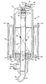
- the drawing shows an electromagnetic filter 10 that has a vertically mounted longitudinal extending cylindrical vessel 12 with an upper end 14 and a lower end 1 6.
- An access hatch 17 penetrates the upper end 14 and is sealed by a cover 18 held in place by studs 20 and nuts 21.
- the lower end 16 is penetrated by an inlet 22 and an outlet 24.
- a central pipe 26 extends longitudinally from the outlet 24 through the vessel 12.
- a cylindrical restraining screen 28 forms an extension of the central pipe 26.
- a disc or lid 30 is fixed to the screen 28 thereby directing all flow through the vessel 12 to the central pipe 26 through the screen 28.
- a knob 32 extends upwardly from the disc 30 and is engaged by a receiver 34 fixed to the upper end 14. The knob 32 however does not extend to the surface of the end 14, thereby providing allowance for a discrepancy in thermal expansion of the vessel 12 and the central pipe 26.
- An electromagnetic coil assembly 36 circumscribes the vessel 12 and rests on and is removably affixed to a support plate 39 by studs 50 and nuts 52.
- the plate 39 is affixed to the end 16 of the vessel 12.
- a structure supports the electromagnetic filter 10 at the support plate 39. This structure is readily supplied by one skilled in the art of industrial support structure and, for clarity, is not shown in the drawing.
- the coil assembly 36 is provided with lifting lugs 37 for lifting the assembly 36 off of the support plate 39 for servicing of the assembly 36. It is apparent that this may be accomplished without disturbing connections to the inlet 22 or outlet 24.
- a magnetisable filter bed 40 is disposed within the vessel 12.
- the bed 40 includes a plurality of magnetisable pellets 41.
- the pellets 41 are steel balls having a diameter of 3.18 mm (0.125 in).
- the bed 40 is supported within the vessel 12 by a support plate 38 which is an annular ring apertured to preclude the passage of pellets 41 therethrough while allowing the passage of fluid therethrough.
- Perforated annular ring flow diffusers 46 and 48 are mounted to cylindrical mounting sleeves 42 and 44 which are in turn affixed to the support plate 38. The diffusers 46 and 48 serve evently to distribute inlet fluid flow through the bed 40.
- the coil assembly 36 is energised thereby magnetising the bed 40.
- Fluid containing magnetisable impurities enters the inlet 22 in the direction of an arrow 60, flows around the central pipe 26 through the diffusers 48 and 46, and flows through the support plate 38 in the direction of the arrows 61.
- Fluid impurities are attracted to the magnetised pellets 41 and the filtered fluid (filtrate) emerges from the top of the bed 40 and flows through the screen 28 and down the central pipe 26 in the direction of arrows 62.
- the filtrate then flows through the central pipe 26 and exits via the outlet 24 in the direction of an arrow 63.
- the coil assembly 36 is removable from the filter 10 while maintaining the circulation of fluid to, through and from the vessel 12. To remove the coil assembly 36 from the filter 10, the nuts 52 are removed and the assembly 36 is simply lifted therefrom without disturbing the fluid flow.
- the area within the vessel 12 above the bed 40 is provided to enable cleaning of the bed by flushing of the filter 10.
- flushing fluid flows in a vertically upward direction within the vessel 12, generally following the direction of the arrows 61.
- the force of the upwardly flowing stream of flushing fluid is applied to the pellets or balls 41 in the bed 40 in a direction that is opposite to the gravitational force direction.
- the oppositely directed forces tend to "fluidise” and agitate the filter bed by increasing its volume and causing the individual pellet or balls 41 to separate and bounce against one another.
- Another embodiment would employ a second vessel disposed within the first.
- the second vessel would hold the bed of pellets. Liquid would enter the second vessel, flows up therethrough, pass through the bed of pellets and then down the annulus formed between the two vessels to the outlet.
- Another embodiment could employ two coil assemblies with the inlet and outlet positioned therebetween. This embodiment would enable dual flow capability.
Landscapes
- Engineering & Computer Science (AREA)
- Water Supply & Treatment (AREA)
- Chemical & Material Sciences (AREA)
- Chemical Kinetics & Catalysis (AREA)
- Filtration Of Liquid (AREA)
- Filtering Materials (AREA)
- Respiratory Apparatuses And Protective Means (AREA)
- Water Treatment By Electricity Or Magnetism (AREA)
Applications Claiming Priority (2)
| Application Number | Priority Date | Filing Date | Title |
|---|---|---|---|
| US13437280A | 1980-03-27 | 1980-03-27 | |
| US134372 | 1980-03-27 |
Publications (3)
| Publication Number | Publication Date |
|---|---|
| EP0048272A1 EP0048272A1 (en) | 1982-03-31 |
| EP0048272A4 EP0048272A4 (en) | 1982-07-30 |
| EP0048272B1 true EP0048272B1 (en) | 1984-09-12 |
Family
ID=22463074
Family Applications (1)
| Application Number | Title | Priority Date | Filing Date |
|---|---|---|---|
| EP81901068A Expired EP0048272B1 (en) | 1980-03-27 | 1981-03-23 | Removable coil electromagnetic filter |
Country Status (9)
| Country | Link |
|---|---|
| EP (1) | EP0048272B1 (enExample) |
| JP (1) | JPS594168B2 (enExample) |
| KR (1) | KR850001771B1 (enExample) |
| CA (1) | CA1158567A (enExample) |
| DE (1) | DE3165921D1 (enExample) |
| ES (1) | ES8206202A1 (enExample) |
| IT (1) | IT1135696B (enExample) |
| MX (1) | MX152794A (enExample) |
| WO (1) | WO1981002685A1 (enExample) |
Families Citing this family (6)
| Publication number | Priority date | Publication date | Assignee | Title |
|---|---|---|---|---|
| US5443719A (en) * | 1994-02-23 | 1995-08-22 | Aqua-Ion Systems, Inc. | System and reactor for mixing coagulating agents into a contaminated water flow, and for removing contaminants therefrom |
| US5635059A (en) * | 1994-10-20 | 1997-06-03 | Aqua-Ion Systems, Inc. | Method and apparatus for water treatment and purification using gas ion plasma source and disinfectant metal ion complexes |
| US5597479A (en) * | 1995-01-25 | 1997-01-28 | Aqua-Ion Systems, Inc. | Electro-coalescence/magnetic separation (ECMS) system and components for removal of contaminants from water streams, including desalinization |
| US5622622A (en) * | 1995-01-25 | 1997-04-22 | Aqua-Ion Systems, Inc. | Ultraviolet sterilizer and source of ionized molecules for electrocoalescent/magnetic separation (ECMS) removal of contaminants from water streams |
| ES2264899B1 (es) | 2005-07-12 | 2008-01-01 | Centro De Investigacion De Rotacion Y Torque Aplicada, S.L. | Filtro para capturar emisiones contaminantes. |
| CN103846159B (zh) * | 2012-11-30 | 2016-06-22 | 中国石油化工股份有限公司 | 一种固液分离装置 |
Family Cites Families (8)
| Publication number | Priority date | Publication date | Assignee | Title |
|---|---|---|---|---|
| DE478770C (de) * | 1927-11-25 | 1929-07-02 | Franz Von Wurstemberger | Verfahren zum Reinhalten elektrolytischer Baeder, insbesondere Nickelbaeder |
| GB1204324A (en) * | 1966-11-30 | 1970-09-03 | Ronald John Stevens | Improvements in and relating to filters for liquid and gaseous fluids |
| DE1277488B (de) * | 1967-06-08 | 1968-09-12 | Siemens Ag | Einrichtung zur elektromagnetischen Entfernung von Eisenoxyden aus Fluessigkeit |
| US3979288A (en) * | 1973-04-13 | 1976-09-07 | Kraftwerk Union Aktiengesellschaft | Double-flow magnetic filter, apparatus and method |
| US4054513A (en) * | 1973-07-10 | 1977-10-18 | English Clays Lovering Pochin & Company Limited | Magnetic separation, method and apparatus |
| JPS5911326B2 (ja) * | 1975-01-09 | 1984-03-14 | イングリツシユ.クレイズ.ラバ−リング.ポ−チン.アンド.Co.Ltd | 磁性粒子分離装置 |
| JPS51151868A (en) * | 1975-06-20 | 1976-12-27 | Sumitomo Metal Ind Ltd | Electromagn etic filter steel ball reviving device |
| FR2449469A1 (fr) * | 1979-02-23 | 1980-09-19 | Framatome Sa | Filtre pour l'epuration d'un fluide a haute pression et a haute temperature contenant des particules ferromagnetiques |
-
1981
- 1981-03-12 KR KR1019810000807A patent/KR850001771B1/ko not_active Expired
- 1981-03-23 WO PCT/US1981/000383 patent/WO1981002685A1/en not_active Ceased
- 1981-03-23 IT IT20663/81A patent/IT1135696B/it active
- 1981-03-23 DE DE8181901068T patent/DE3165921D1/de not_active Expired
- 1981-03-23 JP JP56501379A patent/JPS594168B2/ja not_active Expired
- 1981-03-23 EP EP81901068A patent/EP0048272B1/en not_active Expired
- 1981-03-24 ES ES500660A patent/ES8206202A1/es not_active Expired
- 1981-03-25 MX MX186539A patent/MX152794A/es unknown
- 1981-03-27 CA CA000374023A patent/CA1158567A/en not_active Expired
Also Published As
| Publication number | Publication date |
|---|---|
| MX152794A (es) | 1986-06-06 |
| JPS594168B2 (ja) | 1984-01-28 |
| DE3165921D1 (en) | 1984-10-18 |
| CA1158567A (en) | 1983-12-13 |
| ES500660A0 (es) | 1982-09-01 |
| WO1981002685A1 (en) | 1981-10-01 |
| ES8206202A1 (es) | 1982-09-01 |
| KR830004873A (ko) | 1983-07-20 |
| IT8120663A0 (it) | 1981-03-23 |
| EP0048272A1 (en) | 1982-03-31 |
| EP0048272A4 (en) | 1982-07-30 |
| KR850001771B1 (ko) | 1985-12-18 |
| JPS57500325A (enExample) | 1982-02-25 |
| IT1135696B (it) | 1986-08-27 |
Similar Documents
| Publication | Publication Date | Title |
|---|---|---|
| US2789655A (en) | Magnetic dust traps or filters | |
| EP0082925B1 (en) | Magnetic separator | |
| US20130240455A1 (en) | Magnetic Filter for Refining and Chemical Industries | |
| US3979288A (en) | Double-flow magnetic filter, apparatus and method | |
| US5055190A (en) | High volume permanent magnet filter | |
| US4432873A (en) | High gradient magnetic separation device | |
| JPH0462770B2 (enExample) | ||
| EP0048272B1 (en) | Removable coil electromagnetic filter | |
| US4280906A (en) | Filter for separating solid contaminants from a fluid, especially solid contaminants in a reactor cooling water used in nuclear reactor plants | |
| CN108262158A (zh) | 一种全自动切削液磁性过滤装置 | |
| US4750998A (en) | Desalting filtration device | |
| US4594160A (en) | Magnetizable separator for the purification of liquids | |
| US4242200A (en) | Filters for purifying fluids containing ferromagnetic particles | |
| US4244822A (en) | Industrial technique magnetic apparatus | |
| US3714037A (en) | Flocculating apparatus and method | |
| GB2061123A (en) | Filter for separating contaminant material from a fluid | |
| US4304667A (en) | Filter for purifying a fluid containing ferromagnetic particles | |
| EP0429700B1 (en) | Apparatus for the continuous purification of liquids, and in particular of water, by means of the technique of high-gradient magnetic filtration | |
| GB2228431A (en) | Electromagnetic filter with a high field gradient | |
| CA1134752A (en) | Dual-flow electromagnetic filter | |
| CA1091624A (en) | Pulsed purging of carousel-type magnetic separators | |
| SU1044310A1 (ru) | Электромагнитный фильтр-осадитель | |
| US4428836A (en) | Hydraulic discharge system | |
| SU1286246A1 (ru) | Магнитный фильтр | |
| SU1061842A1 (ru) | Электромагнитный сепаратор |
Legal Events
| Date | Code | Title | Description |
|---|---|---|---|
| PUAI | Public reference made under article 153(3) epc to a published international application that has entered the european phase |
Free format text: ORIGINAL CODE: 0009012 |
|
| 17P | Request for examination filed |
Effective date: 19811020 |
|
| AK | Designated contracting states |
Designated state(s): CH DE FR GB |
|
| GRAA | (expected) grant |
Free format text: ORIGINAL CODE: 0009210 |
|
| AK | Designated contracting states |
Designated state(s): CH DE FR GB LI |
|
| REF | Corresponds to: |
Ref document number: 3165921 Country of ref document: DE Date of ref document: 19841018 |
|
| ET | Fr: translation filed | ||
| PLBE | No opposition filed within time limit |
Free format text: ORIGINAL CODE: 0009261 |
|
| STAA | Information on the status of an ep patent application or granted ep patent |
Free format text: STATUS: NO OPPOSITION FILED WITHIN TIME LIMIT |
|
| 26N | No opposition filed | ||
| PG25 | Lapsed in a contracting state [announced via postgrant information from national office to epo] |
Ref country code: FR Free format text: LAPSE BECAUSE OF NON-PAYMENT OF DUE FEES Effective date: 19851129 |
|
| REG | Reference to a national code |
Ref country code: FR Ref legal event code: ST |
|
| PG25 | Lapsed in a contracting state [announced via postgrant information from national office to epo] |
Ref country code: LI Effective date: 19870331 Ref country code: CH Effective date: 19870331 |
|
| GBPC | Gb: european patent ceased through non-payment of renewal fee | ||
| REG | Reference to a national code |
Ref country code: CH Ref legal event code: PL |
|
| PG25 | Lapsed in a contracting state [announced via postgrant information from national office to epo] |
Ref country code: DE Effective date: 19871201 |
|
| PG25 | Lapsed in a contracting state [announced via postgrant information from national office to epo] |
Ref country code: GB Effective date: 19881118 |
|
| ITCP | It: supplementary protection certificate |
Spc suppl protection certif: CCP 363 |