EP0048238A2 - Installation for transporting elongated goods - Google Patents
Installation for transporting elongated goods Download PDFInfo
- Publication number
- EP0048238A2 EP0048238A2 EP81890144A EP81890144A EP0048238A2 EP 0048238 A2 EP0048238 A2 EP 0048238A2 EP 81890144 A EP81890144 A EP 81890144A EP 81890144 A EP81890144 A EP 81890144A EP 0048238 A2 EP0048238 A2 EP 0048238A2
- Authority
- EP
- European Patent Office
- Prior art keywords
- longitudinal
- stop
- goods
- conveyor
- tray
- Prior art date
- Legal status (The legal status is an assumption and is not a legal conclusion. Google has not performed a legal analysis and makes no representation as to the accuracy of the status listed.)
- Granted
Links
Images

Classifications
-
- B—PERFORMING OPERATIONS; TRANSPORTING
- B65—CONVEYING; PACKING; STORING; HANDLING THIN OR FILAMENTARY MATERIAL
- B65G—TRANSPORT OR STORAGE DEVICES, e.g. CONVEYORS FOR LOADING OR TIPPING, SHOP CONVEYOR SYSTEMS OR PNEUMATIC TUBE CONVEYORS
- B65G47/00—Article or material-handling devices associated with conveyors; Methods employing such devices
- B65G47/02—Devices for feeding articles or materials to conveyors
- B65G47/04—Devices for feeding articles or materials to conveyors for feeding articles
- B65G47/06—Devices for feeding articles or materials to conveyors for feeding articles from a single group of articles arranged in orderly pattern, e.g. workpieces in magazines
-
- B—PERFORMING OPERATIONS; TRANSPORTING
- B21—MECHANICAL METAL-WORKING WITHOUT ESSENTIALLY REMOVING MATERIAL; PUNCHING METAL
- B21B—ROLLING OF METAL
- B21B43/00—Cooling beds, whether stationary or moving; Means specially associated with cooling beds, e.g. for braking work or for transferring it to or from the bed
- B21B43/006—Transfer from bed
-
- B—PERFORMING OPERATIONS; TRANSPORTING
- B65—CONVEYING; PACKING; STORING; HANDLING THIN OR FILAMENTARY MATERIAL
- B65G—TRANSPORT OR STORAGE DEVICES, e.g. CONVEYORS FOR LOADING OR TIPPING, SHOP CONVEYOR SYSTEMS OR PNEUMATIC TUBE CONVEYORS
- B65G47/00—Article or material-handling devices associated with conveyors; Methods employing such devices
- B65G47/52—Devices for transferring articles or materials between conveyors i.e. discharging or feeding devices
- B65G47/53—Devices for transferring articles or materials between conveyors i.e. discharging or feeding devices between conveyors which cross one another
- B65G47/54—Devices for transferring articles or materials between conveyors i.e. discharging or feeding devices between conveyors which cross one another at least one of which is a roller-way
Definitions
- the invention relates to a device for the transport of elongated goods, in particular billets, blooms or slabs, with a storage area which accommodates the goods lying directly next to one another, which is equipped with a transverse conveyor device which transports the goods across their longitudinal extent, and with a storage device at the end of the storage area a single material receiving and moving in its longitudinal direction longitudinal conveyor.
- a device of this type is used in particular in a cooling bed from which the goods are conveyed to an oven roller table.
- the goods lie next to each other "man to man” without gaps and are moved further across the cooling bed by means of a cross conveyor designed as a pusher.
- a disadvantage of this known device is that it can only be used for particularly light goods, e.g. smaller angle profiles, is suitable and that it can not be ensured that only a single good is actually gripped by the magnetic plate.
- the invention aims to avoid these disadvantages and difficulties and has as its object to create a device of the type described at the outset, which enables a safe separation of an individual good from the "man to man” goods, etc. even if heavy goods, e.g. Sticks, blooms or slabs are to be transported, and in which no longitudinal friction occurs between the individual goods and the goods lying "man to man”.
- heavy goods e.g. Sticks, blooms or slabs
- a stop for the good is provided at a transverse distance from the end of the storage, the longitudinal conveyor provided between the end of the storage and the stop by means of an inclined guide together with a single good in an oblique direction the stop can be raised or lowered.
- the stop is designed in a step-like manner, as a result of which there is a rough lateral guide for the goods moving with the longitudinal conveyor device.
- the longitudinal conveyor is expediently formed from conveyor rollers which are arranged along a carrier and are lifted together with the carrier by means of pressure medium cylinders. and can be lowered, which ensures a uniform conveying with the longitudinal conveying device.
- a particularly space-saving design is made possible by the fact that the conveyor rollers pass through recesses in the step-shaped stop during the lifting or lowering process.
- a preferred embodiment is characterized in that the inclined guide is designed as a quadrangle, in particular as a parallelogram.
- the inclined guide is expediently designed as a slideway.
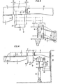
- FIG. 1 showing a view of the system in the longitudinal conveying direction
- FIG. 2 showing a plan.
- FIG. 3 illustrates, in an illustration analogous to FIG. 1, the movement sequence of the device according to the invention on an enlarged scale.
- a second embodiment is shown in Fig. 4, which also shows a view in the longitudinal conveying direction.
- a pusher 3 ensures transport in the transverse conveying direction 4, it thus represents a transverse conveying device, its drive is conventional and is not shown in the figures.
- a stop 8 attached to a longitudinal cross member 7.
- the longitudinal cross member 7 is attached by means of support arms 9 to a foundation frame 11 connected to the foundation 10.
- the longitudinal conveyor 12 is located between the end 6 of the cooling bed and the stop 8. It is formed from drivable conveyor rollers 14 located one behind the other in the longitudinal conveying direction 13, the bearings 15 of which are mounted on a double-T-shaped carrier 16, etc. at the top of this carrier.
- a drive motor 17 is provided, from which the conveyor rollers 14 are driven via chains 18 or belts.
- This support 16 can be raised and lowered by means of pressure medium cylinders 19, the pressure medium cylinders being articulated both on the support 16 and on the foundation 10 below the support.
- the foundation frame 11 forms the web of an articulated parallelogram, the carrier 16 itself represents the coupling.
- the articulated axes 21 of this articulated parallelogram extend in the longitudinal conveying direction 13.
- the rockers 20 are directed upwards by a small angle 22.
- the stick 1 'resting against the stop 8 is first lifted vertically upwards by means of the conveyor rollers, and so on. until it lies with its underside 24 exactly at the level of the upper edge 25 of the stop 8. Subsequently, by further lifting the longitudinal conveyor 12 like this, it is raised further in an oblique direction 23, so that it is in the raised position of the longitudinal conveyor, which is shown in FIG. 3 with dash-dotted lines, at a short distance 26 from the last one on the cooling bed lying stick 1 comes to lie. During this lifting, the conveyor rollers 14 ′ pass through recesses 27 in the stop 8.
- the longitudinal conveyor is raised until the billet 1 'lies approximately in the middle between the longitudinal crossmember 7, which supports the stops 8, and the last billet 1 lying on the cooling bed.
- the longitudinal cross member 7 and the last billet 1 lying on the cooling bed represent a rough lateral guide for the latter during the longitudinal conveyance of the raised billet.
- slideways 28 are provided instead of the inclined guide designed as rockers 20, along which the carrier 16 carrying the conveying rollers 14 can be moved by means of sliding rollers 29.
- the inclination of these slideways 28 is selected so that in the raised state of the longitudinal conveyor the billet is again centered between the last billet 1 located on the cooling bed and the longitudinal cross member 7.
- the invention is not limited to the exemplary embodiments shown in the drawing, but can be modified in various ways. For example it is possible to "separate" the goods by lowering the longitudinal conveyor.
- the device according to the invention can be used wherever a transverse material flow has to be deflected into a longitudinal material flow, for example on rolling mills, etc.
Landscapes
- Engineering & Computer Science (AREA)
- Mechanical Engineering (AREA)
- Attitude Control For Articles On Conveyors (AREA)
- Heat Treatments In General, Especially Conveying And Cooling (AREA)
- Reciprocating Conveyors (AREA)
Abstract
Description
Die Erfindung betrifft eine Einrichtung zum Transport von langgestreckten Gütern, insbesondere Knüppel, Blooms oder Brammen, mit einer die unmittelbar nebeneinanderliegenden Güter aufnehmenden Ablage, die mit einer die Güter quer zu ihrer Längserstreckung fördernden Quer-Fördereinrichtung ausgestattet ist, und mit einer am Ende der Ablage ein einzelnes Gut aufnehmenden und in seiner Längsrichtung bewegenden Längs-Fördereinrichtung.The invention relates to a device for the transport of elongated goods, in particular billets, blooms or slabs, with a storage area which accommodates the goods lying directly next to one another, which is equipped with a transverse conveyor device which transports the goods across their longitudinal extent, and with a storage device at the end of the storage area a single material receiving and moving in its longitudinal direction longitudinal conveyor.
Eine Einrichtung dieser Art kommt insbesondere bei einem Kühlbett in Verwendung, von dem aus die Güter auf einen Ofenrollgang befördert werden. Die Güter liegen-dabei ohne Zwischenräume nebeneinander "Mann an Mann" und werden über das Kühlbett mittels einer als Abschieber ausgebildeten Quer-Fördereinrichtung in Querrichtung weiterbewegt.A device of this type is used in particular in a cooling bed from which the goods are conveyed to an oven roller table. The goods lie next to each other "man to man" without gaps and are moved further across the cooling bed by means of a cross conveyor designed as a pusher.
Will man nun ein einzelnes Gut zum Ofenrollgang in Längsrichtung bewegen, so steht man vor dem Problem, daß die "Mann an Mann" liegenden Güter aneinander infolge Berührung hängenbleiben und die Reibungsverhältnisse der Längs-Fördereinrichtung oft nicht ausreichen, um ein einzelnes Gut von den "Mann an Mann" liegenden Gütern wegzubewegen. Es kommt hierbei oftmals zu Betriebsstörungen.If you now want to move a single good to the oven roller table in the longitudinal direction, you are faced with the problem that the "hand to hand" goods stick to one another as a result of contact and the frictional conditions of the longitudinal conveyor device are often insufficient to separate a single good from the " Man to man "moving away lying goods. This often leads to malfunctions.
Um solche Betriebsstörungen zu vermeiden ist es bekannt (DE-OS 1 452 147) ein einzelnes Gut von den "Mann an Mann" liegenden Gütern mittels einer schwenkbaren Magnetplatte wegzubewegen und mit einem Ende zu einem Rollgang zu fördern, welcher Bewegungsablauf von Schwenkarmen, die dieses weggeschwenkte Gut untergreifen, unterstützt wird.In order to avoid such malfunctions, it is known (DE-OS 1 452 147) to move a single good away from the "man to man" goods by means of a swiveling magnetic plate and with one end towards a roller table promote which movement sequence is supported by swivel arms that reach under this swung-away material.
Ein Nachteil dieser bekannten Einrichtung ist darin zu sehen, daß sie nur für besonders leichtes Gut, wie z.B. kleinere Winkelprofile,geeignet ist und daß es nicht sichergestellt werden kann, daß jeweils tatsächlich nur ein einzelnes Gut von der Magnetplatte erfaßt wird.A disadvantage of this known device is that it can only be used for particularly light goods, e.g. smaller angle profiles, is suitable and that it can not be ensured that only a single good is actually gripped by the magnetic plate.
Die Erfindung bezweckt die Vermeidung dieser Nachteile und Schwierigkeiten und stellt sich die Aufgabe eine Einrichtung der eingangs bezeichneten Art zu schaffen, die ein sicheres Trennen eines einzelnen Gutes von den "Mann an Mann" liegenden Gütern ermöglicht, u.zw. auch dann, wenn schwere Güter, wie z.B. Knüppel, Blooms oder Brammen, transportiert werden sollen,und bei der beim Längsfördern des einzelnen Gutes keine Reibung zwischen diesem und den "Mann an Mann" liegenden Gütern auftritt.The invention aims to avoid these disadvantages and difficulties and has as its object to create a device of the type described at the outset, which enables a safe separation of an individual good from the "man to man" goods, etc. even if heavy goods, e.g. Sticks, blooms or slabs are to be transported, and in which no longitudinal friction occurs between the individual goods and the goods lying "man to man".
Diese Aufgabe wird erfindungsgemäß dadurch gelöst, daß im Quer-Abstand vom Ende der Ablage ein Anschlag für das Gut vorgesehen ist, wobei die zwischen dem Ende der Ablage und dem Anschlag vorgesehene Längs-Fördereinrichtung mittels einer Schrägführung zusammen mit einem einzelnen Gut in schräger Richtung über den Anschlag hinaus heb- bzw. senkbar ist.This object is achieved in that a stop for the good is provided at a transverse distance from the end of the storage, the longitudinal conveyor provided between the end of the storage and the stop by means of an inclined guide together with a single good in an oblique direction the stop can be raised or lowered.
Nach einer bevorzugten Ausführungsform ist der Anschlag stufenförmig ausgebildet, wodurch eine grobe Seitenführung für das mit der Längs-Fördereinrichtung bewegte Gut vorhanden ist.According to a preferred embodiment, the stop is designed in a step-like manner, as a result of which there is a rough lateral guide for the goods moving with the longitudinal conveyor device.
Zweckmäßig ist die Längs-Fördereinrichtung aus längs eines Trägers angeordneten Förderrollen gebildet, die mit dem Träger gemeinsam mittels Druckmittelzylinder heb-und senkbar sind, wodurch ein gleichmäßiges Fördern mit der Längs-Fördereinrichtung sichergestellt ist.The longitudinal conveyor is expediently formed from conveyor rollers which are arranged along a carrier and are lifted together with the carrier by means of pressure medium cylinders. and can be lowered, which ensures a uniform conveying with the longitudinal conveying device.
Eine besonders platzsparende Bauweise wird dadurch ermöglicht, daß die Förderrollen Ausnehmungen des stufenförmigen Anschlags während des Heb- bzw. Senkvorganges durchsetzen.A particularly space-saving design is made possible by the fact that the conveyor rollers pass through recesses in the step-shaped stop during the lifting or lowering process.
Eine bevorzugte Ausführungsform ist dadurch gekennzeichnet, daß die Schrägführung als Gelenkviereck, insbesondere als Gelenkparallelogramm ausgebildet ist.A preferred embodiment is characterized in that the inclined guide is designed as a quadrangle, in particular as a parallelogram.
Gemäß einer weiteren Ausführungsform ist zweckmäßig die Schrägführung als Gleitbahn ausgebildet.According to a further embodiment, the inclined guide is expediently designed as a slideway.
Die Erfindung ist nachstehend anhand der Zeichnung an zwei Ausführungsformen näher erläutert, wobei Fig. 1 eine Ansicht der Anlage in Längs-Förderrichtung und Fig. 2 einen Grundriß zeigen. Fig. 3 veranschaulicht in zu Fig. 1 analoger Darstellung den Bewegungsablauf der erfindungsgemäßen Einrichtung in vergrößertem Maßstab. Eine zweite Ausführungsform ist in Fig. 4, die ebenfalls eine Ansicht in Längs-Förderrichtung zeigt, dargestellt.The invention is explained in more detail below with reference to the drawing in two embodiments, FIG. 1 showing a view of the system in the longitudinal conveying direction and FIG. 2 showing a plan. FIG. 3 illustrates, in an illustration analogous to FIG. 1, the movement sequence of the device according to the invention on an enlarged scale. A second embodiment is shown in Fig. 4, which also shows a view in the longitudinal conveying direction.
Die "Mann an Mann" gereihten Güter 1, 1'- bei dem dargestellten Ausführungsbeispiel handelt es sich um Knüppelliegen auf Querträgern 2 auf, die ein Kühlbett bilden. Ein Abschieber 3 sorgt für den Transport in Quer-Förderrichtung 4, er stellt somit eine Quer-Fördereinrichtung dar, sein Antrieb ist konventionell und in den Fig. nicht dargestellt. Im Quer-Abstand 5 vom Ende 6 des Kühlbettes befindet sich ein an einer Längstraverse 7 befestigter Anschlag 8. Die Längstraverse 7 ist mittels Stützarmen 9 an einem mit dem Fundament 10 verbundenen Fundamentrahmen 11 befestigt. Zwischen dem Ende 6 des Kühlbettes und dem Anschlag 8 befindet sich die Längs-Fördereinrichtung 12. Sie wird aus in Längs-Förderrichtung 13 hintereinanderliegenden antreibbaren Förderrollen 14 gebildet, deren Lager 15 an einem doppel-T-förmigen Träger 16 montiert sind, u.zw. an der Oberseite dieses Trägers. An der Unterseite dieses Trägers 16 ist ein Antriebsmotor 17 vorgesehen, von dem aus die Förderrollen 14 über Ketten 18 oder Riemen angetrieben werden.The "man to man"
Dieser Träger 16 ist mittels Druckmittelzylinder 19 heb-und senkbar, wobei die Druckmittelzylinder sowohl am Träger 16 als auch am Fundament 10 unterhalb des Trägers angelenkt sind. Zur Führung des Trägers 16 ist dieser mittels zweier Schwingen 20 am Fundamentrahmen 11 angelenkt. Der Fundamentrahmen 11 bildet dabei den Steg eines Gelenkparallelogramms, der Träger 16 selbst stellt die Koppel dar. Die Gelenkachsen 21 dieses Gelenkparallelogramms erstrecken sich in Längs-Förderrichtung 13. Befinden sich die Förderrollen 14 in Höhe des Kühlbettes, d.h. in abgesenkter Position (Fig. 1), so sind die Schwingen 20 um einen geringen Winkel 22 nach oben gerichtet.This
Die Funktion der Einrichtung ist folgende:
- Die auf dem Kühlbett
liegenden Knüppel 1, 1' werden mittels desAbschiebers 2 in Quer-Förderrichtung 4 zur Längs-Fördereinrichtung 12, derenFörderrollen 14 sich in abgesenkter Position, wie in Fig. 1 dargestellt, befinden, gefördert. Der dort als erster ankommende Knüppel 1' wird durch denAnschlag 8 gestoppt. DerAbschieber 2 wird nach dem Stoppen des Knüppels 1' stillgesetzt. Anschließend wird die Längs-Fördereinrichtung 12 mittels derDruckmittelzylinder 19 gehoben, wobei infolge der besonderen Anordnung derSchwingen 20 die Längs-Fördereinrichtung inschräger Richtung 23 nach oben bewegt wird. DieSchwingen 20 stellen demnach eine Schrägführung für die Längs-Fördereinrichtung 12 dar.
- The
billets 1, 1 'lying on the cooling bed are conveyed by means of thepusher 2 in thetransverse conveying direction 4 to thelongitudinal conveying device 12, theconveying rollers 14 of which are in the lowered position, as shown in FIG. 1. The billet 1 'arriving there first is stopped by thestop 8. Thepusher 2 is stopped after the stick 1 'has stopped. Thelongitudinal conveyor device 12 is then lifted by means of thepressure medium cylinders 19, the longitudinal conveyor device being moved upwards in anoblique direction 23 due to the special arrangement of therockers 20. Therockers 20 therefore represent an inclined guide for thelongitudinal conveyor device 12.
Wie insbesondere aus Fig. 3 ersichtlich ist, wird der am Anschlag 8 anliegende Knüppel 1' mittels der Förderrollen zunächst vertikal nach oben gehoben, u.zw. solange, bis er mit seiner Unterseite 24 genau in Höhe der Oberkante 25 des Anschlags 8 liegt. Anschließend daran wird er durch weiteres Anheben der Längs-Fördereinrichtung 12 wie diese in schräger Richtung 23 weitergehoben, sodaß er in angehobener Stellung der Längs-Fördereinrichtung, die in Fig. 3 mit strichpunktierten Linien dargestellt ist, in geringem Abstand 26 vom letzten noch am Kühlbett liegenden Knüppel 1 zu liegen kommt. Die Förderrollen 14'durchsetzen bei diesem Hochheben Ausnehmungen 27 des Anschlages 8.As can be seen in particular from FIG. 3, the stick 1 'resting against the
Wie aus Fig. 3 weiters ersichtlich ist, wird die Längs-Fördereinrichtung soweit gehoben, bis der Knüppel 1' etwa mittig zwischen der Längstraverse 7, die die Anschläge 8 trägt, und dem letzten am Kühlbett liegenden Knüppel 1 liegt. Die Längstraverse 7 und der letzte am Kühlbett liegende Knüppel 1 stellen während des Längsförderns des hochgehobenen Knüppels eine grobe Seitenführung für diesen dar.As can also be seen from FIG. 3, the longitudinal conveyor is raised until the billet 1 'lies approximately in the middle between the
Bei der in Fig. 4 dargestellten Ausführungsform sind anstelle der als Schwingen 20 ausgebildeten Schrägführung Gleitbahnen 28 vorgesehen, entlang denen der die Förderrollen 14 tragende Träger 16 mittels Gleitrollen 29 bewegbar ist. Die Neigung dieser Gleitbahnen 28 ist so gewählt, daß im angehobenen Zustand der Längs-Fördereinrichtung der Knüppel wieder mittig zwischen dem letzten auf dem Kühlbett befindlichen Knüppel 1 und der Längstraverse 7 liegt.In the embodiment shown in FIG. 4,
Die Erfindung beschränkt sich nicht auf die in der Zeichnung dargestellten Ausführungsbeispiele, sondern kann in verschiedener Hinsicht modifiziert werden. Beispielsweise ist es möglich, auch durch Absenken der Längs-Fördereinrichtung eine "Vereinzelung" der Güter zu erreichen.The invention is not limited to the exemplary embodiments shown in the drawing, but can be modified in various ways. For example it is possible to "separate" the goods by lowering the longitudinal conveyor.
Weiters kann die erfindungsgemäße Einrichtung überall dort angewendet werden, wo ein Quer-Materialfluß in einen Längs-Materialfluß umgelenkt werden muß, beispielsweise bei Walzstraßen, etc.Furthermore, the device according to the invention can be used wherever a transverse material flow has to be deflected into a longitudinal material flow, for example on rolling mills, etc.
Claims (6)
Applications Claiming Priority (2)
| Application Number | Priority Date | Filing Date | Title |
|---|---|---|---|
| AT4567/80 | 1980-09-11 | ||
| AT0456780A AT367714B (en) | 1980-09-11 | 1980-09-11 | DEVICE FOR THE TRANSPORT OF LONG-STRETCHED GOODS |
Publications (3)
| Publication Number | Publication Date |
|---|---|
| EP0048238A2 true EP0048238A2 (en) | 1982-03-24 |
| EP0048238A3 EP0048238A3 (en) | 1982-05-12 |
| EP0048238B1 EP0048238B1 (en) | 1985-01-02 |
Family
ID=3565636
Family Applications (1)
| Application Number | Title | Priority Date | Filing Date |
|---|---|---|---|
| EP19810890144 Expired EP0048238B1 (en) | 1980-09-11 | 1981-08-26 | Installation for transporting elongated goods |
Country Status (4)
| Country | Link |
|---|---|
| EP (1) | EP0048238B1 (en) |
| JP (1) | JPS5781011A (en) |
| AT (1) | AT367714B (en) |
| DE (1) | DE3168040D1 (en) |
Cited By (2)
| Publication number | Priority date | Publication date | Assignee | Title |
|---|---|---|---|---|
| CN109926600A (en) * | 2019-04-08 | 2019-06-25 | 安庆帝伯粉末冶金有限公司 | A kind of valve retainer arranging-in-row device |
| CN113430348A (en) * | 2021-06-30 | 2021-09-24 | 南京钢铁股份有限公司 | Automatic feed divider of full-automatic cutting board production |
Citations (6)
| Publication number | Priority date | Publication date | Assignee | Title |
|---|---|---|---|---|
| US2896796A (en) * | 1957-11-04 | 1959-07-28 | Blaw Knox Co | Pipe lowering device |
| DE1110116B (en) * | 1955-12-14 | 1961-07-06 | Schloemann Ag | Device for transferring elongated rolling stock from an approximately horizontal-right screen grate onto a slide |
| DE1258792B (en) * | 1962-04-27 | 1968-01-11 | Davy & United Eng Co Ltd | Method and device for laterally moving apart and separating out elongated square objects |
| DE1261060B (en) * | 1961-10-06 | 1968-02-08 | Electrolux Ab | Device for the individual transfer of packages |
| DE1452147A1 (en) * | 1965-09-04 | 1969-04-24 | Verwaltungsgesellschaft Moelle | Device for the transverse conveying of individual roll bars, especially profile bars, from closely spaced groups |
| US3605981A (en) * | 1966-10-07 | 1971-09-20 | Luigi Danieli | Device for transferring bars from the cooling bed of a hot rolling mill for conveyance on a transport roller path |
-
1980
- 1980-09-11 AT AT0456780A patent/AT367714B/en not_active IP Right Cessation
-
1981
- 1981-08-26 EP EP19810890144 patent/EP0048238B1/en not_active Expired
- 1981-08-26 DE DE8181890144T patent/DE3168040D1/en not_active Expired
- 1981-09-08 JP JP14041481A patent/JPS5781011A/en active Pending
Patent Citations (6)
| Publication number | Priority date | Publication date | Assignee | Title |
|---|---|---|---|---|
| DE1110116B (en) * | 1955-12-14 | 1961-07-06 | Schloemann Ag | Device for transferring elongated rolling stock from an approximately horizontal-right screen grate onto a slide |
| US2896796A (en) * | 1957-11-04 | 1959-07-28 | Blaw Knox Co | Pipe lowering device |
| DE1261060B (en) * | 1961-10-06 | 1968-02-08 | Electrolux Ab | Device for the individual transfer of packages |
| DE1258792B (en) * | 1962-04-27 | 1968-01-11 | Davy & United Eng Co Ltd | Method and device for laterally moving apart and separating out elongated square objects |
| DE1452147A1 (en) * | 1965-09-04 | 1969-04-24 | Verwaltungsgesellschaft Moelle | Device for the transverse conveying of individual roll bars, especially profile bars, from closely spaced groups |
| US3605981A (en) * | 1966-10-07 | 1971-09-20 | Luigi Danieli | Device for transferring bars from the cooling bed of a hot rolling mill for conveyance on a transport roller path |
Cited By (3)
| Publication number | Priority date | Publication date | Assignee | Title |
|---|---|---|---|---|
| CN109926600A (en) * | 2019-04-08 | 2019-06-25 | 安庆帝伯粉末冶金有限公司 | A kind of valve retainer arranging-in-row device |
| CN109926600B (en) * | 2019-04-08 | 2023-12-01 | 安庆帝伯粉末冶金有限公司 | Valve seat ring alignment device |
| CN113430348A (en) * | 2021-06-30 | 2021-09-24 | 南京钢铁股份有限公司 | Automatic feed divider of full-automatic cutting board production |
Also Published As
| Publication number | Publication date |
|---|---|
| ATA456780A (en) | 1981-12-15 |
| AT367714B (en) | 1982-07-26 |
| JPS5781011A (en) | 1982-05-20 |
| EP0048238B1 (en) | 1985-01-02 |
| DE3168040D1 (en) | 1985-02-14 |
| EP0048238A3 (en) | 1982-05-12 |
Similar Documents
| Publication | Publication Date | Title |
|---|---|---|
| DE3107495C2 (en) | ||
| EP0709316B1 (en) | Delivery apparatus for articles arriving in transverse rows on a circulating endless feed belt | |
| DE1781097B2 (en) | AUTOMATIC SYSTEM FOR CONVEYING TROUGH-SHAPED PALLETS WITH A TRANSPORT ROLLER CONVEYOR | |
| DE3705561C1 (en) | Conveyor device | |
| EP1667907B1 (en) | System for loading and unloading unit loads into and from a cargo hold, in particular of an aircraft | |
| EP2186756B1 (en) | Horizontal transporter for transporting piece goods | |
| EP0059984A2 (en) | Distributing device for a conveyor | |
| DE2355143C3 (en) | Pallet transfer device | |
| DE4040795C1 (en) | ||
| EP0664262A1 (en) | Tiltable conveyor part for an article conveyor (sorter) | |
| DE2122990C3 (en) | Machine for processing the edges of glass panes or the like. | |
| DE3505597C2 (en) | Device for the formation of spaced successive transverse rows of filled waffle cuts, oriented transversely to the transport direction | |
| DE3125885C2 (en) | Deflection device for piece goods | |
| EP0048238B1 (en) | Installation for transporting elongated goods | |
| DE102014010556B4 (en) | Drive car for a transport device and transport system | |
| DE19532641A1 (en) | Device for moving container, especially on rack feeder | |
| EP0371232B1 (en) | Method for the stepped grouping of products, and device for carrying out this method | |
| DE3208801A1 (en) | Switch for belt conveyor for waffle blocks and the like | |
| EP0010548B1 (en) | Intermittently operating direction changer rotatable in a horizontal plane | |
| EP0157290B1 (en) | Apparatus for making shaped chocolate articles | |
| DE2727938C2 (en) | Conveyor device with roller table and cross conveyor | |
| EP0597386B1 (en) | Arrangement for transferring metal sheets in a press plant | |
| DE19506480A1 (en) | Appts. for loading and unloading trolley contg. suspended foods | |
| DE3403215A1 (en) | Device for discharging piles of paper from a conveying line | |
| DE1005904B (en) | Device for stacking surface-sensitive sheets |
Legal Events
| Date | Code | Title | Description |
|---|---|---|---|
| PUAI | Public reference made under article 153(3) epc to a published international application that has entered the european phase |
Free format text: ORIGINAL CODE: 0009012 |
|
| PUAL | Search report despatched |
Free format text: ORIGINAL CODE: 0009013 |
|
| AK | Designated contracting states |
Designated state(s): BE CH DE FR GB IT LU NL SE |
|
| AK | Designated contracting states |
Designated state(s): BE CH DE FR GB IT LU NL SE |
|
| 17P | Request for examination filed |
Effective date: 19820927 |
|
| ITF | It: translation for a ep patent filed |
Owner name: SOCIETA' ITALIANA BREVETTI S.P.A. |
|
| GRAA | (expected) grant |
Free format text: ORIGINAL CODE: 0009210 |
|
| AK | Designated contracting states |
Designated state(s): BE CH DE FR GB IT LI LU NL SE |
|
| PG25 | Lapsed in a contracting state [announced via postgrant information from national office to epo] |
Ref country code: NL Effective date: 19850102 |
|
| REF | Corresponds to: |
Ref document number: 3168040 Country of ref document: DE Date of ref document: 19850214 |
|
| ET | Fr: translation filed | ||
| NLV1 | Nl: lapsed or annulled due to failure to fulfill the requirements of art. 29p and 29m of the patents act | ||
| PG25 | Lapsed in a contracting state [announced via postgrant information from national office to epo] |
Ref country code: LU Free format text: LAPSE BECAUSE OF NON-PAYMENT OF DUE FEES Effective date: 19850831 |
|
| PLBE | No opposition filed within time limit |
Free format text: ORIGINAL CODE: 0009261 |
|
| STAA | Information on the status of an ep patent application or granted ep patent |
Free format text: STATUS: NO OPPOSITION FILED WITHIN TIME LIMIT |
|
| 26N | No opposition filed | ||
| PG25 | Lapsed in a contracting state [announced via postgrant information from national office to epo] |
Ref country code: SE Effective date: 19860827 |
|
| PG25 | Lapsed in a contracting state [announced via postgrant information from national office to epo] |
Ref country code: LI Effective date: 19860831 Ref country code: CH Effective date: 19860831 |
|
| BERE | Be: lapsed |
Owner name: VOEST-ALPINE A.G. Effective date: 19860831 |
|
| GBPC | Gb: european patent ceased through non-payment of renewal fee | ||
| PG25 | Lapsed in a contracting state [announced via postgrant information from national office to epo] |
Ref country code: FR Free format text: LAPSE BECAUSE OF NON-PAYMENT OF DUE FEES Effective date: 19870430 |
|
| REG | Reference to a national code |
Ref country code: CH Ref legal event code: PL |
|
| PG25 | Lapsed in a contracting state [announced via postgrant information from national office to epo] |
Ref country code: DE Effective date: 19870501 |
|
| REG | Reference to a national code |
Ref country code: FR Ref legal event code: ST |
|
| PG25 | Lapsed in a contracting state [announced via postgrant information from national office to epo] |
Ref country code: GB Effective date: 19881118 |
|
| PG25 | Lapsed in a contracting state [announced via postgrant information from national office to epo] |
Ref country code: BE Effective date: 19890831 |
|
| EUG | Se: european patent has lapsed |
Ref document number: 81890144.9 Effective date: 19870812 |