EP0047664B1 - Improvements in or relating to apparatus for reacting chemicals - Google Patents
Improvements in or relating to apparatus for reacting chemicals Download PDFInfo
- Publication number
- EP0047664B1 EP0047664B1 EP81304097A EP81304097A EP0047664B1 EP 0047664 B1 EP0047664 B1 EP 0047664B1 EP 81304097 A EP81304097 A EP 81304097A EP 81304097 A EP81304097 A EP 81304097A EP 0047664 B1 EP0047664 B1 EP 0047664B1
- Authority
- EP
- European Patent Office
- Prior art keywords
- diaphragm
- crucible
- retort
- magnesium
- zrc1
- Prior art date
- Legal status (The legal status is an assumption and is not a legal conclusion. Google has not performed a legal analysis and makes no representation as to the accuracy of the status listed.)
- Expired
Links
Images
Classifications
-
- C—CHEMISTRY; METALLURGY
- C22—METALLURGY; FERROUS OR NON-FERROUS ALLOYS; TREATMENT OF ALLOYS OR NON-FERROUS METALS
- C22B—PRODUCTION AND REFINING OF METALS; PRETREATMENT OF RAW MATERIALS
- C22B34/00—Obtaining refractory metals
- C22B34/10—Obtaining titanium, zirconium or hafnium
- C22B34/14—Obtaining zirconium or hafnium
-
- C—CHEMISTRY; METALLURGY
- C22—METALLURGY; FERROUS OR NON-FERROUS ALLOYS; TREATMENT OF ALLOYS OR NON-FERROUS METALS
- C22B—PRODUCTION AND REFINING OF METALS; PRETREATMENT OF RAW MATERIALS
- C22B5/00—General methods of reducing to metals
- C22B5/02—Dry methods smelting of sulfides or formation of mattes
- C22B5/04—Dry methods smelting of sulfides or formation of mattes by aluminium, other metals or silicon
Definitions
- This invention relates to apparatus for reacting chemicals.
- Patent Specification GB-A-1013887 an apparatus for reacting chemicals has been disclosed, which comprises a retort means, containing a first reactant, a crucible means, containing a second reactant, a passage means interconnecting the retort and crucible, a heating means, a closure means, and a means for opening the closure means to effect interaction between the reactants.
- apparatus for reacting chemicals comprises retort means for containing a first reactant; crucible means for containing a second reactant; passage means interconnecting the retort means and the crucible means; means for heating at least one of the reactants to a predetermined temperature; wall means between the retort means and crucible means for transmitting heat therebetween by radiation; closure means in the passage means for preventing interaction between the reactants and including a diaphragm extending across the passage means in a fluid-tight manner; and means for opening the closure means to effect interreaction of the reactants at the predetermined temperature and including cutter means for movement against and severance of the diaphragm.
- the invention also includes a process for reaction of ZrC1 4 with magnesium, characterized in that said process is performed in an apparatus according to any of claims 1 to 5, the ZrC1 4 being contained in said retort and the magnesium in said crucible.
- the advantage of the apparatus and process of this invention is that the intended product, for example, zirconium sponge, contains a minimal amount of side products and impurities.
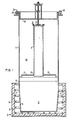
- apparatus for reducing a metal compound to elemental metal comprises a crucible 5, a retort 7, opening means or conduit 9, and a furnace 11.
- the apparatus 3 is preferably used as a reduction plant for reacting zirconium tetrachloride with elemental magnesium to form zirconium sponge and magnesium chloride, the apparatus may be used for the conversion of other reactants requiring similar reacting conditions as set forth below, notably titanium.
- the crucible 5 in which the reaction occurs is a cup-shaped receptacle and may have an inside liner of, for example, stainless steel (not shown). Elemental magnesium 13 in the form of pigs or particles is disposed in the crucible.
- the crucible 5 is located in the furnace 11 having an insulative liner 15 and spaced heating elements 17. The purpose of the furnace 11 is to maintain the magnesium 13 in a molten state in a temperature range of from 650°C to 700°C, which includes the melting point of magnesium of 651°C.
- the retort 7 is a cylindrical member in registry with the crucible 5 and usually having its lower end secured to the upper end of the crucible 5 by a peripheral weld 19 to ensure an air-tight atmosphere within the crucible 5.
- the retort 7 includes a bottom wall 21 and a cover 23 which by suitable means, such as spaced bolts 25, is secured in an air-tight manner on an upper peripheral flange 27 of the retort.
- conduit 9 Communication between the retort 7 and the crucible 5 is provided by the passageway or conduit 9 which is substantially centrally situated in the retort 7 and the lower end of which is secured by a welded joint 29 in the bottom wall 21.
- the upper end of the conduit 9 comprises closure means generally indicated at 31 which is detachable to enable opening of the conduit 9 when proper temperature conditions are obtained.
- the closure means 31 comprises a diaphragm 33 of metal, such as light gauge steel.
- the diaphragm 33 is secured tightly in place around the periphery at the upper end of the conduit 9 between a peripheral flange 35 mounted at the upper end of the conduit and a clamping ring 37 which is secured in place by suitable means, such as spaced bolts 39.
- the flange 35 and the ring 37 include mutually interfitting tongue and groove members 41, 42, respectively, for securing the peripheral portion of the diaphragm 33 tightly in place.
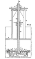
- Means for opening the closure means 31 to enable interaction of the reactants in the retort 7 and the crucible 5 are generally indicated at 45 (Fig. 2).
- the means 45 comprises a circular knife or blade 47 and lifting means generally indicated at 49 (Fig. 2).
- the blade 47 is an annulus having an upper cutting edge 51 facing the undersurface of the diaphragm 33. When the blade 47 is raised, the diaphragm 33 being clamped between the tongue and groove 41, 42 at the periphery and a similar tongue and groove 53, 55 in a hub assembly 57, is severed, whereby the closure means 31 is broken and permits communication between the retort 7 and the crucible 5.
- the lifting means 49 comprises an elongated tube 59 and a nut 61.
- the lifting means is supported on an elevated platform 63 supported on spaced upright 65 extending from the cover 23.
- the upper end portion of the tube 59 is threaded at 67 which thread is engaged by a thread 69 on the nut 61.
- the nut includes radially extending handles 71 by which the nut 61 is turned to raise and lower the tube 59, whereby the blade 57 is raised and lowered to and from the diaphragm 33.
- the hub assembly 57 is secured to the lower end of the tube 59 and comprises a hub 73 and a clamping plate 75 which are secured together by suitable means such as a plurality of bolts 77. As shown in Fig. 2, the tongue and groove 53, 55 are disposed in the hub 73 and plate 75, respectively, for securing the inner periphery of the diaphragm 33 tightly in place.
- the annular blade 47 is secured in place by spokes 79 which extend radially from the hub 73. In the retracted position, the blade 47 is supported on blocks 81 on the inner surface of the conduit 9.
- the tube 59 is open at the upper end to enable introduction of an inert gas, such as helium or argon, as indicated by an arrow 83 which gas moves out of the lower end of the tube 59 and into the conduit 9 from where it moves into the crucible 13.
- an inert gas such as helium or argon
- a gas-tight joint is provided between the cover 23 and the tube 59 which joint includes a tube 85 and a gasket nut 87.
- the nut 87 is secured to the upper end of the tube 85 by a gas tight joint 87, such as a threaded joint, and is slidably mounted on the outer surface of the tube 59 by a gas-tight joint 91.
- the magnesium 13 in the crucible 5 is melted, heat radiates through the retort bottom wall 21 (Fig. 1) as well as through the conduit 9 to vaporize a mass 93 of zirconium tetrachloride (ZrC1 4 ) within the retort 7.
- the ZrCl 4 is preferably in powdered form and vaporizes at about 331°C. As the volume of the vapor increases, it fills the chamber of the retort 7 where it is confined until all of the magnesium metal 13 is completely melted at about 700°C, when the conditions are conducive to a satisfactory reaction between the magnesium and the zirconium tetrachloride vapor. As the seal between these reactants is severed by cutting the diaphragm 33, the vapor descends through the conduit 9 into the crucible 5. The resulting reaction is in accordance with the formula:
- the resulting zirconium is in the form of zirconium sponge which settles to the bottom of the crucible 5 with any remaining magnesium and magnesium chloride being disposed above a resulting body of zirconium sponge.
- the apparatus of this invention provide means for producing zirconium sponge with the resulting formation of magnesium chloride and thereby avoiding the formation of subchlorides, such as ZrCl 2 , which form at lower temperatures than in the temperatures range of 650° to 700°C. It is necessary to avoid the formation of such subchlorides because of their highly pyrophoric characteristics and thereby avoid a fire hazard which is a constant consideration throughout the process of reducing zirconium from the zirconium chloride to the elemental state. Finally, it is emphasized that magnesium is completely melted before the reaction commences so that the pyrophoric zirconium dichloride formation is avoided.
- subchlorides such as ZrCl 2
Landscapes
- Engineering & Computer Science (AREA)
- Chemical & Material Sciences (AREA)
- Manufacturing & Machinery (AREA)
- Materials Engineering (AREA)
- Mechanical Engineering (AREA)
- Metallurgy (AREA)
- Organic Chemistry (AREA)
- Manufacture And Refinement Of Metals (AREA)
- Muffle Furnaces And Rotary Kilns (AREA)
Applications Claiming Priority (2)
| Application Number | Priority Date | Filing Date | Title |
|---|---|---|---|
| US184686 | 1980-09-08 | ||
| US06/184,686 US4440384A (en) | 1980-09-08 | 1980-09-08 | Retort pipe seal |
Publications (2)
| Publication Number | Publication Date |
|---|---|
| EP0047664A1 EP0047664A1 (en) | 1982-03-17 |
| EP0047664B1 true EP0047664B1 (en) | 1986-04-16 |
Family
ID=22677944
Family Applications (1)
| Application Number | Title | Priority Date | Filing Date |
|---|---|---|---|
| EP81304097A Expired EP0047664B1 (en) | 1980-09-08 | 1981-09-08 | Improvements in or relating to apparatus for reacting chemicals |
Country Status (5)
| Country | Link |
|---|---|
| US (1) | US4440384A (cg-RX-API-DMAC10.html) |
| EP (1) | EP0047664B1 (cg-RX-API-DMAC10.html) |
| JP (1) | JPS5779131A (cg-RX-API-DMAC10.html) |
| CA (1) | CA1169232A (cg-RX-API-DMAC10.html) |
| DE (1) | DE3174403D1 (cg-RX-API-DMAC10.html) |
Families Citing this family (1)
| Publication number | Priority date | Publication date | Assignee | Title |
|---|---|---|---|---|
| US5049363A (en) * | 1989-08-03 | 1991-09-17 | Westinghouse Electric Corp. | Recovery of scandium, yttrium and lanthanides from titanium ore |
Family Cites Families (15)
| Publication number | Priority date | Publication date | Assignee | Title |
|---|---|---|---|---|
| GB552234A (en) * | 1942-02-03 | 1943-03-29 | Int Alloys Ltd | Apparatus for use in distilling metals by electric induction heating |
| DE1138552B (de) * | 1943-03-03 | 1962-10-25 | Helmut Von Zeppelin Dr Ing | Verfahren zur Reduktion fluechtiger Halogenide und Gewinnung schwierig schmelzbarer Metalle und deren Legierungen |
| US2375199A (en) * | 1944-04-26 | 1945-05-08 | Metal Hydrides Inc | Purification of metals |
| FR1042104A (fr) * | 1950-09-13 | 1953-10-29 | Nat Smelting Co Ltd | Perfectionnements apportés à la préparation de métaux par réduction de leurs halogénures métalliques |
| US3158671A (en) * | 1954-08-12 | 1964-11-24 | Montedison Spa | Apparatus for producing titanium sponge |
| US3039866A (en) * | 1957-03-06 | 1962-06-19 | Res Inst Iron Steel | Method of manufacturing crystallized titanium of high purity and an apparatus for carrying out the method |
| US2997385A (en) * | 1958-10-29 | 1961-08-22 | Du Pont | Method of producing refractory metal |
| GB1013887A (en) * | 1962-02-22 | 1965-12-22 | Degussa | Process for the production of highly pure zirconium or hafnium |
| US3767381A (en) * | 1971-07-28 | 1973-10-23 | Alco Standard Corp | Furnace and method of using the same for reclaiming metal |
| US3775093A (en) * | 1971-12-27 | 1973-11-27 | Dow Chemical Co | Ebullient cooling of high temperature metalliferous vapors |
| JPS4945968A (cg-RX-API-DMAC10.html) * | 1972-09-09 | 1974-05-02 | ||
| JPS585252B2 (ja) * | 1975-02-13 | 1983-01-29 | ニホンコウギヨウ カブシキガイシヤ | ジルコニウムスポンジルイノ セイゾウホウホウ オヨビ ソノソウチ |
| US3948495A (en) * | 1975-07-14 | 1976-04-06 | Cherednichenko Vladimir Semeno | Apparatus for continuous vacuum-refining of metals |
| US4063974A (en) * | 1975-11-14 | 1977-12-20 | Hughes Aircraft Company | Planar reactive evaporation method for the deposition of compound semiconducting films |
| US4080194A (en) * | 1976-11-26 | 1978-03-21 | Westinghouse Electric Corporation | Titanium or zirconium reduction process by arc heater |
-
1980
- 1980-09-08 US US06/184,686 patent/US4440384A/en not_active Expired - Lifetime
-
1981
- 1981-09-08 EP EP81304097A patent/EP0047664B1/en not_active Expired
- 1981-09-08 JP JP56140437A patent/JPS5779131A/ja active Granted
- 1981-09-08 CA CA000385333A patent/CA1169232A/en not_active Expired
- 1981-09-08 DE DE8181304097T patent/DE3174403D1/de not_active Expired
Also Published As
| Publication number | Publication date |
|---|---|
| CA1169232A (en) | 1984-06-19 |
| DE3174403D1 (en) | 1986-05-22 |
| US4440384A (en) | 1984-04-03 |
| EP0047664A1 (en) | 1982-03-17 |
| JPH0147531B2 (cg-RX-API-DMAC10.html) | 1989-10-16 |
| JPS5779131A (en) | 1982-05-18 |
Similar Documents
| Publication | Publication Date | Title |
|---|---|---|
| EP0063552B1 (en) | Improvements in a method and an apparatus for producing titanium metal from titanium tetrachloride | |
| US6824585B2 (en) | Low cost high speed titanium and its alloy production | |
| US4097584A (en) | Method of producing silicon useful for semiconductor component manufacture | |
| US4447045A (en) | Apparatus for preparing high-melting-point high-toughness metals | |
| JPH059497B2 (cg-RX-API-DMAC10.html) | ||
| US5098069A (en) | Equipment and regulating means for recovering metal-carbide scrap by alloying | |
| KR890003675B1 (ko) | 규소분말의 용융응고법 | |
| EP0047664B1 (en) | Improvements in or relating to apparatus for reacting chemicals | |
| US3158671A (en) | Apparatus for producing titanium sponge | |
| US2337042A (en) | Apparatus and method for manufacture of magnesium metal | |
| US6246029B1 (en) | High temperature semiconductor crystal growing furnace component cleaning method | |
| US3801307A (en) | Metal reduction process | |
| JPS6112838A (ja) | スポンジチタン製造装置 | |
| US2758831A (en) | Lined metal reduction apparatus | |
| US2826491A (en) | Method of producing refractory metals | |
| US2401326A (en) | Production of metal hydrides | |
| US2061696A (en) | Apparatus for making powdered metals | |
| JPS59226127A (ja) | 高融点高靭性金属の製造装置 | |
| US3332741A (en) | Crucible reactor and method | |
| US2547409A (en) | Guiding means for movement of solid materials | |
| US2960397A (en) | Separation of calcium metal from contaminants | |
| US3227433A (en) | Metallurgical furnaces for very high temperatures | |
| US3016296A (en) | Method for reduction of refractory metal oxide to metal by calcium carbide | |
| US4032329A (en) | Metal reduction process employing metal sub-halides | |
| Cook et al. | Removal of magnesium and magnesium chloride from titanium sponge by vacuum distillation |
Legal Events
| Date | Code | Title | Description |
|---|---|---|---|
| PUAI | Public reference made under article 153(3) epc to a published international application that has entered the european phase |
Free format text: ORIGINAL CODE: 0009012 |
|
| AK | Designated contracting states |
Designated state(s): BE DE FR GB SE |
|
| 17P | Request for examination filed |
Effective date: 19820910 |
|
| GRAA | (expected) grant |
Free format text: ORIGINAL CODE: 0009210 |
|
| AK | Designated contracting states |
Kind code of ref document: B1 Designated state(s): BE DE FR GB SE |
|
| REF | Corresponds to: |
Ref document number: 3174403 Country of ref document: DE Date of ref document: 19860522 |
|
| ET | Fr: translation filed | ||
| BERE | Be: lapsed |
Owner name: WESTINGHOUSE ELECTRIC CORP. Effective date: 19860930 |
|
| PLBE | No opposition filed within time limit |
Free format text: ORIGINAL CODE: 0009261 |
|
| STAA | Information on the status of an ep patent application or granted ep patent |
Free format text: STATUS: NO OPPOSITION FILED WITHIN TIME LIMIT |
|
| 26N | No opposition filed | ||
| PG25 | Lapsed in a contracting state [announced via postgrant information from national office to epo] |
Ref country code: SE Effective date: 19870909 |
|
| PG25 | Lapsed in a contracting state [announced via postgrant information from national office to epo] |
Ref country code: BE Effective date: 19870930 |
|
| BERE | Be: lapsed |
Owner name: WESTINGHOUSE ELECTRIC CORP. Effective date: 19870930 |
|
| PG25 | Lapsed in a contracting state [announced via postgrant information from national office to epo] |
Ref country code: DE Effective date: 19880601 |
|
| GBPC | Gb: european patent ceased through non-payment of renewal fee | ||
| PG25 | Lapsed in a contracting state [announced via postgrant information from national office to epo] |
Ref country code: GB Free format text: LAPSE BECAUSE OF NON-PAYMENT OF DUE FEES Effective date: 19881118 |
|
| EUG | Se: european patent has lapsed |
Ref document number: 81304097.9 Effective date: 19880907 |
|
| PGFP | Annual fee paid to national office [announced via postgrant information from national office to epo] |
Ref country code: FR Payment date: 19960910 Year of fee payment: 16 |
|
| PG25 | Lapsed in a contracting state [announced via postgrant information from national office to epo] |
Ref country code: FR Free format text: THE PATENT HAS BEEN ANNULLED BY A DECISION OF A NATIONAL AUTHORITY Effective date: 19970930 |
|
| REG | Reference to a national code |
Ref country code: FR Ref legal event code: ST |