EP0047028B1 - Appareil de stérilisation de récipients contenant des produits - Google Patents
Appareil de stérilisation de récipients contenant des produits Download PDFInfo
- Publication number
- EP0047028B1 EP0047028B1 EP81200803A EP81200803A EP0047028B1 EP 0047028 B1 EP0047028 B1 EP 0047028B1 EP 81200803 A EP81200803 A EP 81200803A EP 81200803 A EP81200803 A EP 81200803A EP 0047028 B1 EP0047028 B1 EP 0047028B1
- Authority
- EP
- European Patent Office
- Prior art keywords
- cylinders
- channel
- cylinder
- liquid
- holders
- Prior art date
- Legal status (The legal status is an assumption and is not a legal conclusion. Google has not performed a legal analysis and makes no representation as to the accuracy of the status listed.)
- Expired
Links
- 230000001954 sterilising effect Effects 0.000 title claims description 5
- 239000007788 liquid Substances 0.000 claims description 25
- 230000007423 decrease Effects 0.000 claims description 5
- 238000005192 partition Methods 0.000 claims description 4
- 239000000110 cooling liquid Substances 0.000 claims description 2
- XLYOFNOQVPJJNP-UHFFFAOYSA-N water Substances O XLYOFNOQVPJJNP-UHFFFAOYSA-N 0.000 description 15
- 230000007704 transition Effects 0.000 description 4
- 238000010586 diagram Methods 0.000 description 3
- 229910000831 Steel Inorganic materials 0.000 description 2
- 238000006073 displacement reaction Methods 0.000 description 2
- 238000010438 heat treatment Methods 0.000 description 2
- 239000010959 steel Substances 0.000 description 2
- 238000010276 construction Methods 0.000 description 1
- 239000012530 fluid Substances 0.000 description 1
- 238000004519 manufacturing process Methods 0.000 description 1
- 239000000463 material Substances 0.000 description 1
- 238000000926 separation method Methods 0.000 description 1
Images


Classifications
-
- A—HUMAN NECESSITIES
- A23—FOODS OR FOODSTUFFS; TREATMENT THEREOF, NOT COVERED BY OTHER CLASSES
- A23L—FOODS, FOODSTUFFS, OR NON-ALCOHOLIC BEVERAGES, NOT COVERED BY SUBCLASSES A21D OR A23B-A23J; THEIR PREPARATION OR TREATMENT, e.g. COOKING, MODIFICATION OF NUTRITIVE QUALITIES, PHYSICAL TREATMENT; PRESERVATION OF FOODS OR FOODSTUFFS, IN GENERAL
- A23L3/00—Preservation of foods or foodstuffs, in general, e.g. pasteurising, sterilising, specially adapted for foods or foodstuffs
- A23L3/02—Preservation of foods or foodstuffs, in general, e.g. pasteurising, sterilising, specially adapted for foods or foodstuffs by heating materials in packages which are progressively transported, continuously or stepwise, through the apparatus
- A23L3/04—Preservation of foods or foodstuffs, in general, e.g. pasteurising, sterilising, specially adapted for foods or foodstuffs by heating materials in packages which are progressively transported, continuously or stepwise, through the apparatus with packages on endless chain or band conveyors
Definitions
- the invention relates to a device for sterilizing holders containing products with the aid of a heated liquid whereby the device comprises an elongate hollow channel, an endless conveyor means for displacing the holders through the channel and ducts for supplying pressurized heated liquid into the channel at a feeding point located between the ends of the channel.
- a similar device is known from Belgian patent 539.104.
- said device there is introduced air into an unobstructed channel through which the holders which have to be sterilised are displaced.
- the heated air will move rather randomly in the channel and around the holders in the channel, so that it can not be expected that a regular and effective transfer of heat from the air to the products in the holders will be obtained.
- the device comprises ducts for supplying heated liquid into the channel at the feeding point located between the ends of the channel, whilst at regular distances from each other there are fixed blades to the endless conveyor means, said blades closing the main part of the cross section of the hollow channel in such a way, that during working the pressure of the liquid will progressively decrease from said feeding point to the ends of the passage.
- the holders are heated gradually until the sterilizing temperature has been reached, whereafter the holders are cooled gradually in the device, so that there will not occur undesired changes in the temperatures of the holders and the products in said holders.
- a very effective structure is obtained when the channel is made from adjacent cylinders, which are in contact with one another over at least a part of their length. Thereby there will occur a transfer of heat from one cylinder to the other cylinder whereby there can be obtained a saving of energy.
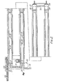
- the device shown in figs. 1 to 3 comprises a frame having horizontal frame beams 1 lying on the ground and vertical columns 2 and 3.
- the columns 2 arranged one behind the other in the direction of the length of the device and disposed on the left-hand side of the device as viewed in fig. 3 support on their sides remote from the columns 3 a plurality of superjacent rectangle-section cylinders 4 to 8 and on the sides facing the columns 3 a plurality of identical cylinders 9 to 12.
- the columns 3 support on their sides remote from the columns 2 a plurality of superjacent cylinders 13 to 17 and on their sides facing the columns 2 a plurality of superjacent cylinders 18 to 21.
- the disposition is such that the cylinders 9 to 12 located on one side of the columns 2 are off-set in a vertical direction with respect to the cylinders 4 to 8 on the other side, that is to say, by a distance substantially equal to about half the height of a cylinder.
- the cylinders 18 to 21 are off-set with respect to the cylinders 13 to 17.
- the ends of the cylinders 8 to 12 join a cabinet 22 in which is located a drum 23 to be driven about a vertical axis.
- the ends of the cylinders 13 to 21 join at one end of the device a cabinet 24 in which is arranged a drum 26 rotatable about a vertical axis and driven by a driving member 25.
- the cylinders 4 to 12 join a cabinet 27 in which a reversing drum 28 is rotatable about a vertical rotary axis.
- the cylinders 13 to 21 join a cabinet 27 also accommodating a reversing drum 30 rotatable about a vertical rotary axis.
- the two cabinets 22 and 24 communicate with one another through a cylinder 31 and the two cabinets 27 and 29 communicate with one another with the aid of a cylinder 32.
- the cabinets 22, 24, 27 and 29 are provided at appropriate places with more or less horizontal separation partitions in order to avoid undesirable contact between the superposed cylinders.
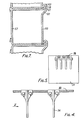
- an endless transport member which is formed in this embodiment, as is shown in figs. 4 and 5, by three endless steel cables 33 extending in superjacent positions through the cylinders and cabinets, to which blades 34 at right angles to the direction of the cables are fastened at equal intervals.
- the dimensions of the blades 34 are chosen so that they are only slightly smaller than those of the internal cross-section of the cylinders 8 to 21. In practice it has been found to be effective to leave around the blade 34 a gap of a width of about 2 mm when the blade 34 is located in the cylinder.
- the transport member formed by the cables 33 with the blades 34 fastened thereto is passed around the drums 23, 26, 28 and 29 so that starting with the cylinder 4 the transport member extends from the cabinet 22 through the cylinder 4 to the rear, is passed around the drum 28, extends through the cylinder 9 to the front, is subsequently guided around the drum 23, extends through the cylinder 5 to the rear, is guided around the drum 28 and again extends through the cylinder 10 to the front and so on. The transport member then extends through the cylinder 8 to the rear and is subsequently passed around the drum 28 and through the cylinder 32 to the drum 30.
- a transport belt 63 is arranged for the supply of the objects to be sterilized, for example, food-containing cans or pots.
- a worm conveyor 64 is arranged for displacing the supplied objects transversely of the direction of length of the conveyor belt 33 through an opening (not shown) in the sidewall of the cylinder 4 so that during operation each time one of the objects to be sterilized in the cylinder 4 is placed between two consecutive blades 34 to be carried along by the transport member formed by the cables 33 and the blades 34 across the device.
- a pick-up mechanism 35 (not shown in detail) with the aid of which the objects supplied through the cylinder 17 by means of the transport member can be delivered to a conveyor belt 36.
- a reservoir 39 has a duct 40 including a pump 41.
- the duct 40 communicates with a heat exchanger 42, to which steam from a duct 43 is supplied for heating the water emanating from the reservoir 39.
- the steam consumed in the heat exchanger is supplied through a duct 44 to the reservoir 39 for preheating the water contained therein.
- the water heated in that heat exchanger is conducted away through an outlet duct 45.
- the outlet duct 45 has branch ducts 46 to 48.
- the branch ducts include control-valves 39.
- the branch duct 46 is connected with the passage formed by the cylinders at a feeding point located at the level of the topmost cylinders 8 to 13.
- the duct 40 In front of the heat exchanger the duct 40 has connected with it a duct 50.
- the duct 50 includes a control-valve 51.
- the duct 50 communicates with the passage formed by the cylinders at the level of the transition from the cylinder 20 to the cylinder 16. At the level of the transition between the cylinders 16 and 21 the passage communicates through a connecting duct 52 with a point of the passage located at the level of the transition from the cylinder 5 to the cylinder 9.
- the reservoir 38 communicates through a duct 53 including a pump 54 with the passage at the level of the transition of the cylinder 21 to the cylinder 17.
- the duct 53 includes furthermore a controllable closing member 55.
- the supply of steam to the heat exchanger 42 from the duct 43 can be further controlled by means of a variable closing member 56.
- objects to be sterilized such as tins or pots containing foodstuff are supplied to the device through the conveyor belt 63 and be carried along by the transport member formed by the steel cables 33 and the blades 34, the objects being first progressively passed through the cylinders 4 to 12, then through the cylinder 32, subsequently through the cylinders 13 to 21 to be conducted out of the device near the end of the cylinder 17 at the cabinet 24.
- the elongate passage or the elongate hollow channel through which the objects are displaced is heated by pressurized liquid preferably water at a pressure of about 2 atms. admitted through the duct 45 and the ducts 46 to 48.
- cooling liquid can be introduced into the passage at a point located nearer the end of the passage than the feeding point(s) where the liquid heated by the heat exchanger is supplied.
- the water returning to the reservoir 38 is not preheated so that the temperature thereof will be comparatively low so that at will fairly cold water can be supplied through the duct 53 to the passage at a point located comparatively close the outlet end of the passage so that the sterilized holders will not have an excessively high temperature when leaving the device.
- the variation of the pressure and the temperature of the elongate, hollow channel through which the holders to be sterilized are continuously passed can be controlled.
- this control is automatically carried out during operation by using sensors (not shown) of pressure and/or temperature, which apply signals to the various closing members through an appropriate control-device.
- Fig. 7 shows a further suitable mode of manufacturing the cylinders.
- each cylinder is formed by a substantially hollow-section beam 57, the upper flange of the two parallel flanges being slightly longer than the lower flange and having a rim 58 bent over through an angle of about 90°.
- the open side of the hollow-section beam is closed by a plate 59, which has at its top end an outwardly bent-over part 60, which terminates in a part 61 extending parallel to the plate 58, said part connecting the bent-over part 59 with an end 62 bent over in the form of a U.
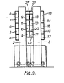
- the device shown in figs. 8 and 9 corresponds at least mainly with the device described above and corresponding parts are, therefore, designated by the same reference numerals.
- the cylinders 9 to 12 in this second embodiment are in contact with the cylinders 18 to 21 and the separating partition 65 between these cylinders has holes therein.
- the parts of the cylinders 4, 5, 16 and 17 located near the cabinets 22 and 24 respectively have outlet orifices, the outlet orifices of the cylinders 4 and 17 communicating through collecting troughs 37 with storage tanks 38, 38A and the outlet orifices of the cylinders 5 and 16 communicate with a tank 39 (fig. 10).
- pressurized liquid preferably water at a supply point located at a distance from the ends of this passage or elongate, hollow channels, said ends being formed by the ends of the cylinders 4 and 17 respectively connected with the cabinets 22 and 24 respectively.
- Fig. 10 shows a flow diagram of the liquid.
- a duct 40 including a pump 41 From a duct 43 steam can be supplied to heat the water in the reservoir 39 at a temperature of, for example, 125°C.
- the hot water is conducted away through an outlet duct 45 to the passage formed by the cylinders at a point located at the level of the topmost cylinder 8 to 13.
- water of about 45°C is displaced through the cylinder 4 and through the reservoir 38A water of about 20°C is passed in a similar manner through the cylinder 17.
- objects to be sterilized such as tins or pots containing foodstuff or similar material are supplied via the conveyor belts 63 to the device and carried along by the transport member, the objects being first progressively passed through the cylinders 4 to 12, then through the cylinders 13 to 21 and near the end of the cylinder 17 near the cabinet 24 they are conducted out of the device.
- the elongate passage i.e. the elongate, hollow channel through which the objects are displaced is heated by pressurized liquid, preferably water, at a pressure of about 2 atm., admitted through the duct 45 from a reservoir 39.
- the liquid introduced into the elongate passage will progressively flow towards the ends of the passage formed by the ends of the cylinders 5 and 16 near the cabinets 22 and 24 and from there it will flow back into the reservoir 39.
- the objects are preheated in the cylinder 4 and cooled in the cylinder 17.
- a pervious partition 65 between the adjacent cylinders 9 to 12 and 18 to 21 a satisfactory exchange of heat can take place between these cylinders.
Landscapes
- Health & Medical Sciences (AREA)
- Nutrition Science (AREA)
- Life Sciences & Earth Sciences (AREA)
- Chemical & Material Sciences (AREA)
- Engineering & Computer Science (AREA)
- Food Science & Technology (AREA)
- Polymers & Plastics (AREA)
- Food Preservation Except Freezing, Refrigeration, And Drying (AREA)
Claims (12)
Priority Applications (1)
| Application Number | Priority Date | Filing Date | Title |
|---|---|---|---|
| AT81200803T ATE10331T1 (de) | 1980-07-19 | 1981-07-13 | Vorrichtung zum sterilisieren von mit produkten gefuellten behaeltern. |
Applications Claiming Priority (4)
| Application Number | Priority Date | Filing Date | Title |
|---|---|---|---|
| NL8004172 | 1980-07-19 | ||
| NL8004172A NL8004172A (nl) | 1980-07-19 | 1980-07-19 | Werkwijze en inrichting voor het steriliseren van produkten bevattende houders. |
| NL8101368A NL8101368A (nl) | 1981-03-20 | 1981-03-20 | Inrichting voor het steriliseren van producten bevattende houders. |
| NL8101368 | 1981-03-20 |
Publications (3)
| Publication Number | Publication Date |
|---|---|
| EP0047028A2 EP0047028A2 (fr) | 1982-03-10 |
| EP0047028A3 EP0047028A3 (en) | 1982-11-24 |
| EP0047028B1 true EP0047028B1 (fr) | 1984-11-21 |
Family
ID=26645643
Family Applications (1)
| Application Number | Title | Priority Date | Filing Date |
|---|---|---|---|
| EP81200803A Expired EP0047028B1 (fr) | 1980-07-19 | 1981-07-13 | Appareil de stérilisation de récipients contenant des produits |
Country Status (9)
| Country | Link |
|---|---|
| US (1) | US4636366A (fr) |
| EP (1) | EP0047028B1 (fr) |
| AR (1) | AR229353A1 (fr) |
| AU (1) | AU553620B2 (fr) |
| BR (1) | BR8104677A (fr) |
| CA (1) | CA1180871A (fr) |
| DE (1) | DE3167303D1 (fr) |
| DK (1) | DK155570C (fr) |
| HU (1) | HU183519B (fr) |
Families Citing this family (8)
| Publication number | Priority date | Publication date | Assignee | Title |
|---|---|---|---|---|
| US5010808A (en) * | 1990-01-23 | 1991-04-30 | Apv Baker Inc. | Spiral conveyor oven |
| US4997365A (en) * | 1990-01-23 | 1991-03-05 | Apv Baker Inc. | Spiral conveyor baking apparatus |
| US5160755A (en) * | 1990-01-26 | 1992-11-03 | Campbell Soup Company | Canned product sterilizing process |
| US5277923A (en) * | 1990-01-26 | 1994-01-11 | Campbell Soup Company | Process for preparing food products |
| US5199346A (en) * | 1991-04-29 | 1993-04-06 | Fmc Corporation | Apparatus for high speed sterilization of irregularly shaped containers |
| NL9200235A (nl) * | 1992-02-07 | 1993-09-01 | Friesland Frico Domo Coop | Werkwijze en inrichting voor het aan een warmtebehandeling onderwerpen van een vloeibaar produkt. |
| US5218829A (en) * | 1992-03-10 | 1993-06-15 | Campbell Soup Company | Flexible hydrostatic cooling tower for continuous cooker |
| EP1525808A1 (fr) * | 2003-10-21 | 2005-04-27 | SIG Technology Ltd. | Pasteurisateur à tunnel |
Family Cites Families (30)
| Publication number | Priority date | Publication date | Assignee | Title |
|---|---|---|---|---|
| BE539104A (fr) * | ||||
| US1614056A (en) * | 1926-07-20 | 1927-01-11 | Ayars Machine Co | Canning machine |
| US1999430A (en) * | 1932-03-30 | 1935-04-30 | Schmidt John | Cooking apparatus |
| GB429839A (en) * | 1933-12-07 | 1935-06-07 | Food Machinery M & P Ltd | Improvements in cookers and coolers for canned goods |
| US2144334A (en) * | 1936-08-17 | 1939-01-17 | Indiana Condensed Milk Company | Apparatus for processing canned foods |
| FR824071A (fr) * | 1936-10-15 | 1938-02-01 | Procédé et appareils pour le traitement, par changement de température, de produits alimentaires ou autres contenus dans des récipients étanches et nouveaux produits améliorés obtenus | |
| GB497489A (en) * | 1937-06-24 | 1938-12-21 | Arthur Guy Enock | Improvements in apparatus for heating and cooling liquid or other foods in bottles, jars or similar vessels |
| FR952965A (fr) * | 1947-08-23 | 1949-11-28 | Perfectionnements aux appareils pour le traitement thermique de produits contenus dans des récipients clos, plus particulièrement pour la cuisson et le refroidissement de conserves alimentaires en boîtes | |
| US2660512A (en) * | 1948-02-06 | 1953-11-24 | R W Webster And Company Ltd | Method and apparatus for controlling the liquid seals on steam sterilizers |
| US2642795A (en) * | 1948-07-12 | 1953-06-23 | Bingham David William | Apparatus for heating and/or cooling canned food or other substances |
| US2789795A (en) * | 1953-01-13 | 1957-04-23 | Fmc Corp | Apparatus for treating canned goods |
| US2935930A (en) * | 1955-04-19 | 1960-05-10 | W F And John Barnes Company | Apparatus for processing foods |
| FR1272935A (fr) * | 1960-01-21 | 1961-10-06 | Appareillage de stérilisation | |
| FR78449E (fr) * | 1960-01-21 | 1962-07-20 | Appareillage de stérilisation | |
| FR1266869A (fr) * | 1960-09-05 | 1961-07-17 | Hoechst Ag | Procédé et dispositif pour sécher et stériliser en continu les flacons et objetsanalogues |
| US3101995A (en) * | 1960-09-28 | 1963-08-27 | Beauvais Max | Continuous treatment of food containers |
| FR1278910A (fr) * | 1961-01-19 | 1961-12-15 | Nagyberendezesek Export Imp Va | Installation de stérilisation fonctionnant sous surpression hydrostatique |
| FR1391729A (fr) * | 1963-10-01 | 1965-03-12 | Procédé et appareillages de traitement thermique en continu de produits placés enrécipients étanches | |
| NO122406L (fr) * | 1966-01-14 | 1900-01-01 | ||
| US3566775A (en) * | 1968-06-20 | 1971-03-02 | Int Machinery Corp Sa | Flow controlling system for cookers |
| CH502230A (de) * | 1968-08-14 | 1971-01-31 | Ursina Ag | Vorrichtung zum Sterilisieren von mit Gut, insbesondere Lebens- oder Genussmitteln, gefüllten, druckempfindliche Verschlüsse aufweisenden Packungen, sowie Verfahren zum Betrieb der Vorrichtung |
| DE2044802A1 (en) * | 1970-09-10 | 1972-03-16 | Neiss O | Water sterilizer system - sterilizing liquids or solids in sealed containers, esp food stuffs |
| CH539397A (de) * | 1971-09-28 | 1973-07-31 | Hero Conserven | Anlage zum Sterilisieren von mit Gut, insbesondere mit Lebens- oder Genussmitteln, gefüllten Packungen |
| US3774524A (en) * | 1972-02-11 | 1973-11-27 | H Howard | Apparatus for handling food products and the like |
| US3947241A (en) * | 1973-02-02 | 1976-03-30 | Heat And Control, Inc. | Food treatment apparatus and process |
| NL173913C (nl) * | 1973-07-10 | 1984-04-02 | Stork Amsterdam | Installatie voor het thermisch behandelen van in houders verpakte waren. |
| NL7315470A (nl) * | 1973-11-12 | 1975-05-14 | Stork Amsterdam | Werkwijze en inrichting voor het steriliseren of pasteuriseren van produkten verpakt in houders. |
| US4058364A (en) * | 1974-11-22 | 1977-11-15 | Q. P Corporation | High-pressure thermal sterilizer having liquid recirculating means |
| US4263254A (en) * | 1979-08-01 | 1981-04-21 | Barry-Wehmiller Company | Apparatus for and method of conserving energy in pasteurizers |
| US4279858A (en) * | 1979-11-26 | 1981-07-21 | Barry-Wehmiller Company | Energy conservation for pasteurizer apparatus |
-
1981
- 1981-07-13 EP EP81200803A patent/EP0047028B1/fr not_active Expired
- 1981-07-13 DE DE8181200803T patent/DE3167303D1/de not_active Expired
- 1981-07-17 DK DK319981A patent/DK155570C/da not_active IP Right Cessation
- 1981-07-17 AU AU73102/81A patent/AU553620B2/en not_active Ceased
- 1981-07-17 CA CA000381971A patent/CA1180871A/fr not_active Expired
- 1981-07-17 BR BR8104677A patent/BR8104677A/pt not_active IP Right Cessation
- 1981-07-17 HU HU812096A patent/HU183519B/hu not_active IP Right Cessation
- 1981-07-17 US US06/283,922 patent/US4636366A/en not_active Expired - Fee Related
- 1981-07-20 AR AR286140A patent/AR229353A1/es active
Also Published As
| Publication number | Publication date |
|---|---|
| DK319981A (da) | 1982-01-20 |
| HU183519B (en) | 1984-05-28 |
| BR8104677A (pt) | 1982-04-06 |
| EP0047028A2 (fr) | 1982-03-10 |
| EP0047028A3 (en) | 1982-11-24 |
| US4636366A (en) | 1987-01-13 |
| AR229353A1 (es) | 1983-07-29 |
| AU553620B2 (en) | 1986-07-24 |
| AU7310281A (en) | 1982-01-28 |
| DK155570B (da) | 1989-04-24 |
| DK155570C (da) | 1989-10-30 |
| CA1180871A (fr) | 1985-01-15 |
| DE3167303D1 (en) | 1985-01-03 |
Similar Documents
| Publication | Publication Date | Title |
|---|---|---|
| EP0047028B1 (fr) | Appareil de stérilisation de récipients contenant des produits | |
| US4189995A (en) | Apparatus for heating food | |
| DE68925386T2 (de) | Verfahren zum Pasteurisieren oder Sterilisieren von Nahrungsmitteln unter Verwendung von Mikrowellen und Ofen zur Ausführung eines solchen Verfahrens | |
| EP0687153B1 (fr) | Echangeur de chaleur a fluide caloporteur pour bac a friture | |
| US20100101430A1 (en) | Stackable mold unit for obtaining a molded cooked food product | |
| JPH01503205A (ja) | ダクトフィンガー付調理用オーブンおよび調理法 | |
| US3309981A (en) | Food cooker | |
| WO2000008922A1 (fr) | Procede de regulation de la temperature dans une enceinte climatisee et dispositif de climatisation | |
| EP0676028B1 (fr) | Appareil pour appliquer a des produits un traitement aux gaz | |
| EP1747729B1 (fr) | Systeme et procede de cuisson-refroidissement d'aliments par immersion sous convection forcee et diffuse | |
| US4308853A (en) | Forced hot air alimentary oven | |
| DE69112581T2 (de) | Vorrichtung zur erwärmung und abkühlung von nahrungsmittelartikeln. | |
| US5253569A (en) | Serpentine food processing with closed-loop recirculation | |
| US4531382A (en) | Spin cooler | |
| US4085668A (en) | Heat exchange apparatus for products in containers | |
| US5005272A (en) | Process in setting a web, and a heat setting plant for setting webs | |
| GB2245136A (en) | Rotary bakers' oven | |
| US2762321A (en) | Baking oven | |
| NL8200178A (nl) | Verbeterde koelruimte. | |
| JPS5829350B2 (ja) | しやく熱コ−クスを乾式冷却するための装置 | |
| US20040099154A1 (en) | Fluid distribution apparatus | |
| NL8401435A (nl) | Strijkmachine. | |
| US2209561A (en) | Cement cooler | |
| US3718981A (en) | Method and apparatus for cooling foods contained in portion containers | |
| SU602155A2 (ru) | Устройство дл дефростации пищевых продуктов |
Legal Events
| Date | Code | Title | Description |
|---|---|---|---|
| PUAI | Public reference made under article 153(3) epc to a published international application that has entered the european phase |
Free format text: ORIGINAL CODE: 0009012 |
|
| AK | Designated contracting states |
Designated state(s): AT BE CH DE FR GB IT LU NL SE |
|
| PUAL | Search report despatched |
Free format text: ORIGINAL CODE: 0009013 |
|
| AK | Designated contracting states |
Designated state(s): AT BE CH DE FR GB IT LU NL SE |
|
| 17P | Request for examination filed |
Effective date: 19830519 |
|
| ITF | It: translation for a ep patent filed | ||
| GRAA | (expected) grant |
Free format text: ORIGINAL CODE: 0009210 |
|
| AK | Designated contracting states |
Designated state(s): AT BE CH DE FR GB IT LI LU NL SE |
|
| REF | Corresponds to: |
Ref document number: 10331 Country of ref document: AT Date of ref document: 19841215 Kind code of ref document: T |
|
| REF | Corresponds to: |
Ref document number: 3167303 Country of ref document: DE Date of ref document: 19850103 |
|
| ET | Fr: translation filed | ||
| PLBE | No opposition filed within time limit |
Free format text: ORIGINAL CODE: 0009261 |
|
| STAA | Information on the status of an ep patent application or granted ep patent |
Free format text: STATUS: NO OPPOSITION FILED WITHIN TIME LIMIT |
|
| 26N | No opposition filed | ||
| ITTA | It: last paid annual fee | ||
| EPTA | Lu: last paid annual fee | ||
| EAL | Se: european patent in force in sweden |
Ref document number: 81200803.5 |
|
| PGFP | Annual fee paid to national office [announced via postgrant information from national office to epo] |
Ref country code: LU Payment date: 19960701 Year of fee payment: 16 |
|
| PGFP | Annual fee paid to national office [announced via postgrant information from national office to epo] |
Ref country code: SE Payment date: 19960705 Year of fee payment: 16 |
|
| PGFP | Annual fee paid to national office [announced via postgrant information from national office to epo] |
Ref country code: GB Payment date: 19960710 Year of fee payment: 16 |
|
| PGFP | Annual fee paid to national office [announced via postgrant information from national office to epo] |
Ref country code: CH Payment date: 19960712 Year of fee payment: 16 Ref country code: AT Payment date: 19960712 Year of fee payment: 16 |
|
| PGFP | Annual fee paid to national office [announced via postgrant information from national office to epo] |
Ref country code: NL Payment date: 19960730 Year of fee payment: 16 Ref country code: FR Payment date: 19960730 Year of fee payment: 16 |
|
| PGFP | Annual fee paid to national office [announced via postgrant information from national office to epo] |
Ref country code: BE Payment date: 19960911 Year of fee payment: 16 |
|
| PGFP | Annual fee paid to national office [announced via postgrant information from national office to epo] |
Ref country code: DE Payment date: 19960927 Year of fee payment: 16 |
|
| PG25 | Lapsed in a contracting state [announced via postgrant information from national office to epo] |
Ref country code: LU Free format text: LAPSE BECAUSE OF NON-PAYMENT OF DUE FEES Effective date: 19970713 Ref country code: GB Free format text: LAPSE BECAUSE OF NON-PAYMENT OF DUE FEES Effective date: 19970713 Ref country code: AT Free format text: LAPSE BECAUSE OF NON-PAYMENT OF DUE FEES Effective date: 19970713 |
|
| PG25 | Lapsed in a contracting state [announced via postgrant information from national office to epo] |
Ref country code: SE Effective date: 19970714 |
|
| PG25 | Lapsed in a contracting state [announced via postgrant information from national office to epo] |
Ref country code: LI Free format text: LAPSE BECAUSE OF NON-PAYMENT OF DUE FEES Effective date: 19970731 Ref country code: CH Free format text: LAPSE BECAUSE OF NON-PAYMENT OF DUE FEES Effective date: 19970731 Ref country code: BE Free format text: LAPSE BECAUSE OF NON-PAYMENT OF DUE FEES Effective date: 19970731 |
|
| BERE | Be: lapsed |
Owner name: MACHINEFABRIEK LAN B.V. Effective date: 19970731 |
|
| PG25 | Lapsed in a contracting state [announced via postgrant information from national office to epo] |
Ref country code: NL Free format text: LAPSE BECAUSE OF NON-PAYMENT OF DUE FEES Effective date: 19980201 |
|
| GBPC | Gb: european patent ceased through non-payment of renewal fee |
Effective date: 19970713 |
|
| REG | Reference to a national code |
Ref country code: CH Ref legal event code: PL |
|
| PG25 | Lapsed in a contracting state [announced via postgrant information from national office to epo] |
Ref country code: FR Free format text: LAPSE BECAUSE OF NON-PAYMENT OF DUE FEES Effective date: 19980331 |
|
| NLV4 | Nl: lapsed or anulled due to non-payment of the annual fee |
Effective date: 19980201 |
|
| PG25 | Lapsed in a contracting state [announced via postgrant information from national office to epo] |
Ref country code: DE Free format text: LAPSE BECAUSE OF NON-PAYMENT OF DUE FEES Effective date: 19980401 |
|
| EUG | Se: european patent has lapsed |
Ref document number: 81200803.5 |
|
| REG | Reference to a national code |
Ref country code: FR Ref legal event code: ST |