EP0046965A1 - Procédé et appareil pour la détermination dynamique du débit massique independant de la densité - Google Patents
Procédé et appareil pour la détermination dynamique du débit massique independant de la densité Download PDFInfo
- Publication number
- EP0046965A1 EP0046965A1 EP81106568A EP81106568A EP0046965A1 EP 0046965 A1 EP0046965 A1 EP 0046965A1 EP 81106568 A EP81106568 A EP 81106568A EP 81106568 A EP81106568 A EP 81106568A EP 0046965 A1 EP0046965 A1 EP 0046965A1
- Authority
- EP
- European Patent Office
- Prior art keywords
- flow
- fault
- disturbance
- measure
- resistance
- Prior art date
- Legal status (The legal status is an assumption and is not a legal conclusion. Google has not performed a legal analysis and makes no representation as to the accuracy of the status listed.)
- Granted
Links
Images


Classifications
-
- G—PHYSICS
- G01—MEASURING; TESTING
- G01F—MEASURING VOLUME, VOLUME FLOW, MASS FLOW OR LIQUID LEVEL; METERING BY VOLUME
- G01F1/00—Measuring the volume flow or mass flow of fluid or fluent solid material wherein the fluid passes through a meter in a continuous flow
- G01F1/05—Measuring the volume flow or mass flow of fluid or fluent solid material wherein the fluid passes through a meter in a continuous flow by using mechanical effects
- G01F1/20—Measuring the volume flow or mass flow of fluid or fluent solid material wherein the fluid passes through a meter in a continuous flow by using mechanical effects by detection of dynamic effects of the flow
- G01F1/32—Measuring the volume flow or mass flow of fluid or fluent solid material wherein the fluid passes through a meter in a continuous flow by using mechanical effects by detection of dynamic effects of the flow using swirl flowmeters
- G01F1/3209—Measuring the volume flow or mass flow of fluid or fluent solid material wherein the fluid passes through a meter in a continuous flow by using mechanical effects by detection of dynamic effects of the flow using swirl flowmeters using Karman vortices
- G01F1/3218—Measuring the volume flow or mass flow of fluid or fluent solid material wherein the fluid passes through a meter in a continuous flow by using mechanical effects by detection of dynamic effects of the flow using swirl flowmeters using Karman vortices bluff body design
-
- G—PHYSICS
- G01—MEASURING; TESTING
- G01F—MEASURING VOLUME, VOLUME FLOW, MASS FLOW OR LIQUID LEVEL; METERING BY VOLUME
- G01F1/00—Measuring the volume flow or mass flow of fluid or fluent solid material wherein the fluid passes through a meter in a continuous flow
- G01F1/05—Measuring the volume flow or mass flow of fluid or fluent solid material wherein the fluid passes through a meter in a continuous flow by using mechanical effects
- G01F1/20—Measuring the volume flow or mass flow of fluid or fluent solid material wherein the fluid passes through a meter in a continuous flow by using mechanical effects by detection of dynamic effects of the flow
- G01F1/28—Measuring the volume flow or mass flow of fluid or fluent solid material wherein the fluid passes through a meter in a continuous flow by using mechanical effects by detection of dynamic effects of the flow by drag-force, e.g. vane type or impact flowmeter
-
- G—PHYSICS
- G01—MEASURING; TESTING
- G01F—MEASURING VOLUME, VOLUME FLOW, MASS FLOW OR LIQUID LEVEL; METERING BY VOLUME
- G01F1/00—Measuring the volume flow or mass flow of fluid or fluent solid material wherein the fluid passes through a meter in a continuous flow
- G01F1/76—Devices for measuring mass flow of a fluid or a fluent solid material
- G01F1/86—Indirect mass flowmeters, e.g. measuring volume flow and density, temperature or pressure
Definitions
- the invention relates to a method for the dynamic and density-independent determination of the mass flow of fluids and devices for carrying out this method.
- the speed and dynamic pressure of the fluid are recorded at a single fault body introduced into the flow at the same time and in the same place and combined to form the result variable "mass flow”.
- the most common methods for determining the mass flow are based on measurements of the volume flow or the speed and density of the medium and the subsequent mathematical combination of these two measured variables. Dynamic real-time measurements of density are usually only possible in media where the chemical composition and the thermodynamic state functions are known. However, this is not the case for many technical applications. Even if the composition and the state functions are known, the determination of density means a high level of metrological effort, since pressure and temperature must be measured and the density calculated from this.
- the present invention is therefore based on the object of providing a simple method or a measuring device which makes it possible to dynamically determine the mass flow without knowing the density of the flow medium, i.e. also to be independent of fluctuations in chemical composition, density and speed of the fluid.
- the device should have as few moving parts as possible, should be less susceptible to contamination and should not cause excessive pressure loss at the measuring point.
- the speed v and the dynamic pressure can be measured on a single perturbation body and the mass flow m according to the relationship put together, where A denotes the flow channel cross section.
- the disturbance body used transversely to the flow serves on the one hand to generate a periodic detachment of eddies on the back.
- the relationship applies to the frequency f of these separating vortices
- Str is the Strouhal number
- v the flow velocity
- d the characteristic thickness of the disturbance body.
- the Strouhal number can be determined experimentally for each profile cross section of the fault body depending on the Reynolds number. A measurement of the vortex frequency thus immediately delivers the desired flow velocity according to equation II. In many cases, this is facilitated by the fact that the Strouhal number is constant over a wide Reynolds number range.
- the disturbance body opposes the flow with mechanical resistance.
- the force exerted by the flow on an elastically deformable or elastically supported body can be measured by the elastic deformation occurring on the body or on the bearing in accordance with a known spring characteristic.
- the drag coefficient can be for each profile cross section of the fault body can be determined experimentally depending on the Reynolds number.
- a measurement of the deformation of the fault body provides the flow force via the spring characteristic and thus the dynamic pressure sought via equation III. In many cases this is facilitated by the fact that the drag coefficient is constant over a wide Reynolds number range.
- the measurement of the fluid density is not necessary for the determination of the mass flow. Nevertheless, in addition to the speed v, which occurs directly as a result of the vortex frequency measurement, it is possible from the relationship to calculate the density j simply from the dynamic pressure (1 ⁇ 2S v 2 ) and the speed.
- the measuring method is based on the principle that a single disturbance body is introduced into the flow and that both the frequency of the detaching vortices caused by this body and the flow force acting on this body are obtained as measured variables.
- the frequency of the detaching vortices can be recorded on the disturbance body itself, since the alternating vortex shedding on both sides of the flow causes a corresponding periodic pressure drop across the body transversely to the direction of flow and excites the disturbance body to vibrate transversely to the direction of flow with the vortex frequency.
- This behavior can also be described with the help of the lift force F A on the body and a periodically variable lift coefficient c x (t) with the relationship in which (1 ⁇ 2S v 2 ) the dynamic pressure and A A the buoyancy surface of the body.
- the rotational movement can be measured especially on a rigid, rotatably mounted fault body, the rotationally changing angle of rotation being proportional to the lifting force and thus also to the product c A (t). v 2 , which corresponds to the amplitude of the measurement signal.
- the vortex shedding frequency and thus the flow velocity can be determined from the frequency of the signal.
- Vortex frequency measurement is given by attaching an ultrasonic transmitter and receiver to two opposite boundary surfaces of the flow parallel to the disturbance body in a position behind the disturbance body in the direction of flow, at which the vortexes have a particularly good design.
- the vortex modulates the acoustic signal as a density fluctuation. Odulationen the frequency of M occurring is equal to the vortex frequency.
- the flow force can be detected indirectly via the elastic deformation or deflection of the fault body or its storage in the flow direction with the aid of strain gauges, piezoresistive transducers or other displacement transducers.
- the spring characteristic of the body and the load distribution i.e. the flow profile to be known.
- the dynamic pressure or dynamic pressure can then be calculated using equation III using the drag coefficient c.
- the deflection of the fault body both in the direction of flow and perpendicular to it can also be detected in combination in a single signal.
- the total elastic deformation is due to the total force resulting from resistance and buoyancy recorded, the mean amplitude of the oscillating measurement signal of the deflection due to the flow force and the frequency of the oscillations corresponding to the vortex frequency.
- Such a combined signal detection can be technically solved, for example, by measuring the change in the electrical resistance of the current-carrying fault body or parts thereof that corresponds to the elongation of the body pers is proportional due to its deflection. Strain gauges, piezoelectric transducers or other displacement transducers attached to the body are also regarded as current-conducting parts, only one transducer measuring the entire oscillating deformation.
- the disturbance body must be dimensioned and profiled accordingly for different flow velocity ranges and fluids, so that both the vortex shedding and the body's resistance to the flow fall into particularly measurable value ranges, in which limited changes or fluctuations in the fluid properties such as density, viscosity, chemical composition and Speed, do not lead to any significant measuring errors.
- Smooth rods whose cross-sectional profile is symmetrical in the direction of flow are particularly suitable as interference bodies.
- sharp edges can be provided on the back of the profile.
- one or more surfaces parallel to the direction of flow can be attached to reinforce the oscillating pressure difference occurring due to the vortex shedding perpendicular to the direction of flow.
- the disturbing body in which the bending deformations of the disturbing body are to be used for measurement both in the direction of flow and perpendicular to it, it is also possible to optimize the bending properties of the disturbing body in that the disturbing body in two parts along its Axis is split, with each part having the most favorable area moment of inertia in each of the directions. Both parts are firmly joined at the ends and represent a single fault body. The axial distance between the two parts is determined by the maximum deflection of the front part in the direction of flow.
- the Strouhal number Str and the drag coefficient c can depend on the contraction number, i.e. on the ratio of the flow area of the fault body to the cross-sectional area of the duct, in favorable cases (e.g. with large duct diameters and slim fault bodies) an artificial one Contraction.
- This is possible in particular by inserting two guide surfaces running parallel to the direction of flow and to the fault body at a distance to be determined from the fault body.
- These guide surfaces can also be curved parallel to the channel wall, so that a coaxial inner channel is formed, in which the actual measurement is carried out, only a certain part of the total mass flow flowing through the inner channel.
- the inner channel is held on supports in the proper larger channel, wherein the supports are hollow and allow the propagation of the electrical eßsignal Oberen M.
- the extension of the guide surfaces in the direction of flow in front of and behind the fault body and the thickness of the guide surfaces must be dimensioned such that the flow in the inner channel can develop fully hydrodynamically.
- the leading edge of the guide surfaces should be well rounded.
- the method according to the invention has the advantage that the mass flow can be measured dynamically without knowing the density of the flow medium, in that only a single disturbance body is introduced into the flow.
- the cross-sectional profile of the disturbance body can be designed such that the measurement within certain limits is independent of fluctuations in the chemical composition, the density, the viscosity and the speed of the fluid.
- the process is not very susceptible to contamination of the fluid and is generally low-maintenance since there are no moving parts.
- the pressure loss at the measuring point can be kept low by appropriate design.
- the direct measurement of the flow force also takes into account the mass fraction of dirt or other phase components in the fluid in the total mass flow.
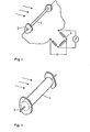
- a disturbance body If a disturbance body is brought into the flow, eddies periodically become detached. From the disturbance acting on the body flow forces, ie the resistance force F w and the periodic lifting forces F A, where F w F perpendicular to A, resulting in a deformation of an elastic body or S TOE approximately its elastic storage.
- the expression disturbance body is chosen instead of the resistance body because the body is supposed to serve for the creation of eddies in addition to the pure absorption of the resistance
- the device in Figure 1 consists of a stretch wire 1 as a fault body, which is clamped on both sides in a holder 2. By wiring into a measuring bridge 3, the wire deformation is converted into an electrical signal.
- the deformation of the disturbance body 1 is detected with a single transducer 4.
- these can be made hollow to improve the bending behavior and / or with a flexible material, e.g. Plastic, coated.
- two transducers 5 and 6 can be introduced into a hollow or solid disturbance body 1, which are oriented in such a way that one 5 the deformation by the resistance and the other 6 only the deformation by the Buoyancy forces recorded.
- the disturbance body can be designed in two parts in order to improve the bending properties with regard to the effect of resistance and buoyancy.
- the parts 7 and 8, which are perpendicular to each other, are installed th transducers 5 and 6 are attached to each other at the ends. A distance remains between the two parts to allow the front part to bend due to the resistance.
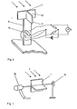
- the vortex frequency and thus the flow velocity can be measured contactlessly downstream from the disturbance body 1 by means of an ultrasonic measuring section consisting of transmitter 9 and receiver 10, as can be seen from FIG.
- the transmitter and receiver are preferably attached and adapted to the outer wall of the duct.
- a fault body 1 is supported by an elastic bearing 11, e.g. a spring element, kept in the flow.
- the disturbance body 1 has a plate 12 which is transverse to the direction of flow.
- a further plate 13 parallel to the direction of flow is provided on the rear.
- Strain gauges 14, which are attached crosswise on the front and rear of the bearing 11, serve as measuring sensors. The output signal obtained is evaluated as in the devices described above.
- a fault body 1 which has a T-shaped extension on the back. It can perform torsional vibrations about an axis that is transverse to the direction of flow. A restoring force is brought into the rest position by a torsion spring 15.
- a rotary potentiometer 16 serves as a measuring sensor. In this case, the amplitude and the frequency are evaluated from the signal obtained.
- the device shown in FIG. 8 essentially consists of a rigid disturbance body 1 with surfaces directed transversely and parallel to the direction of flow.
- two bores 17 and 18 are provided, one of which leads to the front surface and the other to a surface which is not in the dead water.
- a hot wire anemometer 22 is used for frequency measurement. The signals are evaluated in a corresponding electronics 23.
- the fault body can have different cross-sectional profiles.
- sharp edges 24 are attached to the back of the disturbance body for better detachment of the vertebrae.
- FIG. 9c A further improvement can be achieved with the embodiment shown in FIG. 9c, in which a surface 25 running parallel to the direction of flow and additionally at the end of this surface for better shaping of the vortices are attached to the rear of the fault body.
- Figure 9 may be present d obliquely to dirt particles or similar particles contained in the fluid dismissed at the front of body disturbance to the flow direction inclined surfaces 27 shown.
- the front of the fault body is well rounded off for the same purpose.
- the cross section of the flow channel can be changed to adapt the disturbance body to the flow conditions.
- this is achieved by attaching two flat, thin-walled guide surfaces 28, optionally held by supports, parallel to the flow and parallel and at the same distance from the disturbance body 1.
- the inlet edges should be well rounded and the lengths of the surfaces 28 in front of and behind the interference body 1 should be dimensioned such that the flow in the inner measuring channel formed through which only a partial mass flow of the fluid flows is hydrodynamic.
- the same effect is achieved by attaching a coaxial measuring channel 29 in the flow channel, only a partial mass flow of the fluid flowing through this measuring channel and the fault body 1 being used only in this measuring channel.
- the measuring channel wall should be thin and well rounded at the inlet.
- the length of the measuring channel should ensure a hydrodynamically designed flow in front of and behind the interference body.
- the measuring channel is held by supports 30 which are hollow and thus enable the electrical signal lines to be passed on from or to the measuring transducers through the measuring channel wall and through the outer channel wall.
Landscapes
- Physics & Mathematics (AREA)
- Fluid Mechanics (AREA)
- General Physics & Mathematics (AREA)
- Measuring Volume Flow (AREA)
- Complex Calculations (AREA)
Priority Applications (1)
| Application Number | Priority Date | Filing Date | Title |
|---|---|---|---|
| AT81106568T ATE17606T1 (de) | 1980-08-29 | 1981-08-25 | Verfahren und vorrichtung zur dynamischen und dichteunabhaengigen bestimmung des massenstroms. |
Applications Claiming Priority (2)
| Application Number | Priority Date | Filing Date | Title |
|---|---|---|---|
| DE3032578A DE3032578C2 (de) | 1980-08-29 | 1980-08-29 | Verfahren und Vorrichtung zur dynamischen und dichteunabhängigen Bestimmung des Massenstroms |
| DE3032578 | 1980-08-29 |
Publications (2)
| Publication Number | Publication Date |
|---|---|
| EP0046965A1 true EP0046965A1 (fr) | 1982-03-10 |
| EP0046965B1 EP0046965B1 (fr) | 1986-01-22 |
Family
ID=6110679
Family Applications (1)
| Application Number | Title | Priority Date | Filing Date |
|---|---|---|---|
| EP81106568A Expired EP0046965B1 (fr) | 1980-08-29 | 1981-08-25 | Procédé et appareil pour la détermination dynamique du débit massique independant de la densité |
Country Status (4)
| Country | Link |
|---|---|
| US (1) | US4448081A (fr) |
| EP (1) | EP0046965B1 (fr) |
| AT (1) | ATE17606T1 (fr) |
| DE (2) | DE3032578C2 (fr) |
Cited By (5)
| Publication number | Priority date | Publication date | Assignee | Title |
|---|---|---|---|---|
| WO1985000883A1 (fr) * | 1983-08-04 | 1985-02-28 | The Foxboro Company | Debitmetre de masse a partage tourbillonnaire pour mesures dans un plan |
| DE19740707A1 (de) * | 1997-09-16 | 1999-03-25 | Kem Kueppers Elektromech Gmbh | Meßwertgeber für Wirbeldurchflußmesser |
| DE19740708A1 (de) * | 1997-09-16 | 1999-03-25 | Kem Kueppers Elektromech Gmbh | Meßwertgeber für Wirbeldurchflußmesser |
| DE10227726A1 (de) * | 2002-06-21 | 2004-01-15 | Invensys Metering Systems Ag | Wirbeldurchflussmesser |
| WO2006122694A2 (fr) * | 2005-05-19 | 2006-11-23 | Technische Universität Darmstadt | Procede pour surveiller une mesure de debit de fluide et systeme de capteur pour une mesure de debit de fluide |
Families Citing this family (35)
| Publication number | Priority date | Publication date | Assignee | Title |
|---|---|---|---|---|
| EP0110321B1 (fr) * | 1982-11-25 | 1988-09-07 | Oval Engineering Co., Ltd. | Débitmètre à vortex |
| JPS6162820A (ja) * | 1984-09-04 | 1986-03-31 | Toyota Motor Corp | カルマン渦エアフロ−センサを用いた吸入空気質量流量検出装置 |
| DE3775507D1 (de) * | 1986-09-30 | 1992-02-06 | Siemens Ag | Stroemungsmengenmesser nach dem wirbel-durchflussmesser-prinzip, insbesondere luftmengenmesser fuer elektrische einspritzsteuerungen bei kfz-motoren. |
| US4779458A (en) * | 1986-12-29 | 1988-10-25 | Mawardi Osman K | Flow sensor |
| US4864868A (en) * | 1987-12-04 | 1989-09-12 | Schlumberger Industries, Inc. | Vortex flowmeter transducer |
| DE3800219A1 (de) * | 1988-01-07 | 1989-07-20 | Helmut Dipl Ing Roppelt | Verfahren und messvorrichtung zur volumenbestimmung von abgasstroemen, insbesondere zur autoabgas-volumenbestimmung |
| DE3916056A1 (de) * | 1989-05-17 | 1990-11-22 | Kuipers Ulrich | Messverfahren und vorrichtung zur massendurchfluss-, volumendurchfluss-, dichte- und/oder viskositaetsbestimmung und daraus abgeleiteten groessen |
| US5152181A (en) * | 1990-01-19 | 1992-10-06 | Lew Hyok S | Mass-volume vortex flowmeter |
| US5060522A (en) * | 1990-01-19 | 1991-10-29 | Lew Hyok S | Mass-volume vortex flowmeter |
| US5372046A (en) * | 1992-09-30 | 1994-12-13 | Rosemount Inc. | Vortex flowmeter electronics |
| US5351559A (en) * | 1993-08-31 | 1994-10-04 | National Science Council | T-shape vortex shedder wherein the bluff body extends across the diameter of a circular pipe and has a length to width ratio between 1.56 and 2.0 |
| US5463904A (en) * | 1994-02-04 | 1995-11-07 | The Foxboro Company | Multimeasurement vortex sensor for a vortex-generating plate |
| US5447073A (en) * | 1994-02-04 | 1995-09-05 | The Foxboro Company | Multimeasurement replaceable vortex sensor |
| DE19619632A1 (de) * | 1996-05-15 | 1997-11-20 | S K I Schlegel & Kremer Indust | Verfahren und Einrichtung zur Messung der Dichte und/oder des Massenstromes eines strömenden Fluids |
| US5880377A (en) * | 1996-10-15 | 1999-03-09 | Lsi Logic Corporation | Method for low velocity measurement of fluid flow |
| US5804740A (en) * | 1997-01-17 | 1998-09-08 | The Foxboro Company | Capacitive vortex mass flow sensor |
| US6170338B1 (en) | 1997-03-27 | 2001-01-09 | Rosemont Inc. | Vortex flowmeter with signal processing |
| US6267013B1 (en) | 1998-11-18 | 2001-07-31 | Stephen T. Stark | Flow anomaly detector |
| US6865957B1 (en) * | 2002-04-17 | 2005-03-15 | Nathaniel Hughes | Adaptable fluid mass flow meter device |
| DE10240189A1 (de) * | 2002-08-28 | 2004-03-04 | Endress + Hauser Flowtec Ag, Reinach | Verfahren zum Ermitteln eines Massendurchflusses eines in einer Rohrleitung strömenden Fluids |
| US7212928B2 (en) * | 2002-09-06 | 2007-05-01 | Invensys Systems, Inc. | Multi-measurement vortex flow meter |
| RU2339008C2 (ru) | 2004-03-25 | 2008-11-20 | Роузмаунт Инк. | Упрощенное измерение свойства текучей среды |
| EP1936332A1 (fr) * | 2006-12-22 | 2008-06-25 | Nederlandse Organisatie voor Toegepast-Natuuurwetenschappelijk Onderzoek TNO | Débitmètre utilisant des vortices de Karman comprenant un capteur à fibre optique à réseau de Bragg ainsi qu'un procédé de mesure d'un débit d'un fluide |
| US10423172B2 (en) * | 2008-03-07 | 2019-09-24 | Belimo Holding Ag | Device for measuring and regulating a volume flow in a ventilation pipe |
| US9250108B2 (en) * | 2013-09-27 | 2016-02-02 | Rosemount Inc. | Differential pressure based flow measurement device having improved pitot tube configuration |
| DE102013019872B4 (de) * | 2013-11-28 | 2023-03-30 | Universität des Saarlandes Campus Saarbrücken | Verfahren und Vorrichtung zur Bestimmung der Viskosität einer in einem Strömungskanal strömenden Flüssigkeit |
| DE102015000629A1 (de) * | 2015-01-22 | 2016-07-28 | Viessmann Werke Gmbh & Co Kg | Turboverdichter |
| CN108601558B (zh) * | 2015-12-28 | 2020-12-18 | 普林斯顿大学 | 弹性丝速度传感器 |
| EP3546954B1 (fr) * | 2016-01-07 | 2022-12-14 | Analog Devices, Inc. | Accéléromètre angulaire triaxial |
| RU2705705C1 (ru) * | 2016-07-21 | 2019-11-11 | Майкро Моушн, Инк. | Вихревой расходомер с уменьшенным технологическим вмешательством |
| CN110199178B (zh) | 2016-12-06 | 2021-01-01 | Ysi公司 | 用于补偿动水中的压力传感器上的文丘里效应的方法 |
| EP3576812A4 (fr) * | 2017-02-23 | 2020-08-05 | The Trustees of Princeton University | Système et procédé destinés à contrôler la pression au site d'injection |
| RU2765608C1 (ru) * | 2018-08-30 | 2022-02-01 | Майкро Моушн, Инк. | Неинвазивный датчик для вихревого расходомера |
| WO2020139097A1 (fr) | 2018-12-24 | 2020-07-02 | Micro Motion, Inc. | Débitmètre à tourbillon à deux capteurs |
| CN110206688B (zh) * | 2019-06-13 | 2020-09-29 | 石家庄铁道大学 | 发电装置 |
Citations (6)
| Publication number | Priority date | Publication date | Assignee | Title |
|---|---|---|---|---|
| US3719073A (en) * | 1970-09-14 | 1973-03-06 | American Standard Inc | Mass flow meter |
| FR2173962A1 (fr) * | 1972-01-17 | 1973-10-12 | Omf California Inc | |
| US3878716A (en) * | 1973-12-19 | 1975-04-22 | Hokushin Electric Works | Karman vortex shedder |
| US3996796A (en) * | 1975-03-10 | 1976-12-14 | Corning Glass Works | Flow meter |
| US4112879A (en) * | 1975-02-24 | 1978-09-12 | Robert Bosch Gmbh | Process for the regulation of the optimum operational behavior of an internal combustion engine |
| US4196621A (en) * | 1975-11-20 | 1980-04-08 | National Research Development Corporation | Devices for detecting fluid flow |
Family Cites Families (16)
| Publication number | Priority date | Publication date | Assignee | Title |
|---|---|---|---|---|
| BE394587A (fr) * | 1932-02-25 | |||
| US3370463A (en) * | 1964-07-29 | 1968-02-27 | American Standard Inc | Mass flow meter |
| US3587312A (en) * | 1968-12-24 | 1971-06-28 | Eastech | Differential sensor bluff body flowmeter |
| US3927566A (en) * | 1971-06-17 | 1975-12-23 | Kent Instruments Ltd | Flowmeters |
| US3885432A (en) * | 1972-03-06 | 1975-05-27 | Fischer & Porter Co | Vortex-type mass flowmeters |
| US3888120A (en) * | 1973-04-26 | 1975-06-10 | Fischer & Porter Co | Vortex type flowmeter with strain gauge sensor |
| US3863501A (en) * | 1973-12-19 | 1975-02-04 | Honeywell Inc | Magnetostrictive sensor for a flowmeter |
| DE2408246C3 (de) * | 1974-02-21 | 1981-10-15 | Bopp & Reuther Gmbh, 6800 Mannheim | Durchflußmeßgerät |
| US3972232A (en) * | 1974-04-24 | 1976-08-03 | The Foxboro Company | Vortex flow meter apparatus |
| US4010645A (en) * | 1976-03-19 | 1977-03-08 | Fischer & Porter Co. | Density-responsive mass flow vortex type meter |
| SE7713507L (sv) * | 1976-12-02 | 1978-06-03 | Garrett Corp | Sett och anordning for bestemning av ett massaflode |
| US4171643A (en) * | 1976-12-29 | 1979-10-23 | Rosemount Inc. | Vortex shedding flowmeter construction |
| DE2827985C2 (de) * | 1977-11-10 | 1984-03-08 | Yokogawa Hokushin Electric Corp., Musashino, Tokyo | Strömungsmesser |
| US4281553A (en) * | 1978-05-04 | 1981-08-04 | Datta Barua Lohit | Vortex shedding flowmeter |
| JPS5576916A (en) * | 1978-12-06 | 1980-06-10 | Nissan Motor Co Ltd | Sucked air quantity detector |
| JPS5582018A (en) * | 1978-12-15 | 1980-06-20 | Nissan Motor Co Ltd | Karman vortex flowmeter |
-
1980
- 1980-08-29 DE DE3032578A patent/DE3032578C2/de not_active Expired
-
1981
- 1981-08-21 US US06/295,021 patent/US4448081A/en not_active Expired - Fee Related
- 1981-08-25 DE DE8181106568T patent/DE3173562D1/de not_active Expired
- 1981-08-25 EP EP81106568A patent/EP0046965B1/fr not_active Expired
- 1981-08-25 AT AT81106568T patent/ATE17606T1/de not_active IP Right Cessation
Patent Citations (6)
| Publication number | Priority date | Publication date | Assignee | Title |
|---|---|---|---|---|
| US3719073A (en) * | 1970-09-14 | 1973-03-06 | American Standard Inc | Mass flow meter |
| FR2173962A1 (fr) * | 1972-01-17 | 1973-10-12 | Omf California Inc | |
| US3878716A (en) * | 1973-12-19 | 1975-04-22 | Hokushin Electric Works | Karman vortex shedder |
| US4112879A (en) * | 1975-02-24 | 1978-09-12 | Robert Bosch Gmbh | Process for the regulation of the optimum operational behavior of an internal combustion engine |
| US3996796A (en) * | 1975-03-10 | 1976-12-14 | Corning Glass Works | Flow meter |
| US4196621A (en) * | 1975-11-20 | 1980-04-08 | National Research Development Corporation | Devices for detecting fluid flow |
Cited By (8)
| Publication number | Priority date | Publication date | Assignee | Title |
|---|---|---|---|---|
| WO1985000883A1 (fr) * | 1983-08-04 | 1985-02-28 | The Foxboro Company | Debitmetre de masse a partage tourbillonnaire pour mesures dans un plan |
| DE19740707A1 (de) * | 1997-09-16 | 1999-03-25 | Kem Kueppers Elektromech Gmbh | Meßwertgeber für Wirbeldurchflußmesser |
| DE19740708A1 (de) * | 1997-09-16 | 1999-03-25 | Kem Kueppers Elektromech Gmbh | Meßwertgeber für Wirbeldurchflußmesser |
| DE19740707C2 (de) * | 1997-09-16 | 1999-12-02 | Kem Kueppers Elektromech Gmbh | Meßwertgeber für Wirbeldurchflußmesser |
| DE19740708C2 (de) * | 1997-09-16 | 1999-12-09 | Kem Kueppers Elektromech Gmbh | Meßwertgeber für Wirbeldurchflußmesser |
| DE10227726A1 (de) * | 2002-06-21 | 2004-01-15 | Invensys Metering Systems Ag | Wirbeldurchflussmesser |
| WO2006122694A2 (fr) * | 2005-05-19 | 2006-11-23 | Technische Universität Darmstadt | Procede pour surveiller une mesure de debit de fluide et systeme de capteur pour une mesure de debit de fluide |
| WO2006122694A3 (fr) * | 2005-05-19 | 2007-02-15 | Univ Darmstadt Tech | Procede pour surveiller une mesure de debit de fluide et systeme de capteur pour une mesure de debit de fluide |
Also Published As
| Publication number | Publication date |
|---|---|
| DE3032578A1 (de) | 1982-03-18 |
| ATE17606T1 (de) | 1986-02-15 |
| US4448081A (en) | 1984-05-15 |
| EP0046965B1 (fr) | 1986-01-22 |
| DE3032578C2 (de) | 1983-11-03 |
| DE3173562D1 (en) | 1986-03-06 |
Similar Documents
| Publication | Publication Date | Title |
|---|---|---|
| EP0046965B1 (fr) | Procédé et appareil pour la détermination dynamique du débit massique independant de la densité | |
| DE2640087C2 (fr) | ||
| EP2406585B1 (fr) | Procédé et appareil de mesure d'écoulement tourbillonnaire, destinés à surveiller et/ou mesurer un écoulement pariétal d'un fluide traversant une conduite tubulaire et possédant deux phases ou plus | |
| DE69008257T2 (de) | Wirbeldurchflussmesser. | |
| DE69411793T2 (de) | Wirbeldurchflussmesser mit zweiflügeligem Strouhalnummernkorrektor | |
| DE2512644A1 (de) | Vorrichtung zur messung des durchflusses und/oder viskositaet von fluiden | |
| DE102004053673A1 (de) | Vorrichtung zur Bestimmung und/oder Überwachung des Volumen- und/oder Massendurchflusses eines Mediums | |
| DE2204269B2 (de) | Länglicher Wirbelkörper zum Messen der Strömungsgeschwindigkeit eines Strömungsmittels in einer Leitung | |
| DE102015105685B3 (de) | Verfahren und Vorrichtung zum Erkennen des Vorhandenseins von Flüssigkeit in einem Gasstrom | |
| EP3325923B1 (fr) | Débitmètre selon le principe de comptage de tourbillons | |
| DE102008013224A1 (de) | Messsystem und Verfahren zur Bestimmung und/oder Überwachung eines Durchflusses eines Messmediums durch ein Messrohr | |
| WO2014191136A1 (fr) | Dispositif pour déterminer et/ou surveiller le débit volumique et/ou massique d'un fluide | |
| EP1556670B1 (fr) | Debitmetre a tourbillons | |
| DE3036186A1 (de) | Stabilisierter wirbelabloesender stroemungsmesser | |
| DE102008055032B4 (de) | Anordnung und Verfahren zur Mehrphasendurchflussmessung | |
| DE2900385A1 (de) | Stroemungsmessgeraet | |
| DE69506852T2 (de) | Wirbelströmungsmessgerät mit einem profilierten messrohr | |
| DE2652002A1 (de) | Stroemungsmesser | |
| EP3748308A1 (fr) | Débitmètre à ultrasons, utilisation d'un débitmètre à ultrasons dans un organe d'arrêt et organe d'arrêt | |
| DE2757298A1 (de) | Stroemungsmessgeraet | |
| EP0682772A1 (fr) | Sonde rheometrique | |
| DE3919299A1 (de) | Wellmembran | |
| EP0431345B1 (fr) | Capteur pour la mesure de pression d'un fluide passant dans un tuyau | |
| DE2802830B2 (de) | Fluidströmungsmesser | |
| EP0207321B1 (fr) | Dispositif pour la mesure du débit |
Legal Events
| Date | Code | Title | Description |
|---|---|---|---|
| PUAI | Public reference made under article 153(3) epc to a published international application that has entered the european phase |
Free format text: ORIGINAL CODE: 0009012 |
|
| AK | Designated contracting states |
Designated state(s): AT BE CH DE FR GB IT LI LU NL SE |
|
| 17P | Request for examination filed |
Effective date: 19820608 |
|
| GRAA | (expected) grant |
Free format text: ORIGINAL CODE: 0009210 |
|
| STAA | Information on the status of an ep patent application or granted ep patent |
Free format text: STATUS: THE PATENT HAS BEEN GRANTED |
|
| AK | Designated contracting states |
Designated state(s): AT BE CH DE FR GB IT LI LU NL SE |
|
| PG25 | Lapsed in a contracting state [announced via postgrant information from national office to epo] |
Ref country code: NL Effective date: 19860122 Ref country code: IT Free format text: LAPSE BECAUSE OF FAILURE TO SUBMIT A TRANSLATION OF THE DESCRIPTION OR TO PAY THE FEE WITHIN THE PRESCRIBED TIME-LIMIT;WARNING: LAPSES OF ITALIAN PATENTS WITH EFFECTIVE DATE BEFORE 2007 MAY HAVE OCCURRED AT ANY TIME BEFORE 2007. THE CORRECT EFFECTIVE DATE MAY BE DIFFERENT FROM THE ONE RECORDED. Effective date: 19860122 Ref country code: FR Free format text: THE PATENT HAS BEEN ANNULLED BY A DECISION OF A NATIONAL AUTHORITY Effective date: 19860122 Ref country code: BE Effective date: 19860122 |
|
| REF | Corresponds to: |
Ref document number: 17606 Country of ref document: AT Date of ref document: 19860215 Kind code of ref document: T |
|
| PG25 | Lapsed in a contracting state [announced via postgrant information from national office to epo] |
Ref country code: SE Effective date: 19860131 |
|
| REF | Corresponds to: |
Ref document number: 3173562 Country of ref document: DE Date of ref document: 19860306 |
|
| EN | Fr: translation not filed | ||
| NLV1 | Nl: lapsed or annulled due to failure to fulfill the requirements of art. 29p and 29m of the patents act | ||
| PG25 | Lapsed in a contracting state [announced via postgrant information from national office to epo] |
Ref country code: AT Effective date: 19860825 |
|
| PG25 | Lapsed in a contracting state [announced via postgrant information from national office to epo] |
Ref country code: LU Free format text: LAPSE BECAUSE OF NON-PAYMENT OF DUE FEES Effective date: 19860831 Ref country code: LI Effective date: 19860831 Ref country code: CH Effective date: 19860831 |
|
| PLBE | No opposition filed within time limit |
Free format text: ORIGINAL CODE: 0009261 |
|
| 26N | No opposition filed | ||
| GBPC | Gb: european patent ceased through non-payment of renewal fee | ||
| REG | Reference to a national code |
Ref country code: CH Ref legal event code: PL |
|
| PG25 | Lapsed in a contracting state [announced via postgrant information from national office to epo] |
Ref country code: DE Effective date: 19880503 |
|
| PG25 | Lapsed in a contracting state [announced via postgrant information from national office to epo] |
Ref country code: GB Effective date: 19881118 |