EP0046705B1 - Verbindung zwischen einer Kunststoffleitung und einer metallischen Leitung für eine Flüssigkeit unter Druck - Google Patents
Verbindung zwischen einer Kunststoffleitung und einer metallischen Leitung für eine Flüssigkeit unter Druck Download PDFInfo
- Publication number
- EP0046705B1 EP0046705B1 EP19810401285 EP81401285A EP0046705B1 EP 0046705 B1 EP0046705 B1 EP 0046705B1 EP 19810401285 EP19810401285 EP 19810401285 EP 81401285 A EP81401285 A EP 81401285A EP 0046705 B1 EP0046705 B1 EP 0046705B1
- Authority
- EP
- European Patent Office
- Prior art keywords
- pipe
- clamping
- sleeve
- sheath
- joint
- Prior art date
- Legal status (The legal status is an assumption and is not a legal conclusion. Google has not performed a legal analysis and makes no representation as to the accuracy of the status listed.)
- Expired
Links
- 229920003023 plastic Polymers 0.000 title claims description 38
- 239000004033 plastic Substances 0.000 title claims description 38
- 239000002184 metal Substances 0.000 title claims description 10
- 239000012530 fluid Substances 0.000 title claims description 3
- 238000007789 sealing Methods 0.000 claims description 13
- 239000004698 Polyethylene Substances 0.000 claims description 2
- -1 polyethylene Polymers 0.000 claims description 2
- 229920000573 polyethylene Polymers 0.000 claims description 2
- 230000013011 mating Effects 0.000 claims 1
- 239000000463 material Substances 0.000 description 8
- 229910000831 Steel Inorganic materials 0.000 description 5
- 239000010959 steel Substances 0.000 description 5
- 229920001903 high density polyethylene Polymers 0.000 description 2
- 239000004700 high-density polyethylene Substances 0.000 description 2
- 238000009434 installation Methods 0.000 description 2
- 230000035515 penetration Effects 0.000 description 2
- 229920000915 polyvinyl chloride Polymers 0.000 description 2
- 239000004800 polyvinyl chloride Substances 0.000 description 2
- 230000000717 retained effect Effects 0.000 description 2
- 230000032683 aging Effects 0.000 description 1
- 230000000903 blocking effect Effects 0.000 description 1
- 230000006835 compression Effects 0.000 description 1
- 238000007906 compression Methods 0.000 description 1
- 230000001268 conjugating effect Effects 0.000 description 1
- 239000000470 constituent Substances 0.000 description 1
- 230000006378 damage Effects 0.000 description 1
- 230000006837 decompression Effects 0.000 description 1
- 230000001419 dependent effect Effects 0.000 description 1
- 230000001627 detrimental effect Effects 0.000 description 1
- 238000006073 displacement reaction Methods 0.000 description 1
- 230000000694 effects Effects 0.000 description 1
- 238000000605 extraction Methods 0.000 description 1
- 230000007774 longterm Effects 0.000 description 1
- 230000001737 promoting effect Effects 0.000 description 1
- XLYOFNOQVPJJNP-UHFFFAOYSA-N water Substances O XLYOFNOQVPJJNP-UHFFFAOYSA-N 0.000 description 1
- 238000003466 welding Methods 0.000 description 1
Images
Classifications
-
- F—MECHANICAL ENGINEERING; LIGHTING; HEATING; WEAPONS; BLASTING
- F16—ENGINEERING ELEMENTS AND UNITS; GENERAL MEASURES FOR PRODUCING AND MAINTAINING EFFECTIVE FUNCTIONING OF MACHINES OR INSTALLATIONS; THERMAL INSULATION IN GENERAL
- F16L—PIPES; JOINTS OR FITTINGS FOR PIPES; SUPPORTS FOR PIPES, CABLES OR PROTECTIVE TUBING; MEANS FOR THERMAL INSULATION IN GENERAL
- F16L47/00—Connecting arrangements or other fittings specially adapted to be made of plastics or to be used with pipes made of plastics
- F16L47/005—Connecting arrangements or other fittings specially adapted to be made of plastics or to be used with pipes made of plastics the first pipe being joined to the ends of two other pipes placed one inside the other, e.g. gas pipe with protective sheath
Definitions
- the present invention relates to a connector for connecting a plastic pipe for pressurized fluid and a metal pipe, fitting used, for example, for a front crossing of a gas subscriber.
- the plastic pipe is then subjected to natural or accidental movements of the ground, the roadway or the sidewalks and may even, during certain road works carried out using extraction machines, undergo accidental traction forces tending to tear off the plastic pipe from the fitting that connects it to the metal pipe located at the gas customer's home.
- the connector according to the invention has the advantage, on the one hand, of being self-tightening under the effect of the tensile forces applied to the plastic pipe, on the other hand, of having its clamping system functionally independent of its sealing system.
- the connector described in French patent FR-A-2 260 056 comprises substantially identical constituent elements. However, they are arranged differently since the sealing and tightening functions are intimately linked. Indeed, the O-ring which ensures one of the seals of this connection, is arranged in such a way that one cannot control its degree of compression, both during the fitting of the fitting and during the time. In addition, it results from a traction exerted on this fitting a decompression of this seal and consequently an obvious risk of leakage at this level. The seal on the other side is ensured by the penetration of the teeth of the ring into the plastic material of the pipe. Due to the creep inherent in the plastic material and the long-term adoption of the forms by this material, the sealing at this level does not have an acceptable service life for a durable connection.
- the plastic pipe undergoes an initial traction when the fitting is put in place, therefore a stretching which, combined with the obligation of initial penetration of the teeth in the plastic material is detrimental to the safety required in the field.
- the purpose of the fitting according to the invention is to obviate these drawbacks by completely separating the tightening and sealing functions, so that the latter is ensured both over time (aging of the seals) and in the event of an accident (traction exerted on the connector), thus promoting user safety.
- this material is not deeply injured during the fitting of the fitting.
- the teeth of the clamping cone really penetrate into the plastic material only in the event of traction exerted on the pipe. The plastic pipe is therefore, in practice, not subjected to efforts or to significant injuries at the time of installation.
- the connector according to the invention is characterized in that the clamping sleeve is fixed permanently, the second end of the housing being screwed onto the fixed clamping sleeve during the fitting of the connector until that the inner shoulder of the housing comes into abutment on the collar of the ferrule, and in that the sealing of the fitting is ensured on the one hand, by a first sealing O-ring housed in an annular groove made in the wall inside of the middle part of the housing, this first seal contacting the fixed clamping sleeve, and on the other hand, by a second O-ring seal housed in an annular groove made in the inner wall of the second end of the clamping sleeve, this second seal contacting the plastic pipe, so as to separate the clamping and sealing functions.
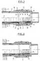
- FIG. 1 the pipe made of plastic, for example polyvinyl chloride or better still high density polyethylene is shown at 1 at the exit of its passage through a wall 2.
- the connector according to the invention consists of the various steel parts described below and having an axial symmetry with respect to the axis 3 of the pipe 1.
- the metal pipe to which the connector is fixed by its outer casing 4 has not been shown in the drawing. It is for example screwed to the end of the housing 4 to the right of FIG. 1.
- the first part to be put in place during assembly of the fitting is a clamping sleeve 5 around the part of the plastic pipe 1 arriving at the gas subscriber after crossing the wall 2.
- a steel sleeve 6 is generally engaged beforehand around the end of the pipe 1 to be subsequently sealed in the wall 2 after having been coated with an insulating layer 7 of polyethylene.
- the clamping sheath 5 put in place after the sleeve 6 around the pipe 1 can be fixed to the latter for example by welding.
- the wall side end 2 of the clamping sleeve 5 has a cylindrical inner face 8 which can slide with gentle friction around the pipe 1 and an outer face provided with two clamping flats 9 and a threaded part 10.
- the other end is cylindrical on the outside and has a conical bore 11.
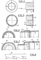
- Two half views of the sleeve 5 are given in FIG. 6 where the same references are found as those used in FIG. 1.
- the second part to be put in place during assembly of the fitting is a clamping cone 12 partially engaging through its apex in the conical gap between the sheath 5 and the pipe 1.
- This cone 12 has, in fact, a conical outer face which combines with the conical bore 11 of the sleeve and a flat base 13.
- Two views are given in FIG. 5. It is a cone made up of several sectors, three for example in FIG. 5, separated by a set of compensators and retained by a steel rod 14 disposed in an outer groove at its base.
- the conical faces of the cone 12 and of the clamping sleeve 5 have a taper of 15 to 20%.
- the inner face of the cone 12 is provided with an annular toothing 15 with a sawtooth profile which is in contact by the top of its teeth with the outer wall of the pipe 1.
- the edges of the teeth are preferably truncated so as to make them non-cutting for the plastic of the pipe 1.
- the truncation of the teeth forms a flat of revolution of about 0.3 mm like that indicated at 20 in FIG. 8.
- the end of the pipe 1 is then sectioned so that it comes flush with the base 13 of the clamping cone 12 after the cone has been placed by hand between the sheath 5 and the pipe 1.
- the third part to be put in place during assembly of the fitting is a ferrule 16, a drawing in two views is given in FIG. 4.
- This ferrule 16 is a part of revolution along the axis 3 which is introduced inside from the end of the pipe 1 against the edge of which it abuts by its flange 17 which is also in abutment on the flat face of the base 13 of the clamping cone.
- the body of the ferrule 16, which is internally cylindrical, is provided on its outer face with an annular toothing 18 in contact by the top of its teeth with the internal wall of the end of the pipe 1.
- the sawtooth profile of this toothing 18 is shown on a larger scale in Figure 8. It is the same profile as that of the inner face of the clamping cone 12.
- the fronts 19 of all the teeth are turned towards the flange 17 as well for the cone 12 as for the ferrule 16, but the teeth of the latter are offset on either side of the plastic pipe so as not to be opposite.
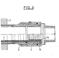
- the aim of the sawtooth profile with respect to the pipe 1 is to hook the end of this pipe inside the connector to oppose accidental traction forces on the pipe 1 because, once the fitting is installed, tightening it makes the teeth penetrate the thickness of this pipe.
- FIG. 8 shows the truncation 20 of the teeth of the ferrule 16 identical to that of the teeth of the cone 12.
- the fourth part to be put in place during assembly of the fitting is the housing 4 surrounding all of the preceding parts and comprising at its end 21, on the wall side 2, a thread 22 allowing it to be screwed onto the threaded part 10 sheath 5 using a key, for example a torque wrench.
- a key for example a torque wrench.
- two flats 23 are arranged a few centimeters from the other end of the housing 4.
- the middle part of the housing 4 slides with gentle friction on the cylindrical external face of the sleeve 5.
- the other end of the housing 4, side opposite to the wall 2, that is to say on the side of the pipe metal, is provided with an inner shoulder 24 abutting on the flange 17 of the shell during screwing, which then causes, as soon as this shoulder 24 has come into abutment, on the flange 17, the relative advancement of the sheath 5 towards the end of the plastic pipe and a slight depression of the teeth of the clamping cone and the ferrule in the thickness of this pipe.
- FIG. 7 represents two half-views of the housing 4.
- two O-rings 25 and 26 are housed in annular grooves made respectively in the interior wall from the middle part of the housing 4 for the first seal 25 and in the inner wall of the end of the clamping sleeve situated on the wall side 2 for the second seal 26. It can be seen that the sealing system is independent of the clamping system.
- a blocking device for example, as can be seen in FIGS. 1, 2, 3 and 7, by means of a steel needle screw 27 with hexagon socket, disposed through the wall of the middle part of the housing 4 and tightened for example against the sheath 5 using a hexagonal male key.
- FIG. 1 shows the fitting assembled by hand and ready to be tightened
- FIG. 2 shows the position of the different parts of the fitting after the controlled tightening carried out with a torque wrench by the fitter before putting the pipe into service
- FIG. 3 shows the relative displacements undergone by the parts of the fitting after the plastic pipe has been subjected to a significant traction caused for example by a backhoe during road works.
Landscapes
- Engineering & Computer Science (AREA)
- General Engineering & Computer Science (AREA)
- Mechanical Engineering (AREA)
- Joints With Pressure Members (AREA)
- Joints With Sleeves (AREA)
- Laying Of Electric Cables Or Lines Outside (AREA)
Claims (5)
wobei die Verbindung dadurch gekennzeichnet ist, dass das genannte Spannfutter (5) dauerhaft befestigt ist, dass das zweite Ende des Gehäuses (4) auf das genannte feste Spannfutter (5) beim Instellungbringen der Verbindung aufgeschraubt wird, bis die genannte Innenschulter (24) in Anlage an den Kragen (17) der genannten Hülse (16) gelangt, und dass die Dichtheit der Verbindung einerseits gewährleistet ist durch eine erste Ringdichtung (25), die in einer Ringnut untergebracht ist, welche in der Innenwandung des mittleren Teils des Gehäuses (4) angebracht ist, wobei diese erste Dichtung (25) mit dem festen Spannfutter (5) in Berührung ist, und andererseits durch eine zweite Ringdichtung (26), welche in einer Ringnut aufgenommen ist, die in der Innenwandung des zweiten Endes des Spannfutters (5) angebracht ist, wobei diese zweite Dichtung mit der Leitung aus Plastikmaterial (1) in Berührung ist, so dass die Funktionen des Verspannens und der Abdichtung voneinander getrennt sind.
Applications Claiming Priority (2)
| Application Number | Priority Date | Filing Date | Title |
|---|---|---|---|
| FR8017832A FR2488673B1 (fr) | 1980-08-13 | 1980-08-13 | Raccord entre une conduite plastique pour fluide sous pression et une conduite metallique |
| FR8017832 | 1980-08-13 |
Publications (2)
| Publication Number | Publication Date |
|---|---|
| EP0046705A1 EP0046705A1 (de) | 1982-03-03 |
| EP0046705B1 true EP0046705B1 (de) | 1985-04-10 |
Family
ID=9245156
Family Applications (1)
| Application Number | Title | Priority Date | Filing Date |
|---|---|---|---|
| EP19810401285 Expired EP0046705B1 (de) | 1980-08-13 | 1981-08-11 | Verbindung zwischen einer Kunststoffleitung und einer metallischen Leitung für eine Flüssigkeit unter Druck |
Country Status (5)
| Country | Link |
|---|---|
| EP (1) | EP0046705B1 (de) |
| DD (1) | DD201620A5 (de) |
| DE (1) | DE3169829D1 (de) |
| DK (1) | DK150118C (de) |
| FR (1) | FR2488673B1 (de) |
Families Citing this family (3)
| Publication number | Priority date | Publication date | Assignee | Title |
|---|---|---|---|---|
| DE8306170U1 (de) * | 1983-03-04 | 1983-06-09 | Viegener II, Franz, 5952 Attendorn | Kupplungsvorrichtung fuer das druckdichte und loesbare verbinden von rohren aus nachgiebigem werkstoff |
| DE3802899A1 (de) * | 1988-02-01 | 1989-08-10 | Lothar Elsner | Rohrklemmverbindung |
| NL2008247C2 (nl) * | 2012-02-07 | 2013-08-08 | Pipelife Nederland Bv | Doorvoer voor een gaspijp in een fundatie. |
Family Cites Families (8)
| Publication number | Priority date | Publication date | Assignee | Title |
|---|---|---|---|---|
| FR399262A (de) * | 1900-01-01 | |||
| CH93419A (de) * | 1915-05-22 | 1922-03-01 | Margreth Bernhard | Rohrverbindung für Gaslichtmaste, welche ein Verdrehen der Rohre gegeneinander gestattet. |
| US3158388A (en) * | 1962-07-13 | 1964-11-24 | Dixon Valve & Coupling Co | Hose coupling connection |
| US3297819A (en) * | 1964-08-10 | 1967-01-10 | Raychem Corp | Heat unstable covering |
| FR2260056A1 (en) * | 1974-02-01 | 1975-08-29 | Metaux Blancs Ouvres Mat Plast | Connector for plastic tubes - uses slotted tapered section sleeve to grip tube compressed by threaded sleeve |
| US3877734A (en) * | 1974-05-03 | 1975-04-15 | Chicago Fittings Corp | Adapter for connecting spirally formed tubing to another conduit |
| GB1557813A (en) * | 1977-01-31 | 1979-12-12 | Crane Ltd | Pipe connector |
| FR2429958A1 (fr) * | 1978-06-27 | 1980-01-25 | Spie Batignolles | Raccord entre conduites plastique et metallique pour traversee de facade d'un abonne au gaz |
-
1980
- 1980-08-13 FR FR8017832A patent/FR2488673B1/fr not_active Expired
-
1981
- 1981-07-08 DK DK302381A patent/DK150118C/da not_active IP Right Cessation
- 1981-08-11 EP EP19810401285 patent/EP0046705B1/de not_active Expired
- 1981-08-11 DE DE8181401285T patent/DE3169829D1/de not_active Expired
- 1981-08-13 DD DD23258781A patent/DD201620A5/de unknown
Also Published As
| Publication number | Publication date |
|---|---|
| DK150118B (da) | 1986-12-08 |
| FR2488673A1 (fr) | 1982-02-19 |
| EP0046705A1 (de) | 1982-03-03 |
| DD201620A5 (de) | 1983-07-27 |
| DK302381A (da) | 1982-02-14 |
| DE3169829D1 (en) | 1985-05-15 |
| FR2488673B1 (fr) | 1985-09-20 |
| DK150118C (da) | 1987-06-15 |
Similar Documents
| Publication | Publication Date | Title |
|---|---|---|
| EP0960300B1 (de) | Vorrichtung zum schnellen verbinden eines rohres mit einem starren element mit trennsicherungsring und zustandsanzeiger | |
| EP1087168B1 (de) | Vorrichtung zum Verbinden von einem Leitungsende mit einem Anschlussteil | |
| EP0715111A1 (de) | Schnellverbindungsvorrichtung zum Kuppeln eines Rohres auf einem starren Ansatzstück | |
| FR2736988A1 (fr) | Raccord a tube | |
| WO2002016815A1 (fr) | Raccord de liaison d'un élément de tuyauterie tubulaire avec une conduite | |
| EP1258666A1 (de) | Schnellkupplung mit Befestigung durch elastischen, äusseren Ring | |
| EP0411260B1 (de) | Ausrüstung für einen Bohrstrang mit einem Zwischenstück mit einer seitlichen Öffnung und Kabelschnelllösbarkeit | |
| EP0046705B1 (de) | Verbindung zwischen einer Kunststoffleitung und einer metallischen Leitung für eine Flüssigkeit unter Druck | |
| FR2682453A1 (fr) | Moyen de verrouillage sur une canalisation posee. | |
| EP0204113B1 (de) | Abdichtung einer Rohrleitung gegen äusseres Fluidum zur Verbindung von zwei wärmeisolierten Rohren mit Muffe und Einsteckende | |
| FR2579837A1 (fr) | Serre-cable pour installations electriques | |
| FR2597569A1 (fr) | Raccord pour tuyaux | |
| EP0581678B1 (de) | Schlauch mit radialer Spannvorrichtung zum Verbinden mit einem Rohrende; Schlauchverbindung mit diesem Schlauch | |
| FR2517132A1 (fr) | Dispositif d'etancheite et de serrage pour cables electriques | |
| EP0187608B1 (de) | Schnellverbindung für unter Druck stehende Flüssigkeitssysteme in denen der Druck 150 bar erreichen kann | |
| EP0441686A1 (de) | Vorrichtung zum dichten Verbinden von zwei identischen Rohren | |
| FR2796122A1 (fr) | Raccord instantane pour tube composite a ame metallique | |
| BE546074A (de) | ||
| FR2680223A1 (fr) | Dispositif d'obturation d'un orifice forme dans la paroi d'une canalisation et ensemble constitue par un tel dispositif et la canalisation. | |
| FR2703755A1 (fr) | Dispositif de raccordement d'un tuyau souple à un embout rigide. | |
| FR2657144A3 (fr) | Raccord a blocage rapide pour tuyaux en matiere plastique ou produits similaires. | |
| FR2683292A1 (fr) | Raccord entre deux extremites de tubes. | |
| EP1484543B1 (de) | Verbindungsvorrichtung für Rohre | |
| EP0336866A1 (de) | Trennbare Rohrkupplung | |
| FR2670318A1 (fr) | Dispositif d'obturation d'un passage tubulaire de cable. |
Legal Events
| Date | Code | Title | Description |
|---|---|---|---|
| PUAI | Public reference made under article 153(3) epc to a published international application that has entered the european phase |
Free format text: ORIGINAL CODE: 0009012 |
|
| AK | Designated contracting states |
Designated state(s): BE CH DE FR LU NL |
|
| TCNL | Nl: translation of patent claims filed | ||
| DET | De: translation of patent claims | ||
| 17P | Request for examination filed |
Effective date: 19820608 |
|
| GRAA | (expected) grant |
Free format text: ORIGINAL CODE: 0009210 |
|
| AK | Designated contracting states |
Designated state(s): BE CH DE FR LI LU NL |
|
| REF | Corresponds to: |
Ref document number: 3169829 Country of ref document: DE Date of ref document: 19850515 |
|
| PG25 | Lapsed in a contracting state [announced via postgrant information from national office to epo] |
Ref country code: LU Free format text: LAPSE BECAUSE OF NON-PAYMENT OF DUE FEES Effective date: 19850831 |
|
| PLBE | No opposition filed within time limit |
Free format text: ORIGINAL CODE: 0009261 |
|
| STAA | Information on the status of an ep patent application or granted ep patent |
Free format text: STATUS: NO OPPOSITION FILED WITHIN TIME LIMIT |
|
| 26N | No opposition filed | ||
| PG25 | Lapsed in a contracting state [announced via postgrant information from national office to epo] |
Ref country code: BE Effective date: 19880831 |
|
| BERE | Be: lapsed |
Owner name: BRANCA JEAN-PIERRE Effective date: 19880831 Owner name: SPIE-BATIGNOLLES Effective date: 19880831 |
|
| PG25 | Lapsed in a contracting state [announced via postgrant information from national office to epo] |
Ref country code: FR Free format text: LAPSE BECAUSE OF NON-PAYMENT OF DUE FEES Effective date: 19890428 |
|
| REG | Reference to a national code |
Ref country code: FR Ref legal event code: ST |
|
| PGFP | Annual fee paid to national office [announced via postgrant information from national office to epo] |
Ref country code: NL Payment date: 19900831 Year of fee payment: 10 Ref country code: LU Payment date: 19900831 Year of fee payment: 10 |
|
| PGFP | Annual fee paid to national office [announced via postgrant information from national office to epo] |
Ref country code: CH Payment date: 19900910 Year of fee payment: 10 |
|
| PGFP | Annual fee paid to national office [announced via postgrant information from national office to epo] |
Ref country code: DE Payment date: 19901026 Year of fee payment: 10 |
|
| PG25 | Lapsed in a contracting state [announced via postgrant information from national office to epo] |
Ref country code: LI Effective date: 19910831 Ref country code: CH Effective date: 19910831 |
|
| PG25 | Lapsed in a contracting state [announced via postgrant information from national office to epo] |
Ref country code: NL Effective date: 19920301 |
|
| NLV4 | Nl: lapsed or anulled due to non-payment of the annual fee | ||
| REG | Reference to a national code |
Ref country code: CH Ref legal event code: PL |
|
| PG25 | Lapsed in a contracting state [announced via postgrant information from national office to epo] |
Ref country code: DE Effective date: 19920501 |