EP0046272A2 - Method of manufacturing machine parts, e.g. machine tool columns - Google Patents
Method of manufacturing machine parts, e.g. machine tool columns Download PDFInfo
- Publication number
- EP0046272A2 EP0046272A2 EP81106294A EP81106294A EP0046272A2 EP 0046272 A2 EP0046272 A2 EP 0046272A2 EP 81106294 A EP81106294 A EP 81106294A EP 81106294 A EP81106294 A EP 81106294A EP 0046272 A2 EP0046272 A2 EP 0046272A2
- Authority
- EP
- European Patent Office
- Prior art keywords
- stand
- machine
- resin
- methacrylate
- column
- Prior art date
- Legal status (The legal status is an assumption and is not a legal conclusion. Google has not performed a legal analysis and makes no representation as to the accuracy of the status listed.)
- Granted
Links
- 238000004519 manufacturing process Methods 0.000 title claims abstract description 18
- 239000011347 resin Substances 0.000 claims abstract description 15
- 229920005989 resin Polymers 0.000 claims abstract description 15
- CERQOIWHTDAKMF-UHFFFAOYSA-M Methacrylate Chemical compound CC(=C)C([O-])=O CERQOIWHTDAKMF-UHFFFAOYSA-M 0.000 claims abstract description 12
- 239000000654 additive Substances 0.000 claims abstract description 11
- 239000000203 mixture Substances 0.000 claims abstract description 8
- 150000001451 organic peroxides Chemical class 0.000 claims abstract description 6
- 229910052751 metal Inorganic materials 0.000 claims abstract description 5
- 239000002184 metal Substances 0.000 claims abstract description 5
- 239000004033 plastic Substances 0.000 claims abstract description 5
- 229920003023 plastic Polymers 0.000 claims abstract description 5
- 239000002986 polymer concrete Substances 0.000 claims abstract description 3
- -1 aromatic tertiary amine Chemical class 0.000 claims abstract 3
- 239000004567 concrete Substances 0.000 claims description 16
- 238000000034 method Methods 0.000 claims description 15
- NIXOWILDQLNWCW-UHFFFAOYSA-N acrylic acid group Chemical group C(C=C)(=O)O NIXOWILDQLNWCW-UHFFFAOYSA-N 0.000 claims description 14
- 229910000831 Steel Inorganic materials 0.000 claims description 11
- 239000010959 steel Substances 0.000 claims description 11
- 239000000463 material Substances 0.000 claims description 6
- XEEYBQQBJWHFJM-UHFFFAOYSA-N Iron Chemical compound [Fe] XEEYBQQBJWHFJM-UHFFFAOYSA-N 0.000 claims description 4
- 239000007858 starting material Substances 0.000 claims description 4
- VVQNEPGJFQJSBK-UHFFFAOYSA-N Methyl methacrylate Chemical compound COC(=O)C(C)=C VVQNEPGJFQJSBK-UHFFFAOYSA-N 0.000 claims description 3
- 238000010276 construction Methods 0.000 claims description 3
- 229910052742 iron Inorganic materials 0.000 claims description 2
- 150000003839 salts Chemical class 0.000 claims description 2
- 230000000996 additive effect Effects 0.000 claims 2
- 239000000835 fiber Substances 0.000 claims 2
- 239000003795 chemical substances by application Substances 0.000 claims 1
- UOCIZHQMWNPGEN-UHFFFAOYSA-N dialuminum;oxygen(2-);trihydrate Chemical compound O.O.O.[O-2].[O-2].[O-2].[Al+3].[Al+3] UOCIZHQMWNPGEN-UHFFFAOYSA-N 0.000 claims 1
- 150000002734 metacrylic acid derivatives Chemical class 0.000 claims 1
- 125000005395 methacrylic acid group Chemical group 0.000 claims 1
- 229920000642 polymer Polymers 0.000 abstract description 3
- 239000000843 powder Substances 0.000 abstract description 2
- 239000011230 binding agent Substances 0.000 abstract 3
- DBCAQXHNJOFNGC-UHFFFAOYSA-N 4-bromo-1,1,1-trifluorobutane Chemical compound FC(F)(F)CCCBr DBCAQXHNJOFNGC-UHFFFAOYSA-N 0.000 abstract 1
- OKKRPWIIYQTPQF-UHFFFAOYSA-N Trimethylolpropane trimethacrylate Chemical compound CC(=C)C(=O)OCC(CC)(COC(=O)C(C)=C)COC(=O)C(C)=C OKKRPWIIYQTPQF-UHFFFAOYSA-N 0.000 abstract 1
- STVZJERGLQHEKB-UHFFFAOYSA-N ethylene glycol dimethacrylate Substances CC(=C)C(=O)OCCOC(=O)C(C)=C STVZJERGLQHEKB-UHFFFAOYSA-N 0.000 abstract 1
- 239000007788 liquid Substances 0.000 abstract 1
- 238000003801 milling Methods 0.000 description 4
- 229910001208 Crucible steel Inorganic materials 0.000 description 3
- 238000013016 damping Methods 0.000 description 3
- 229920005830 Polyurethane Foam Polymers 0.000 description 2
- 238000000227 grinding Methods 0.000 description 2
- 239000000178 monomer Substances 0.000 description 2
- 239000011496 polyurethane foam Substances 0.000 description 2
- 239000011435 rock Substances 0.000 description 2
- 239000004576 sand Substances 0.000 description 2
- 229910001060 Gray iron Inorganic materials 0.000 description 1
- 230000006978 adaptation Effects 0.000 description 1
- 150000001412 amines Chemical class 0.000 description 1
- 125000003118 aryl group Chemical group 0.000 description 1
- 238000005452 bending Methods 0.000 description 1
- 239000004566 building material Substances 0.000 description 1
- 239000004568 cement Substances 0.000 description 1
- 239000000839 emulsion Substances 0.000 description 1
- 230000002349 favourable effect Effects 0.000 description 1
- 239000006260 foam Substances 0.000 description 1
- 238000003780 insertion Methods 0.000 description 1
- 230000037431 insertion Effects 0.000 description 1
- 238000009434 installation Methods 0.000 description 1
- 238000003754 machining Methods 0.000 description 1
- 238000000465 moulding Methods 0.000 description 1
- 239000002245 particle Substances 0.000 description 1
- 229920003229 poly(methyl methacrylate) Polymers 0.000 description 1
- 229920001225 polyester resin Polymers 0.000 description 1
- 239000004645 polyester resin Substances 0.000 description 1
- 230000000379 polymerizing effect Effects 0.000 description 1
- 239000004926 polymethyl methacrylate Substances 0.000 description 1
- 239000004814 polyurethane Substances 0.000 description 1
- 229920002635 polyurethane Polymers 0.000 description 1
- 239000004575 stone Substances 0.000 description 1
- 230000009469 supplementation Effects 0.000 description 1
Images

Classifications
-
- C—CHEMISTRY; METALLURGY
- C04—CEMENTS; CONCRETE; ARTIFICIAL STONE; CERAMICS; REFRACTORIES
- C04B—LIME, MAGNESIA; SLAG; CEMENTS; COMPOSITIONS THEREOF, e.g. MORTARS, CONCRETE OR LIKE BUILDING MATERIALS; ARTIFICIAL STONE; CERAMICS; REFRACTORIES; TREATMENT OF NATURAL STONE
- C04B26/00—Compositions of mortars, concrete or artificial stone, containing only organic binders, e.g. polymer or resin concrete
- C04B26/02—Macromolecular compounds
- C04B26/04—Macromolecular compounds obtained by reactions only involving carbon-to-carbon unsaturated bonds
- C04B26/06—Acrylates
-
- B—PERFORMING OPERATIONS; TRANSPORTING
- B23—MACHINE TOOLS; METAL-WORKING NOT OTHERWISE PROVIDED FOR
- B23Q—DETAILS, COMPONENTS, OR ACCESSORIES FOR MACHINE TOOLS, e.g. ARRANGEMENTS FOR COPYING OR CONTROLLING; MACHINE TOOLS IN GENERAL CHARACTERISED BY THE CONSTRUCTION OF PARTICULAR DETAILS OR COMPONENTS; COMBINATIONS OR ASSOCIATIONS OF METAL-WORKING MACHINES, NOT DIRECTED TO A PARTICULAR RESULT
- B23Q1/00—Members which are comprised in the general build-up of a form of machine, particularly relatively large fixed members
- B23Q1/01—Frames, beds, pillars or like members; Arrangement of ways
- B23Q1/015—Frames, beds, pillars
-
- F—MECHANICAL ENGINEERING; LIGHTING; HEATING; WEAPONS; BLASTING
- F16—ENGINEERING ELEMENTS AND UNITS; GENERAL MEASURES FOR PRODUCING AND MAINTAINING EFFECTIVE FUNCTIONING OF MACHINES OR INSTALLATIONS; THERMAL INSULATION IN GENERAL
- F16M—FRAMES, CASINGS OR BEDS OF ENGINES, MACHINES OR APPARATUS, NOT SPECIFIC TO ENGINES, MACHINES OR APPARATUS PROVIDED FOR ELSEWHERE; STANDS; SUPPORTS
- F16M5/00—Engine beds, i.e. means for supporting engines or machines on foundations
Definitions
- the invention relates to a method for producing machine components, e.g. Machine stands using polymer concrete based on cold curing methacrylate resin and additives.
- DE-AS 12 53 629 describes a method for producing and repairing road surfaces of roads, airport runways and the like from essentially granular rock quantities such as grit, gravel, sand and the like. by mixing the above-mentioned road building materials with methacrylic acid methyl ester, applying this mixture to the road surface or to the area to be repaired and hardening the mass by polymerizing the monomer under the influence of an accelerator or accelerator system effective at normal temperature.
- a polymer which is swellable or soluble in methyl methacrylate, in particular polymethyl methacrylate is added to the rock material in finely divided form and the mass is processed before the polymer particles are homogeneously swollen by or dissolved in the monomer.
- the object of the invention is to enable the production of high-quality machine components, for example machine stands made of acrylic concrete, to improve the mechanical properties of the machine stands, in particular also to adapt to special requirements and to simplify and simplify them compared to previous production methods, by special selection and specification of the individual components cheaper.
- this object is achieved in a process of the type mentioned at the outset by using the resin with a dynamic viscosity of less than 10 mPas and radicals, preferably an organic peroxide and an aromatic tertiary, which act as a starter system for the resin and / or the additives Amine or an organic metal salt can be added.
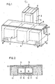
- Figure 1 shows a machine stand for a milling machine with high milling performance.
- the machine stand shown in the figure consists of an essentially cuboidal longitudinal part 2 and an essentially cuboidal tower part 3 connected to it in the material, both consisting essentially of acrylic concrete.
- the longitudinal part 2 like the tower part 3, contains cuboid inserts 4 made of polyurethane foam, which are cast in as a lost core during the manufacturing process in order to save material and significantly reduce the weight of the finished product.
- cuboid longitudinal part 2 and the tower part 3 plate-shaped steel inserts 5, 6 and 7 are cast in.
- inserts which are plate-shaped on the outside, serve to fasten further components.
- the feed unit of the milling machine is attached and rigidly fastened to it by a screw connection; to the steel inserts 6 of the main drive is flange-mounted on the feed device and on the two parallel plates 7, the F räs- is mounted spindle unit.
- the machine stand also has cast feet 9; Recesses 10 are provided above these feet, which on the one hand can facilitate transport and are also provided for receiving set screws through which the machines can be set up horizontally at the installation site.
- either the cuboidal longitudinal part 2 and the tower part 3 are cast in a common mold, or else the cuboidal longitudinal part 2 is cast in a mold and then after it has been cured, by means of cast an additional shape of the cuboid tower part 3 and thereby rigidly connected in the material.
- the plate-shaped steel inserts 5, 6 and 7 are inserted into the mold at the corresponding points; if appropriate, it may be expedient to fix the steel insert 6 and also the feet to the walls of the mold from the outside by screws.
- the mixture of additives and methacrylate resin is poured into the correspondingly prepared mold.
- the additives, the organic peroxide and the polymeric methacrylate resin powder are expediently premixed dry and this dry mixture is mixed with the low-viscosity methacrylate resin and mixed.
- the cuboid inserts 4 made of polyurethane foam are placed on it and then the mold is still filled to the intended height. If necessary, the machine stand with covered with a gelcoat.
- the acrylic concrete placed in the mold is compacted by vibration and possibly additional evacuation during insertion.
- the machine stand of a grinding machine shown in vertical section in FIG. 2 has a molded part 12 made of cast steel that delimits it in the upward direction and on both sides.
- the cavities located between the individual ribs of this molded part are filled with a layer 13 of acrylic concrete; the spaces between middle ribs are filled in the upper area by layers 14 and in the lower area by layers 15 made of acrylic concrete.
- the cavities 16 are either closed off by sheet metal 17 in such a way that no acrylic concrete can penetrate during the production of the layers 15, or are filled by inserted blocks of foam, for example polyurethane.
- welded steel structures can also be used, which is advantageous in some cases.
- the machine stand shown in vertical section in FIG. 2 is distinguished from the machine stands, which in the conventional way consist only of steel construction, primarily by the substantially higher damping and also by increased rigidity.
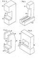
- FIG. 3 shows a machine stand made of acrylic concrete according to the invention, in which the upper part of the stand 24 projects laterally beyond the column 23, so that the lower part 22, the column 23 and the upper part 24 form an upright C.
- the lower stand part 22 there is a steel worktop (shown in a highly simplified form) on which the parts (not shown) required for operating the machine are then attached.
- FIG. 4 shows an embodiment similar to FIG. 3, but in which the lower stand part 22 'consists of an iron construction filled with methacrylate resin.
- two C-shaped stand consisting of lower stand part 22, column 23 and upper stand part 24 are combined by a worktop 26 to form a double stand.
- the worktop 26 can consist of acrylic concrete or of a steel structure, optionally filled with acrylic concrete.
- Fig. 6 shows a machine stand in a symmetrical embodiment, as a so-called portal shape.
- the lower stand part 22 and the upper stand part 24 are connected to one another by two columns 23.
- the upper part of the stand 24, the columns 23 and a strip 27 connecting them at the bottom are made in one piece, specifically in the material.
- a worktop 26 is also provided in this embodiment.
- the embodiment shown in FIG. 6 corresponds in terms of its shape to a combination of two C-shaped machine stands arranged in mirror image to one another.
- the lower stand part 22 and upper stand part 24 are connected by four columns 23 'made of acrylic concrete.
Landscapes
- Engineering & Computer Science (AREA)
- Chemical & Material Sciences (AREA)
- General Engineering & Computer Science (AREA)
- Mechanical Engineering (AREA)
- Ceramic Engineering (AREA)
- Chemical Kinetics & Catalysis (AREA)
- Materials Engineering (AREA)
- Structural Engineering (AREA)
- Organic Chemistry (AREA)
- Curing Cements, Concrete, And Artificial Stone (AREA)
- Addition Polymer Or Copolymer, Post-Treatments, Or Chemical Modifications (AREA)
Abstract
Description
Die Erfindung betrifft ein Verfahren zur Herstellung von Maschinenbauteilen, z.B. Maschinenständern mittels Polymerbeton auf der Basis von kalt härtendem Methacrylatharz und Zuschlagstoffen.The invention relates to a method for producing machine components, e.g. Machine stands using polymer concrete based on cold curing methacrylate resin and additives.
Es ist durch die DE-OS 27 43 396 bekannt, Maschinenständer für Werkzeugmaschinen aus einem Gemenge von Sand, Kies oder Schotter und einem ausgehärteten Mehrkomponentenkunststoff, z.B. Epo- xidharz oder Polyesterharz herzustellen. Bei diesem Herstellungsverfahren.haben sich jedoch manche Schwierigkeiten ergeben, welche bisher einer allgemeinen Einführung dieses Herstellungsverfahrens zur Erzeugung von Maschinenständern und dergleichen hinderlich waren.It is known from DE-OS 27 43 396, machine stand for machine tools of a mixture of sand, gravel or crushed stone and a cured multi-component plastic, eg e po- xidharz or produce polyester resin. However, there have been some difficulties in this manufacturing process which have hitherto hindered the general introduction of this manufacturing process for the production of machine stands and the like.
Durch die DE-AS 12 53 629 ist ein Verfahren zur Herstellung und Ausbesserung von Fahrbahndecken von Straßen, Flugplatzrollbahnen und dergleichen aus im wesentlichen körnigen Gesteinsmengen wie Splitt, Kies, Sand u.ä. durch Vermischen der genannten Straßenbaumaterialien mit Methacrylsäuremethylester, Auftragen dieses Gemisches auf den Straßenuntergrund bzw. auf die auszubessernde Stelle und Erhärten der Masse durch Polymerisation des Monomeren unter Einfluß eines bei normaler Temperatur wirksamen Beschleunigers bzw. Beschleunigersystems bekannt geworden. Bei diesem bekannten Verfahren wird dem Gesteinsmaterial ein in Methacrylsäuremethylester quellbares oder lösliches Polymerisat, insbesondere Polymethylmethacrylat, in feinverteilter Form zugesetzt und die Masse verarbeitet, ehe die Polymerisatteilchen vom Monomeren homogen durchgequollen oder in diesem aufgelöst sind.DE-AS 12 53 629 describes a method for producing and repairing road surfaces of roads, airport runways and the like from essentially granular rock quantities such as grit, gravel, sand and the like. by mixing the above-mentioned road building materials with methacrylic acid methyl ester, applying this mixture to the road surface or to the area to be repaired and hardening the mass by polymerizing the monomer under the influence of an accelerator or accelerator system effective at normal temperature. In this known method, a polymer which is swellable or soluble in methyl methacrylate, in particular polymethyl methacrylate, is added to the rock material in finely divided form and the mass is processed before the polymer particles are homogeneously swollen by or dissolved in the monomer.
Dieses bekannte Verfahren ist jedoch zur Herstellung von Maschinenständern und ähnlichen Produkten nicht geeignet, da die mechanischen Eigenschaften zwar für den angegebenen Zweck ausreichend sein können, keinesfalls jedoch für die bei Maschinenständern und ähnlichen Bauteilen auftretenden Beanspruchungen geeignet sind.However, this known method is not suitable for the production of machine stands and similar products, since the mechanical properties may be sufficient for the stated purpose, but are in no way suitable for the stresses which occur with machine stands and similar components.
Die Erfindung hat sich zur Aufgabe gestellt, durch spezielle Auswahl und Angabe der einzelnen Komponenten die Herstellung von hochwertigen Maschinenbauteilen, z.B.Maschinenständern aus Acrylbeton zu ermöglichen, die mechanischen Eigenschaften der Maschinenständer zu verbessern, insbesondere auch speziellen Anforderungen anzupassen und gegenüber bisherigen Herstellungsmethoden zu vereinfachen und zu verbilligen.The object of the invention is to enable the production of high-quality machine components, for example machine stands made of acrylic concrete, to improve the mechanical properties of the machine stands, in particular also to adapt to special requirements and to simplify and simplify them compared to previous production methods, by special selection and specification of the individual components cheaper.
Aufgrund zahlreicher Versuche wird bei einem Verfahren der eingangs genannten Art diese Aufgabe dadurch gelöst, daß das Harz mit einer dynamischen Viskosität von unter 10 mPas verwendet wird und dem Harz und/oder den Zuschlagstoffen als Startersystem wirkende Radikale, vorzugsweise ein organisches Peroxid und ein aromatisches tertiäres Amin oder ein organisches Metallsalz zugesetzt werden.Based on numerous tests, this object is achieved in a process of the type mentioned at the outset by using the resin with a dynamic viscosity of less than 10 mPas and radicals, preferably an organic peroxide and an aromatic tertiary, which act as a starter system for the resin and / or the additives Amine or an organic metal salt can be added.
Weitere Ausgestaltungen der Erfindung sind in den Unteransprüchen gekennzeichnet und werden nachstehend in Verbindung mit den Ausführungsbeispiele darstellenden, schematisch etwas vereinfacht gezeichneten Figuren näher beschrieben.Further refinements of the invention are characterized in the subclaims and are described in more detail below in connection with the figures which represent the exemplary embodiments and are shown schematically in somewhat simplified form.
Es zeigt:
- Fig. 1 einen Maschinenständer für eine Hochleistungsfräs- maschine in isometrischer Darstellung;
- Fig. 2 einen Vertikalschnitt durch einen Maschinenständer einer Schleifmaschine;
- Fig.3 einen erfindungsgemäß ausgebildeten Maschinenständer, bestehend aus Ständerunterteil, Säule und Ständeroberteil;
- Fig.4 eine Variante der in Fig.3 dargestellten Ausführungsform;
- Fig.5 eine weitere Variante der in Fig.3 dargestellten Ausführungsform; :
- Fig.6 eine erfindungsgemäße Ausführungsform, bei der Ständeroberteil und Ständerunterteil mit zwei Säulen verbunden sind;
- Fig.7 eine Variante der in Fig.6 dargestellten Ausführungsform mit vier Säulen zwischen Ständeroberteil und Ständerunterteil.
- 1 shows a machine stand for a high-performance milling machine in an isometric representation;
- 2 shows a vertical section through a machine stand of a grinding machine;
- 3 shows a machine stand designed according to the invention, consisting of the lower part of the stand, the column and the upper part of the stand;
- 4 shows a variant of the embodiment shown in Figure 3;
- 5 shows a further variant of the embodiment shown in FIG. 3; :
- 6 shows an embodiment according to the invention in which the upper stand part and lower stand part are connected with two columns;
- 7 shows a variant of the embodiment shown in FIG. 6 with four columns between the upper part of the stand and the lower part of the stand.
Figur 1 zeigt einen Maschinenständer für eine Fräsmaschine hoher Fräsleistung. Der in der Figur dargestellte Maschinenständer besteht aus einem im wesentlichen quaderförmigen Längsteil 2 und einem damit im Material verbundenen, im wesentlichen quaderförmigen Turmteil 3, beide im wesentlichen aus Acrylbeton bestehend. Der Längsteil 2 enthält, ebenso wie der Turmteil 3, quaderförmige Einlagen 4 aus Polyurethanschaum, welche beim Herstellungsverfahren als verlorener Kern mit eingegossen werden, um Material zu sparen und das Gewicht des fertigen Produktes wesentlich zu verringern.In den quaderförmigen Längsteil 2 und den Turmteil 3 sind plattenförmige Stahleinlagen 5, 6 und 7 eingegossen.Figure 1 shows a machine stand for a milling machine with high milling performance. The machine stand shown in the figure consists of an essentially cuboidal longitudinal part 2 and an essentially
Diese auf der Außenseite plattenförmig ausgebildeten Einlagen dienen zur Befestigung von weiteren Bauteilen. Auf die Stahleinlagen 5 wird die Vorschubeinheit der Fräsmaschine aufgesetzt und durch Schraubverbindung starr daran befestigt; an die Stahleinlagen 6 wird der Hauptantrieb für die Vorschubeinrichtung angeflanscht und an den beiden parallelen Platten 7 ist die Fräs- spindel-Einheit angebaut. Der Maschinenständer hat ferner eingegossene Füße 9; über diesen Füßen sind Aussparungen 10 vorgesehen, die einerseits den Transport erleichtern können und außerdem zur Aufnahme von Stellschrauben vorgesehen sind, durch welche die Maschinen am Aufstellungsort horizontal eingerichtet werden kann.These inserts, which are plate-shaped on the outside, serve to fasten further components. On the steel layers 5, the feed unit of the milling machine is attached and rigidly fastened to it by a screw connection; to the steel inserts 6 of the main drive is flange-mounted on the feed device and on the two
Zur Herstellung des in der Figur 1 in zum Teil schematisch vereinfachter Weise dargestellten Maschinenständers werden entweder der quaderförmige Längsteil 2 und der Turmteil 3 in einer gemeinsamen Form gegossen oder aber es wird zuerst der quaderförmige Längsteil 2 in einer Form gegossen und dann nach dessen Aushärtung wird mittels einer zusätzlichen Form der quaderförmige Turmteil 3 angegossen und dadurch starr im Material verbunden.For the manufacture of the machine stand shown in FIG. 1 in a partially schematically simplified manner, either the cuboidal longitudinal part 2 and the
Die plattenförmigen Stahleinlagen 5, 6 und 7 werden an den entsprechenden Stellen in die Form eingelegt; gegebenenfalls kann es zweckmäßig sein, die Stahleinlage 6 und auch die Füße an den Wänden der Form von außen auch durch Schrauben zu fixieren. In die entsprechend vorbereitete Form wird das Gemisch aus Zuschlagstoffen und Methacrylatharz eingegossen. Hierbei sind zweckmäßigerweise die Zuschlagstoffe, das organische Peroxid und das polymere Methacrylatharzpulver trocken vorgemischt und diese trockene Mischung wird mit dem eine niedrige Viskosität aufweisenden Methacrylatharz versetzt und vermischt. Zuerst wird in die Form nur ein Teil der Mischung eingegossen, darauf werden die quaderförmigen Einlagen 4 aus Polyurethanschaum aufgesetzt und dann wird die Form weiterhin bis zur vorgesehenen Höhe angefüllt. Gegebenenfalls wird der Maschinenständer mit einem überzug aus Gelcoat versehen. Der in die Form eingebrachte Acrylbeton wird während des Einbringens durch Vibration und eventuell zusätzliches Evakuieren verdichtet.The plate-
Der in Figur 2 im Vertikalschnitt dargestellte Maschinenständer einer Schleifmaschine hat einen diesen in Richtung nach oben und nach den beiden Seiten begrenzenden Formteil 12 aus Stahlguß. Die zwischen einzelnen Rippen dieses Formteiles befindlichen Hohlräume sind mit einer Schicht 13 aus Acrylbeton ausgegossen; die Räume zwischen mittleren Rippen sind im oberen Bereich durch Schichten 14 und im unteren Bereich durch Schichten 15 aus Acrylbeton ausgefüllt. Die Hohlräume 16 sind entweder durch Blecht.ei- le 17 derart abgeschlossen, daß bei der Herstellung der Schichten 15 kein Acrylbeton eindringen kann, oder sind durch eingesetzte Blöcke aus Schaumstoff, beispielsweise Polyurethan, gefüllt. Statt eines Formteiles aus Stahlguß können auch geschweißte Stahlkonstruktionen verwendet werden, was in manchen Fällen vorteilhaft ist.The machine stand of a grinding machine shown in vertical section in FIG. 2 has a molded
Der in Figur 2 im Vertikalschnitt dargestellte Maschinenständer zeichnet sich gegenüber den in konventioneller Weise nur aus Stahlkonstruktion bestehenden Maschinenständern vor allem durch die im wesentlichen höhere Dämpfung und auch durch erhöhte Steifigkeit aus.The machine stand shown in vertical section in FIG. 2 is distinguished from the machine stands, which in the conventional way consist only of steel construction, primarily by the substantially higher damping and also by increased rigidity.
In Figur 3 ist ein erfindungsgemäß aus Acrylbeton ausgeführter Maschinenständer dargestellt, bei dem Ständeroberteil 24 über die Säule 23 seitlich vorkragt, so daß Ständerunterteil 22, Säule 23 und Ständeroberteil 24 ein aufrecht stehendes C bilden. Hierbei befindet sich auf dem Ständerunterteil 22 eine (stark vereinfacht dargestellte) Arbeitsplatte 25 aus Stahl, auf der dann noch die zum Betrieb der Maschine erforderlichen, nicht dargestellten Teile befestigt werden.FIG. 3 shows a machine stand made of acrylic concrete according to the invention, in which the upper part of the
Fig.4 zeigt eine der Fig.3 ähnliche Ausführungsform, bei der jedoch der Ständerünterteil 22' aus einer mit Methacrylatharz ausgefüllten Eisenkonstruktion besteht.4 shows an embodiment similar to FIG. 3, but in which the lower stand part 22 'consists of an iron construction filled with methacrylate resin.
Bei der in Fig.5 dargestellten Ausführungsform sind zwei C-förmige, aus Ständerunterteil 22, Säule 23 und Ständeroberteil 24 bestehende, einzelne Ständer durch eine Arbeitsplatte 26 zu einem Doppelständer vereinigt. Die Arbeitsplatte 26 kann aus Acrylbeton bestehen oder aber auch aus einer - gegebenenfalls mit Acrylbeton ausgefüllten - Stahlkonstruktion.In the embodiment shown in FIG. 5, two C-shaped stand consisting of
Fig.6 zeigt einen Maschinenständer in symmetrischer Ausführungsform, als sogenannte Portalform. Bei dieser sind Ständerunterteil 22 und Ständeroberteil 24 durch zwei Säulen 23 miteinander verbunden. Bei dieser Ausführungsform sind Ständeroberteil 24, Säulen 23. und ein diese unten verbindender Streifen 27 einstückig, und zwar im Material verbunden hergestellt. Auch bei dieser Ausführungsform ist eine Arbeitsplatte 26 vorgesehen. Die in Fig.6 dargestellte Ausführungsform entspricht hinsichtlich ihrer Gestalt einer Kombination aus zwei spiegelbildlich zueinander angeordneten, C-förmigen Maschinenständern.Fig. 6 shows a machine stand in a symmetrical embodiment, as a so-called portal shape. In this, the
Bei der in Fig.7 dargestellten Portalform eines erfindungsgemäßen Maschinenständers sind Ständerunterteil 22 und Ständeroberteil 24 durch vier Säulen 23' aus Acrylbeton verbunden.In the portal shape of a machine stand according to the invention shown in FIG. 7, the
Das erfindungsgemäße Verfahren zur Herstellung von Maschinenständern aus Acrylbeton zeichnet sich durch nachstehende Vorzüge aus:
- 1. Die Geschwindigkeit des.Aushärtungsprozesses kann durch entsprechende Dosierung des Startersystems innerhalb verhältnismäßig breiter Grenzen verändert werden; so hat sich gezeigt, daß auch schon nach einer Stunde der Aushärteprozeß soweit beendet sein kann, daß der Maschinenständer aus der Form genommen werden kann. Infolgedessen kann auch mit nur einer Form bereits eine Serienproduktion durchgeführt werden. Dies ist im Hinblick auf die außerordentlich hohen Formkosten bei kompliziert gestalteten Maschinenständern von großer wirtschaftlicher Bedeutung.
- 2. Maschinenständer aus Acrylbeton bieten besonders günstige Möglichkeit, gewisse Bauteile als Grundtypen herzustellen und auf Lager zu fertigen. Es kann dann später durch zusätzliche Herstellung und Anbindung weiterer Bauteile eine Anpassung des Grundkörpers bzw. Ergänzung des Grundkörpers an die jeweilige Aufgabe bzw. den vorgesehenen speziellen Verwendungszweck erfolgen.
- 3. Gegenüber Maschinenständern aus Zementbeton bietet der erfindungsgemäß hergestellte Maschinenständer den Vorteil, daß er so gut wie keine Feuchtigkeit aufnimmt und deshalb auch nicht von aggressiven Medien, wie Bohrölemulsion, bei der Verwendung als Maschinenständer angegriffen wird.
- 4. Bemerkenswert ist ferner eine gegenüber Maschinenständern aus Grauguß oder Stahlguß oder geschweißten Stahlkonstruktionen wesentlich größere, mindestens sechsfach höhere Dämpfung, so daß beispielsweise bei der Bearbeitung von Drehteilen auch bei wesentlich erhöhter Spanleistung keine Rattermarken auftreten.
- 5. Maschinenständer, welche ein kalthärtendes Methacrylatharz mit einer dynamischen Viskosität von weniger als 10 mPas, vorzugsweise weniger als 2 mPas, enthalten, ergeben eine hohe Biegefestigkeit bei gleichzeitiger hoher Dämpfung. Dies ist insbesondere für die Säulen wichtig, weil diese auf Zugkräfte und bei C-Ständern auf Biegung beansprucht werden.
- 1. The speed of the curing process can be varied within a relatively wide range by appropriate metering of the starter system; it has been shown that the hardening process can be completed after just one hour so that the machine stand can be taken out of shape. As a result, series production can already be carried out with just one mold. This is of great economic importance in view of the extraordinarily high molding costs for complicatedly designed machine stands.
- 2. Machine stands made of acrylic concrete offer a particularly favorable possibility to manufacture certain components as basic types and to manufacture them in stock. It can then be done later by additional production and connection of further components, an adaptation of the base body or supplementation of the base body to the respective task or the intended special purpose.
- 3. Compared to machine stands made of cement concrete, the machine stand produced according to the invention has the advantage that it absorbs virtually no moisture and is therefore not attacked by aggressive media, such as oil emulsion, when used as a machine stand.
- 4. It is also noteworthy that the machine stands made of gray cast iron or cast steel or welded steel structures are significantly larger, at least six times higher damping, so that no chatter marks occur, for example, when machining turned parts, even when the chip output is significantly increased.
- 5. Machine stands which contain a cold-curing methacrylate resin with a dynamic viscosity of less than 10 mPas, preferably less than 2 mPas, result in a high flexural strength with high damping at the same time. This is particularly important for the pillars because they are subjected to tensile forces and, in the case of C-pillars, to bending.
Claims (14)
Priority Applications (1)
| Application Number | Priority Date | Filing Date | Title |
|---|---|---|---|
| AT81106294T ATE28812T1 (en) | 1980-08-16 | 1981-08-13 | PROCESS FOR MANUFACTURING MACHINE COMPONENTS, E.G. MACHINE STANDS. |
Applications Claiming Priority (4)
| Application Number | Priority Date | Filing Date | Title |
|---|---|---|---|
| DE3030914A DE3030914C2 (en) | 1980-08-16 | 1980-08-16 | Process for the production of machine frames using polymer concrete |
| DE3030914 | 1980-08-16 | ||
| DE8113100U | 1981-05-04 | ||
| DE8113100 | 1981-05-04 |
Publications (3)
| Publication Number | Publication Date |
|---|---|
| EP0046272A2 true EP0046272A2 (en) | 1982-02-24 |
| EP0046272A3 EP0046272A3 (en) | 1983-06-22 |
| EP0046272B1 EP0046272B1 (en) | 1987-08-12 |
Family
ID=25787254
Family Applications (1)
| Application Number | Title | Priority Date | Filing Date |
|---|---|---|---|
| EP81106294A Expired EP0046272B1 (en) | 1980-08-16 | 1981-08-13 | Method of manufacturing machine parts, e.g. machine tool columns |
Country Status (2)
| Country | Link |
|---|---|
| EP (1) | EP0046272B1 (en) |
| DE (1) | DE3176350D1 (en) |
Cited By (11)
| Publication number | Priority date | Publication date | Assignee | Title |
|---|---|---|---|---|
| GB2147026A (en) * | 1983-09-26 | 1985-05-01 | Muanyagipari Kutato Intezet | Externally reinforced polymer concrete structures |
| DE3514343A1 (en) * | 1985-04-19 | 1986-10-23 | Siemens AG, 1000 Berlin und 8000 München | Modular base frame |
| EP0211657A2 (en) * | 1985-08-07 | 1987-02-25 | Nippon Shokubai Co., Ltd. | Curable composition, method for manufacture thereof and articles made therefrom |
| WO1990005053A1 (en) * | 1988-11-03 | 1990-05-17 | Photec Industrie S.A. | Abrasion-type splitting unit |
| WO2000013843A1 (en) * | 1998-09-04 | 2000-03-16 | Terrence Sheehan | Reduced vibration lathe |
| WO2000045990A1 (en) * | 1999-02-01 | 2000-08-10 | Boehringer Werkzeugmaschinen Gmbh | Machine tool |
| EP1136182A1 (en) * | 2000-03-07 | 2001-09-26 | E. Siepmann & Co. (GmbH & Co.) | Twin grinding machine |
| FR2900919A1 (en) * | 2006-05-10 | 2007-11-16 | Forest Line Capdenac Soc Par A | Linear jig board for e.g. double guiding machine, has thick strip made of massive metal, where strip is supported on base by push jack and traction jack acting on height of strip, where jacks are provided at regular intervals |
| DE102012001621A1 (en) * | 2012-01-30 | 2013-08-01 | Heyligenstaedt Werkzeugmaschinen GmbH | Machine tool e.g. portal milling press tool for pressing e.g. autometal sheets in e.g. portal construction, has crossbeam that includes double walled cross beams which have cavity formed between walls and filled with concrete |
| CN105065864A (en) * | 2015-09-13 | 2015-11-18 | 金丽秋 | Fixing device for petroleum drilling diesel engine |
| CN112664759A (en) * | 2021-01-15 | 2021-04-16 | 李奇 | Agricultural machine field operation intelligent management ware |
Citations (10)
| Publication number | Priority date | Publication date | Assignee | Title |
|---|---|---|---|---|
| BE623314A (en) * | 1961-10-06 | |||
| DE1253629B (en) * | 1962-06-16 | 1967-11-02 | Roehm & Haas Gmbh | Process for the manufacture of road surface repairs |
| GB1163356A (en) * | 1966-05-17 | 1969-09-04 | Thiokol Chemical Corp | Bonding of Concrete |
| DE2222573A1 (en) * | 1971-05-10 | 1972-11-16 | Celmac Ag | Mortar - contg a polyester,a catalyst and a filler |
| DE2160612A1 (en) * | 1971-12-07 | 1973-06-20 | Degussa | Artificial resin bonded concrete - uses two stock solution binder |
| FR2188596A5 (en) * | 1972-06-12 | 1974-01-18 | Technosport | Soil coverings for sports grounds - contg. polyurethane resin, gives resilient surfaces |
| US3827933A (en) * | 1972-04-03 | 1974-08-06 | Du Pont | Filled polymethyl methacrylate article and a process for its manufacture |
| DE2508811A1 (en) * | 1974-03-05 | 1975-09-11 | Wienerberger Baustoffind Ag | Thin walled slender building parts prodn. - by moulding mixture of organic binder-(inorganic) filler in shaking rough-walled mould |
| FR2280608A1 (en) * | 1974-08-02 | 1976-02-27 | Asahi Glass Co Ltd | COMPOSITE NOISE ABSORPTION PRODUCT |
| CH612610A5 (en) * | 1976-03-23 | 1979-08-15 | Studer Ag Fritz | Machine stand for machine tools |
-
1981
- 1981-08-13 EP EP81106294A patent/EP0046272B1/en not_active Expired
- 1981-08-13 DE DE8181106294T patent/DE3176350D1/en not_active Expired
Patent Citations (10)
| Publication number | Priority date | Publication date | Assignee | Title |
|---|---|---|---|---|
| BE623314A (en) * | 1961-10-06 | |||
| DE1253629B (en) * | 1962-06-16 | 1967-11-02 | Roehm & Haas Gmbh | Process for the manufacture of road surface repairs |
| GB1163356A (en) * | 1966-05-17 | 1969-09-04 | Thiokol Chemical Corp | Bonding of Concrete |
| DE2222573A1 (en) * | 1971-05-10 | 1972-11-16 | Celmac Ag | Mortar - contg a polyester,a catalyst and a filler |
| DE2160612A1 (en) * | 1971-12-07 | 1973-06-20 | Degussa | Artificial resin bonded concrete - uses two stock solution binder |
| US3827933A (en) * | 1972-04-03 | 1974-08-06 | Du Pont | Filled polymethyl methacrylate article and a process for its manufacture |
| FR2188596A5 (en) * | 1972-06-12 | 1974-01-18 | Technosport | Soil coverings for sports grounds - contg. polyurethane resin, gives resilient surfaces |
| DE2508811A1 (en) * | 1974-03-05 | 1975-09-11 | Wienerberger Baustoffind Ag | Thin walled slender building parts prodn. - by moulding mixture of organic binder-(inorganic) filler in shaking rough-walled mould |
| FR2280608A1 (en) * | 1974-08-02 | 1976-02-27 | Asahi Glass Co Ltd | COMPOSITE NOISE ABSORPTION PRODUCT |
| CH612610A5 (en) * | 1976-03-23 | 1979-08-15 | Studer Ag Fritz | Machine stand for machine tools |
Cited By (13)
| Publication number | Priority date | Publication date | Assignee | Title |
|---|---|---|---|---|
| GB2147026A (en) * | 1983-09-26 | 1985-05-01 | Muanyagipari Kutato Intezet | Externally reinforced polymer concrete structures |
| DE3514343A1 (en) * | 1985-04-19 | 1986-10-23 | Siemens AG, 1000 Berlin und 8000 München | Modular base frame |
| EP0211657A2 (en) * | 1985-08-07 | 1987-02-25 | Nippon Shokubai Co., Ltd. | Curable composition, method for manufacture thereof and articles made therefrom |
| EP0211657A3 (en) * | 1985-08-07 | 1988-06-08 | Nippon Shokubai Kagaku Kogyo Co., Ltd | Curable composition, method for manufacture thereof and articles made therefrom |
| WO1990005053A1 (en) * | 1988-11-03 | 1990-05-17 | Photec Industrie S.A. | Abrasion-type splitting unit |
| US5099820A (en) * | 1988-11-03 | 1992-03-31 | Photec Industrie S.A. | Abrasion-type splitting unit |
| WO2000013843A1 (en) * | 1998-09-04 | 2000-03-16 | Terrence Sheehan | Reduced vibration lathe |
| WO2000045990A1 (en) * | 1999-02-01 | 2000-08-10 | Boehringer Werkzeugmaschinen Gmbh | Machine tool |
| EP1136182A1 (en) * | 2000-03-07 | 2001-09-26 | E. Siepmann & Co. (GmbH & Co.) | Twin grinding machine |
| FR2900919A1 (en) * | 2006-05-10 | 2007-11-16 | Forest Line Capdenac Soc Par A | Linear jig board for e.g. double guiding machine, has thick strip made of massive metal, where strip is supported on base by push jack and traction jack acting on height of strip, where jacks are provided at regular intervals |
| DE102012001621A1 (en) * | 2012-01-30 | 2013-08-01 | Heyligenstaedt Werkzeugmaschinen GmbH | Machine tool e.g. portal milling press tool for pressing e.g. autometal sheets in e.g. portal construction, has crossbeam that includes double walled cross beams which have cavity formed between walls and filled with concrete |
| CN105065864A (en) * | 2015-09-13 | 2015-11-18 | 金丽秋 | Fixing device for petroleum drilling diesel engine |
| CN112664759A (en) * | 2021-01-15 | 2021-04-16 | 李奇 | Agricultural machine field operation intelligent management ware |
Also Published As
| Publication number | Publication date |
|---|---|
| DE3176350D1 (en) | 1987-09-17 |
| EP0046272A3 (en) | 1983-06-22 |
| EP0046272B1 (en) | 1987-08-12 |
Similar Documents
| Publication | Publication Date | Title |
|---|---|---|
| DE3030914C2 (en) | Process for the production of machine frames using polymer concrete | |
| EP0046272A2 (en) | Method of manufacturing machine parts, e.g. machine tool columns | |
| EP1589050A1 (en) | Repair kit | |
| US4670208A (en) | Method of manufacturing machine supports by means of concrete polymer | |
| EP0204925B1 (en) | Building block | |
| DE3603527A1 (en) | METHOD FOR PRODUCING CAST MOLDS | |
| EP3705250B1 (en) | Method for producing a concrete component and concrete part producing device | |
| EP0054276A1 (en) | Process for making machine elements from synthetic concrete, as well as these elements, particularly supports for machine tools | |
| WO2007141214A2 (en) | Apparatus for producing moulded concrete bricks, mould for such an apparatus and process for producing such a mould | |
| EP0927207B1 (en) | Plastic moulded body | |
| DE8021861U1 (en) | Machine stand | |
| DE2160612A1 (en) | Artificial resin bonded concrete - uses two stock solution binder | |
| DE1683811A1 (en) | Process for the intensive processing of building material mixtures containing binding agents | |
| EP0299482A2 (en) | Process for the production of granules or formed bodies from powdery mineral materials | |
| DE4225333C2 (en) | Process for the production of moldings from waste rubber and moldings produced according to them | |
| DE3410751C2 (en) | Process for producing a matrix for the production of facade elements with a structured visible surface made of concrete | |
| EP0510486A1 (en) | Composite stone resp. composite plate | |
| EP0644024B1 (en) | Process and device for making cellular-concrete elements | |
| DE851476C (en) | Method and device for the production of concrete structural elements | |
| DE1694588C3 (en) | Process for the production of polishing media | |
| DE2546391A1 (en) | Centrifugally cast concrete pipe - produced from aggregates having controlled grain size distribution | |
| DE1759656A1 (en) | Procedure for supporting, shoring or bringing back-to-horizontal foundations of all kinds | |
| DE2313752A1 (en) | PROCESS FOR THE PRODUCTION OF MARBLE BLOCKS | |
| DE1922310A1 (en) | Plastic reinforced section honeycomb | |
| AT208282B (en) | Process for the production of shaped bodies from granular masses and extrusion press for carrying out the process |
Legal Events
| Date | Code | Title | Description |
|---|---|---|---|
| PUAI | Public reference made under article 153(3) epc to a published international application that has entered the european phase |
Free format text: ORIGINAL CODE: 0009012 |
|
| AK | Designated contracting states |
Designated state(s): AT BE CH DE FR GB IT LI NL SE |
|
| PUAL | Search report despatched |
Free format text: ORIGINAL CODE: 0009013 |
|
| AK | Designated contracting states |
Designated state(s): AT BE CH DE FR GB IT LI NL SE |
|
| 17P | Request for examination filed |
Effective date: 19830722 |
|
| GRAA | (expected) grant |
Free format text: ORIGINAL CODE: 0009210 |
|
| AK | Designated contracting states |
Kind code of ref document: B1 Designated state(s): AT BE CH DE FR GB IT LI NL SE |
|
| REF | Corresponds to: |
Ref document number: 28812 Country of ref document: AT Date of ref document: 19870815 Kind code of ref document: T |
|
| REF | Corresponds to: |
Ref document number: 3176350 Country of ref document: DE Date of ref document: 19870917 |
|
| PLBI | Opposition filed |
Free format text: ORIGINAL CODE: 0009260 |
|
| ET | Fr: translation filed | ||
| 26 | Opposition filed |
Opponent name: DEGUSSA AG, FRANKFURT - ZWEIGNIEDERLASSUNG WOLFGAN Effective date: 19870914 |
|
| ITF | It: translation for a ep patent filed | ||
| NLR1 | Nl: opposition has been filed with the epo |
Opponent name: DEGUSSA A.G. |
|
| PGFP | Annual fee paid to national office [announced via postgrant information from national office to epo] |
Ref country code: BE Payment date: 19890714 Year of fee payment: 9 |
|
| ITTA | It: last paid annual fee | ||
| PGFP | Annual fee paid to national office [announced via postgrant information from national office to epo] |
Ref country code: NL Payment date: 19890831 Year of fee payment: 9 Ref country code: GB Payment date: 19890831 Year of fee payment: 9 |
|
| PGFP | Annual fee paid to national office [announced via postgrant information from national office to epo] |
Ref country code: FR Payment date: 19900808 Year of fee payment: 10 |
|
| PGFP | Annual fee paid to national office [announced via postgrant information from national office to epo] |
Ref country code: SE Payment date: 19900809 Year of fee payment: 10 |
|
| PG25 | Lapsed in a contracting state [announced via postgrant information from national office to epo] |
Ref country code: GB Effective date: 19900813 |
|
| PG25 | Lapsed in a contracting state [announced via postgrant information from national office to epo] |
Ref country code: BE Effective date: 19900831 |
|
| BERE | Be: lapsed |
Owner name: KOBLISCHEK PETER Effective date: 19900831 |
|
| PG25 | Lapsed in a contracting state [announced via postgrant information from national office to epo] |
Ref country code: NL Effective date: 19910301 |
|
| GBPC | Gb: european patent ceased through non-payment of renewal fee | ||
| NLV4 | Nl: lapsed or anulled due to non-payment of the annual fee | ||
| PG25 | Lapsed in a contracting state [announced via postgrant information from national office to epo] |
Ref country code: SE Effective date: 19910814 |
|
| PG25 | Lapsed in a contracting state [announced via postgrant information from national office to epo] |
Ref country code: FR Effective date: 19920430 |
|
| REG | Reference to a national code |
Ref country code: FR Ref legal event code: ST |
|
| PGFP | Annual fee paid to national office [announced via postgrant information from national office to epo] |
Ref country code: AT Payment date: 19920812 Year of fee payment: 12 |
|
| PGFP | Annual fee paid to national office [announced via postgrant information from national office to epo] |
Ref country code: DE Payment date: 19920818 Year of fee payment: 12 |
|
| PGFP | Annual fee paid to national office [announced via postgrant information from national office to epo] |
Ref country code: CH Payment date: 19920821 Year of fee payment: 12 |
|
| PG25 | Lapsed in a contracting state [announced via postgrant information from national office to epo] |
Ref country code: AT Effective date: 19930813 |
|
| PG25 | Lapsed in a contracting state [announced via postgrant information from national office to epo] |
Ref country code: LI Free format text: LAPSE BECAUSE OF NON-PAYMENT OF DUE FEES Effective date: 19930831 Ref country code: CH Free format text: LAPSE BECAUSE OF NON-PAYMENT OF DUE FEES Effective date: 19930831 |
|
| REG | Reference to a national code |
Ref country code: CH Ref legal event code: PL |
|
| PG25 | Lapsed in a contracting state [announced via postgrant information from national office to epo] |
Ref country code: DE Effective date: 19940503 |
|
| EUG | Se: european patent has lapsed |
Ref document number: 81106294.2 Effective date: 19920306 |
|
| RDAG | Patent revoked |
Free format text: ORIGINAL CODE: 0009271 |
|
| STAA | Information on the status of an ep patent application or granted ep patent |
Free format text: STATUS: PATENT REVOKED |
|
| 27W | Patent revoked |
Effective date: 19951108 |
|
| APAH | Appeal reference modified |
Free format text: ORIGINAL CODE: EPIDOSCREFNO |