EP0046221B1 - Circuit commandé par thyristors pour la compensation rapide de puissance réactive - Google Patents
Circuit commandé par thyristors pour la compensation rapide de puissance réactive Download PDFInfo
- Publication number
- EP0046221B1 EP0046221B1 EP81105959A EP81105959A EP0046221B1 EP 0046221 B1 EP0046221 B1 EP 0046221B1 EP 81105959 A EP81105959 A EP 81105959A EP 81105959 A EP81105959 A EP 81105959A EP 0046221 B1 EP0046221 B1 EP 0046221B1
- Authority
- EP
- European Patent Office
- Prior art keywords
- thyristor
- arrangement
- fact
- reactive power
- controlled
- Prior art date
- Legal status (The legal status is an assumption and is not a legal conclusion. Google has not performed a legal analysis and makes no representation as to the accuracy of the status listed.)
- Expired
Links
Images

Classifications
-
- H—ELECTRICITY
- H02—GENERATION; CONVERSION OR DISTRIBUTION OF ELECTRIC POWER
- H02J—CIRCUIT ARRANGEMENTS OR SYSTEMS FOR SUPPLYING OR DISTRIBUTING ELECTRIC POWER; SYSTEMS FOR STORING ELECTRIC ENERGY
- H02J3/00—Circuit arrangements for ac mains or ac distribution networks
- H02J3/18—Arrangements for adjusting, eliminating or compensating reactive power in networks
- H02J3/1821—Arrangements for adjusting, eliminating or compensating reactive power in networks using shunt compensators
- H02J3/1835—Arrangements for adjusting, eliminating or compensating reactive power in networks using shunt compensators with stepless control
- H02J3/1864—Arrangements for adjusting, eliminating or compensating reactive power in networks using shunt compensators with stepless control wherein the stepless control of reactive power is obtained by at least one reactive element connected in series with a semiconductor switch
-
- Y—GENERAL TAGGING OF NEW TECHNOLOGICAL DEVELOPMENTS; GENERAL TAGGING OF CROSS-SECTIONAL TECHNOLOGIES SPANNING OVER SEVERAL SECTIONS OF THE IPC; TECHNICAL SUBJECTS COVERED BY FORMER USPC CROSS-REFERENCE ART COLLECTIONS [XRACs] AND DIGESTS
- Y02—TECHNOLOGIES OR APPLICATIONS FOR MITIGATION OR ADAPTATION AGAINST CLIMATE CHANGE
- Y02E—REDUCTION OF GREENHOUSE GAS [GHG] EMISSIONS, RELATED TO ENERGY GENERATION, TRANSMISSION OR DISTRIBUTION
- Y02E40/00—Technologies for an efficient electrical power generation, transmission or distribution
- Y02E40/10—Flexible AC transmission systems [FACTS]
Definitions
- the invention relates to a thyristor-based circuit arrangement for fast reactive power compensation.
- the choke coil which can be changed in inductance, can consist of two non-linear choke coils (saturation chokes) connected in series, of which one is connected in parallel with a thyristor controller, which consists of two anti-parallel connected and phase gated thyristors.
- the invention has for its object to provide a circuit arrangement in which the inductance variable inductor serves at the same time to adapt the compensation capacitor. This is based on the throttle circuit specified in EP-A1-37 027 (Article 54 (3) EPC).
- the object is achieved with a circuit arrangement according to claim 1 in that the two saturation inductors are provided with series-connected secondary windings which are used for transformer adaptation of the capacitor bank.
- a second solution to the problem uses a single saturation inductor with a split iron core according to the features of claim 6.
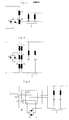
- the saturation choke coils 1, 2 in FIG. 1 are additionally provided with secondary windings 3, 4 connected in series, which serve for the transformer coupling of the capacitive compensator part 5.
- the thyristor controller 6, 7 can also be arranged parallel to the secondary winding 4 of the saturation inductor 2, as can be seen in FIG. 2.
- the thyristor controller 6, 7 is connected to a tertiary winding 10 of the saturation inductor 2.
- the secondary windings 3, 4 are replaced by taps 11, 12 on the secondary side.
- the secondary windings 3, 4 and 14 are also in series.
- the circuit arrangement can also be implemented with a single saturation inductor 15 by using a column iron core 18.
- the saturation choke coil 15 and the secondary winding 16 comprise the entire split core.
- the thyristor controller 6, 7 is connected in parallel to a tertiary winding 17, which comprises only part of the column iron core. By short-circuiting the winding 17 by means of the thyristor controller 6, 7, the magnetic resistance of the iron core 18 increases, causing it to saturate.
- a similar circuit arrangement is known from the ferroresonance transformers (US-A-3 579 088).
- the circuit arrangement according to FIG. 6, however, does not require any additional air gaps in the iron core, as are provided in the ferroresonance transformers.
- the circuit arrangement for fast reactive power compensation which has been provided for thyrists and which has so far only been considered in its single-phase version, can also be designed as a three-phase unit.
Landscapes
- Engineering & Computer Science (AREA)
- Power Engineering (AREA)
- Control Of Electrical Variables (AREA)
Claims (6)
Applications Claiming Priority (2)
| Application Number | Priority Date | Filing Date | Title |
|---|---|---|---|
| DE3030784A DE3030784C2 (de) | 1980-08-14 | 1980-08-14 | Schaltungsanordnung zur schnellen Blindleistungskompensation mit einem Transformator |
| DE3030784 | 1980-08-14 |
Publications (2)
| Publication Number | Publication Date |
|---|---|
| EP0046221A1 EP0046221A1 (fr) | 1982-02-24 |
| EP0046221B1 true EP0046221B1 (fr) | 1985-04-17 |
Family
ID=6109635
Family Applications (1)
| Application Number | Title | Priority Date | Filing Date |
|---|---|---|---|
| EP81105959A Expired EP0046221B1 (fr) | 1980-08-14 | 1981-07-29 | Circuit commandé par thyristors pour la compensation rapide de puissance réactive |
Country Status (2)
| Country | Link |
|---|---|
| EP (1) | EP0046221B1 (fr) |
| DE (1) | DE3030784C2 (fr) |
Families Citing this family (7)
| Publication number | Priority date | Publication date | Assignee | Title |
|---|---|---|---|---|
| EP0118418B1 (fr) * | 1982-09-06 | 1988-06-15 | Budapesti Müszaki Egyetem | Agencement de circuit servant a la compensation d'une puissance reactive a variation rapide, notamment au point de connexion d'appareils consommateurs d'energie produisant des harmoniques |
| JPS61109426A (ja) * | 1984-11-01 | 1986-05-27 | 三菱電機株式会社 | 静止形無効電力補償装置 |
| DE3616334C2 (de) * | 1986-05-15 | 2000-11-02 | Asea Brown Boveri | Verfahren zur Dämpfung mindestens einer elektrischen Oberschwingung zur Netzfrequenz in einem mehrphasigen Wechselstromnetz |
| DE19748147A1 (de) * | 1997-10-31 | 1999-05-06 | Asea Brown Boveri | Statischer Kompensator |
| DE102014106322B4 (de) * | 2014-05-06 | 2017-02-09 | Maschinenfabrik Reinhausen Gmbh | Anlage und Verfahren zum Bereitstellen von Blindleistung |
| DE102017121655A1 (de) * | 2017-09-19 | 2019-03-21 | Wobben Properties Gmbh | Windenergieanlage mit leistungsabhängiger Filtereinrichtung |
| CN111404172B (zh) * | 2020-03-30 | 2022-06-24 | 杭州银湖电气设备有限公司 | 一种基于高阻抗变压器的混合型动态无功补偿系统及方法 |
Family Cites Families (6)
| Publication number | Priority date | Publication date | Assignee | Title |
|---|---|---|---|---|
| US3184675A (en) * | 1960-07-11 | 1965-05-18 | Macklem F Sutherland | Gated control for power circuit |
| AT282001B (de) * | 1968-01-23 | 1970-06-10 | Elin Union Ag | Schaltungsanordnung für einen Serien-Schwingkreis |
| GB1230830A (fr) * | 1968-11-28 | 1971-05-05 | ||
| US3579088A (en) * | 1969-04-08 | 1971-05-18 | Taylor C Fletcher | Ferroresonant transformer with controllable flux |
| DE2008794A1 (de) * | 1970-02-21 | 1971-08-26 | Aei | Schaltungsanordnung zur Steuerung von Blindwiderstanden |
| DE3012015A1 (de) * | 1980-03-28 | 1981-10-15 | Licentia Patent-Verwaltungs-Gmbh, 6000 Frankfurt | Thyristorgestellte drosselspule |
-
1980
- 1980-08-14 DE DE3030784A patent/DE3030784C2/de not_active Expired
-
1981
- 1981-07-29 EP EP81105959A patent/EP0046221B1/fr not_active Expired
Also Published As
| Publication number | Publication date |
|---|---|
| EP0046221A1 (fr) | 1982-02-24 |
| DE3030784C2 (de) | 1986-09-11 |
| DE3030784A1 (de) | 1982-02-25 |
Similar Documents
| Publication | Publication Date | Title |
|---|---|---|
| DE2653333C2 (de) | Anordnung zur stufenlosen Kompensation von Blindleistung in einem elektrischen Wechselspannungsnetz | |
| EP0046221B1 (fr) | Circuit commandé par thyristors pour la compensation rapide de puissance réactive | |
| EP0026374B1 (fr) | Dispositif pour le transfert d'énergie électrique de grande puissance d'un réseau d'alimentation triphasé à fréquence plus élevée à un réseau de charge monophasé à fréquence plus basse | |
| DE2362375C2 (de) | Aus einem Wechselstromnetz gespeister steuer- und löschbarer Stromrichter für hohe Gleichstromwerte | |
| EP1310032B1 (fr) | Circuit pour la production statique d'une puissance electrique variable | |
| DE2456895A1 (de) | Phasenkompensationsanordnung | |
| EP0037027B1 (fr) | Disposition de bobines d'induction réglée par thyristors | |
| DE3213778C2 (fr) | ||
| DE3836698A1 (de) | Beschaltung fuer abschaltbare ventile | |
| EP0570839A2 (fr) | Circuit de compensation de chute de tension sur les lignes d'alimentation et pour la réduction des ondes harmoniques du courant électrique | |
| DE2832229C2 (de) | Thyristorgeschaltete Leistungskondensatoren oder Filterkreise | |
| DE1565273C3 (de) | Induktionsheizvorrichtung | |
| DE3021930A1 (de) | Netzgeraet | |
| DE3601990A1 (de) | Steuerverfahren fuer parallele thyristorgestellte induktivitaeten zur schnellen blindstromkompensation | |
| DE919181C (de) | Drehstromtransformator (oder -drossel) mit isoliertem Nullpunkt und einer eine Frequenzweiche enthaltenden, im offenen Dreieck geschalteten Hilfswicklung | |
| DE1136413B (de) | Anordnung zur Erzielung eines einwandfreien Parallelbetriebes selbstregelnder Synchrongeneratoren | |
| DE882878C (de) | Anordnung zur Steuerung eines Umrichters | |
| DE3045574A1 (de) | Statischer blindleistungskompensator | |
| DE1162943B (de) | Anordnung zur Blindstromkompensation von wechselstromgespeisten Hochstromoefen, insbesondere Drehstromlichtbogenoefen | |
| AT238328B (de) | Wechselstrom-Lichtbogenschweißvorrichtung mit mehreren, vorzugsweise gleichzeitig betriebenen Schweißelektroden | |
| DE730471C (de) | Anordnung zur Umwandlung von Wechselstrom konstanter Spannung in Wechselstrom konstanter Stromstaerke oder umgekehrt | |
| DE102018222183A1 (de) | Magnetisch regelbare Drosselspule in Reihenschaltung | |
| DE1638146A1 (de) | Gleichrichtergeraet | |
| DE1184413B (de) | Zweistufenschaltung von einphasigen Verbrauchern, z. B. von mit Netzfrequenz gespeisten Induktionsspulen | |
| CH401251A (de) | Einrichtung zur Speisung eines einphasigen Verbrauchers aus einem Mehrphasenwechselstromnetz vorgegebener Grundfrequenz |
Legal Events
| Date | Code | Title | Description |
|---|---|---|---|
| PUAI | Public reference made under article 153(3) epc to a published international application that has entered the european phase |
Free format text: ORIGINAL CODE: 0009012 |
|
| AK | Designated contracting states |
Designated state(s): BE CH FR GB LI SE |
|
| 17P | Request for examination filed |
Effective date: 19820603 |
|
| RAP1 | Party data changed (applicant data changed or rights of an application transferred) |
Owner name: TUTTAS, CHRISTIAN |
|
| GRAA | (expected) grant |
Free format text: ORIGINAL CODE: 0009210 |
|
| AK | Designated contracting states |
Designated state(s): BE CH FR GB LI SE |
|
| PG25 | Lapsed in a contracting state [announced via postgrant information from national office to epo] |
Ref country code: BE Effective date: 19850417 Ref country code: FR Free format text: THE PATENT HAS BEEN ANNULLED BY A DECISION OF A NATIONAL AUTHORITY Effective date: 19850417 |
|
| PG25 | Lapsed in a contracting state [announced via postgrant information from national office to epo] |
Ref country code: SE Effective date: 19850430 |
|
| PG25 | Lapsed in a contracting state [announced via postgrant information from national office to epo] |
Ref country code: CH Effective date: 19850731 Ref country code: LI Effective date: 19850731 |
|
| EN | Fr: translation not filed | ||
| PLBE | No opposition filed within time limit |
Free format text: ORIGINAL CODE: 0009261 |
|
| STAA | Information on the status of an ep patent application or granted ep patent |
Free format text: STATUS: NO OPPOSITION FILED WITHIN TIME LIMIT |
|
| GBPC | Gb: european patent ceased through non-payment of renewal fee | ||
| REG | Reference to a national code |
Ref country code: CH Ref legal event code: PL |
|
| 26N | No opposition filed | ||
| PG25 | Lapsed in a contracting state [announced via postgrant information from national office to epo] |
Ref country code: GB Effective date: 19881118 |