EP0046221B1 - Thyristor-controlled circuit for rapid compensation of reactive power - Google Patents
Thyristor-controlled circuit for rapid compensation of reactive power Download PDFInfo
- Publication number
- EP0046221B1 EP0046221B1 EP81105959A EP81105959A EP0046221B1 EP 0046221 B1 EP0046221 B1 EP 0046221B1 EP 81105959 A EP81105959 A EP 81105959A EP 81105959 A EP81105959 A EP 81105959A EP 0046221 B1 EP0046221 B1 EP 0046221B1
- Authority
- EP
- European Patent Office
- Prior art keywords
- thyristor
- arrangement
- fact
- reactive power
- controlled
- Prior art date
- Legal status (The legal status is an assumption and is not a legal conclusion. Google has not performed a legal analysis and makes no representation as to the accuracy of the status listed.)
- Expired
Links
Images

Classifications
-
- H—ELECTRICITY
- H02—GENERATION; CONVERSION OR DISTRIBUTION OF ELECTRIC POWER
- H02J—CIRCUIT ARRANGEMENTS OR SYSTEMS FOR SUPPLYING OR DISTRIBUTING ELECTRIC POWER; SYSTEMS FOR STORING ELECTRIC ENERGY
- H02J3/00—Circuit arrangements for ac mains or ac distribution networks
- H02J3/18—Arrangements for adjusting, eliminating or compensating reactive power in networks
- H02J3/1821—Arrangements for adjusting, eliminating or compensating reactive power in networks using shunt compensators
- H02J3/1835—Arrangements for adjusting, eliminating or compensating reactive power in networks using shunt compensators with stepless control
- H02J3/1864—Arrangements for adjusting, eliminating or compensating reactive power in networks using shunt compensators with stepless control wherein the stepless control of reactive power is obtained by at least one reactive element connected in series with a semiconductor switch
-
- Y—GENERAL TAGGING OF NEW TECHNOLOGICAL DEVELOPMENTS; GENERAL TAGGING OF CROSS-SECTIONAL TECHNOLOGIES SPANNING OVER SEVERAL SECTIONS OF THE IPC; TECHNICAL SUBJECTS COVERED BY FORMER USPC CROSS-REFERENCE ART COLLECTIONS [XRACs] AND DIGESTS
- Y02—TECHNOLOGIES OR APPLICATIONS FOR MITIGATION OR ADAPTATION AGAINST CLIMATE CHANGE
- Y02E—REDUCTION OF GREENHOUSE GAS [GHG] EMISSIONS, RELATED TO ENERGY GENERATION, TRANSMISSION OR DISTRIBUTION
- Y02E40/00—Technologies for an efficient electrical power generation, transmission or distribution
- Y02E40/10—Flexible AC transmission systems [FACTS]
Definitions
- the invention relates to a thyristor-based circuit arrangement for fast reactive power compensation.
- the choke coil which can be changed in inductance, can consist of two non-linear choke coils (saturation chokes) connected in series, of which one is connected in parallel with a thyristor controller, which consists of two anti-parallel connected and phase gated thyristors.
- the invention has for its object to provide a circuit arrangement in which the inductance variable inductor serves at the same time to adapt the compensation capacitor. This is based on the throttle circuit specified in EP-A1-37 027 (Article 54 (3) EPC).
- the object is achieved with a circuit arrangement according to claim 1 in that the two saturation inductors are provided with series-connected secondary windings which are used for transformer adaptation of the capacitor bank.
- a second solution to the problem uses a single saturation inductor with a split iron core according to the features of claim 6.
- the saturation choke coils 1, 2 in FIG. 1 are additionally provided with secondary windings 3, 4 connected in series, which serve for the transformer coupling of the capacitive compensator part 5.
- the thyristor controller 6, 7 can also be arranged parallel to the secondary winding 4 of the saturation inductor 2, as can be seen in FIG. 2.
- the thyristor controller 6, 7 is connected to a tertiary winding 10 of the saturation inductor 2.
- the secondary windings 3, 4 are replaced by taps 11, 12 on the secondary side.
- the secondary windings 3, 4 and 14 are also in series.
- the circuit arrangement can also be implemented with a single saturation inductor 15 by using a column iron core 18.
- the saturation choke coil 15 and the secondary winding 16 comprise the entire split core.
- the thyristor controller 6, 7 is connected in parallel to a tertiary winding 17, which comprises only part of the column iron core. By short-circuiting the winding 17 by means of the thyristor controller 6, 7, the magnetic resistance of the iron core 18 increases, causing it to saturate.
- a similar circuit arrangement is known from the ferroresonance transformers (US-A-3 579 088).
- the circuit arrangement according to FIG. 6, however, does not require any additional air gaps in the iron core, as are provided in the ferroresonance transformers.
- the circuit arrangement for fast reactive power compensation which has been provided for thyrists and which has so far only been considered in its single-phase version, can also be designed as a three-phase unit.
Description
Die Erfindung bezieht sich auf eine thyristorgestellte Schaltungsanordnung zur schnellen Blindleistungskompensation.The invention relates to a thyristor-based circuit arrangement for fast reactive power compensation.
Bei Anordnungen zur schnellen Blindleistungskompensation ist es bekannt, einen Parallelschwingkreis zu verwenden, welcher aus einer festen Kondensator- oder Filterbatterie und einer in ihrer Induktivität veränderbaren Drosselspule besteht. Die in ihrer Induktivität veränderbare Drosselspule kann nach der gemäß Artikel 54(3) EPÜ zum Stand der Technik gehörenden Europäischen Anmeldung 81 102 084.1 (veröffentlicht durch EP-A1-37 027) aus zwei in Reihe geschalteten nichtlinearen Drosselspulen (Sättigungsdrosseln) bestehen, von denen eine mit einem Thyristorsteller parallel geschaltet ist, der aus zwei antiparallel geschalteten und phasenanschnittgesteuerten Thyristoren besteht.In the case of arrangements for fast reactive power compensation, it is known to use a parallel resonant circuit which consists of a fixed capacitor or filter battery and a choke coil which can be changed in its inductance. According to the
Bei hohen Spannungen ist es oft zweckmäßig, die Kondensatorbatterie nicht direkt, sondern über einen Anpaßtransformator an das Netz zu schalten. Der Erfindung liegt die Aufgabe zugrunde, eine Schaltungsanordnung zu schaffen, in der die in ihrer Induktivität veränderbare Drosselspule gleichzeitig zur Anpassung des Kompensationskondensators dient. Dabei wird von der in der EP-A1-37 027 angegebenen Drosselschaltung ausgegangen (Artikel 54(3) EPÜ).At high voltages, it is often advisable not to connect the capacitor bank to the mains directly, but rather via a matching transformer. The invention has for its object to provide a circuit arrangement in which the inductance variable inductor serves at the same time to adapt the compensation capacitor. This is based on the throttle circuit specified in EP-A1-37 027 (Article 54 (3) EPC).
Die Aufgabe wird erfindungsgemäß mit einer Schaltungsanordnung gemäß Anspruch 1 dadurch gelöst, daß die beiden Sättigungsdrosselspulen mit in Reihe geschalteten Sekundärwicklungen versehen werden, die zur transformatorischen Anpassung der Kondensatorbatterie dienen.The object is achieved with a circuit arrangement according to
Eine zweite Lösung der Aufgabe verwendet eine einzige Sättigungsdrosselspule mit einem Spalteisenkern gemäß den Merkmalen des Anspruchs 6.A second solution to the problem uses a single saturation inductor with a split iron core according to the features of claim 6.
Zweckmäßige Weiterbildungen der Erfindung sind den abhängigen Ansprüchen zu entnehmen.Appropriate developments of the invention can be found in the dependent claims.
Die durch die Erfindung erzielten Vorteile bestehen insbesondere darin, daß auf einen zusätzlichen Anpaßtransformator für die Kondensatorbatterie verzichtet werden kann.The advantages achieved by the invention consist in particular in the fact that an additional matching transformer for the capacitor bank can be dispensed with.
Die Erfindung wird nachstehend anhand von in der Zeichnung schematisch dargestellten Ausführungsbeispielen erläutert.The invention is explained below with reference to exemplary embodiments shown schematically in the drawing.
Es zeigt
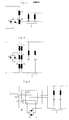
- Fig. 1 eine grundsätzliche Ausbildung der erfindungsgemäßen Schaltungsanordnung mit Thyristorsteller in einphasiger Ausführung,
- Fig. 2 eine abweichende Ausbildung der erfindungsgemäßen Schaltungsanordnung,
- Fig. 3 eine andere Ausbildung der Schaltungsanordnung,
- Fig. 4 eine weitere Ausbildung der Schaltungsanordnung,
- Fig.5 eine weitere Ausbildung der Schaltungsanordnung,
- Fig. 6 eine thyristorgestellte Schaltungsanordnung mit einer Sättigungsdrosselspule auf einem Spalteisenkern.
- 1 shows a basic design of the circuit arrangement according to the invention with a thyristor controller in a single-phase design,
- 2 shows a different design of the circuit arrangement according to the invention,
- 3 shows another embodiment of the circuit arrangement,
- 4 shows a further embodiment of the circuit arrangement,
- 5 shows a further embodiment of the circuit arrangement,
- Fig. 6 shows a thyristor-based circuit arrangement with a saturation inductor on a column iron core.
Die Ausbildung nach Fig. 1 besteht aus zwei in Reihe geschalteten Sättigungsdrosselspulen 1, 2. Parallel zur Sättigungsdrosselspule 2 liegt ein an sich bekannter Thyristorsteller, der aus den antiparallelen Thyristoren 6, 7 besteht, welche über ihre Gates 8, gezündet werden (Phasenanschnittsteuerung). Die bislang beschriebene Anordnung und ihre Wirkungsweise gehören durch die EP-A1-37 027 zum Stand der Technik. Im Gegensatz zu diesem Dokument sind die Sättigungsdrosselspulen 1, 2 in Fig. 1 zusätzlich mit in Reihe geschalteten Sekundärwicklungen 3, 4 versehen, die zur transformatorischen Ankopplung des kapazitiven Kompensatorteiles 5 dienen.1 consists of two
Der Thyristorsteller 6, 7 kann auch parallel zur Sekundärwicklung 4 der Sättigungsdrosselspule 2 angeordnet sein, wie der Fig. 2 zu entnehmen ist.The
Bei der Ausbildung nach der Fig. 3 ist der Thyristorsteller 6, 7 an einer Tertiärwicklung 10 der Sättigungsdrosselspule 2 angeschlossen.3, the
Bei der Ausbildung nach der Fig.4 sind die Sekundärwicklungen 3, 4 durch sekundärseitige Anzapfungen 11, 12 ersetzt.In the embodiment according to FIG. 4, the
Mit den Sättigungsdrosselspulen 1, 2 können weitere Sättigungsdrosseln in Reihe geschaltet werden. Bei der Ausbildung nach Fig. 5 ist zusätzlich zu den Drosseln 1 und 2 eine Drossel 13 in Reihe geschaltet.With the
Die Sekundärwicklungen 3, 4 und 14 liegen ebenfalls in Reihe.The
Wie aus Fig. 6 ersichtlich, ist die Schaltungsanordnung auch mit einer einzigen Sättigungsdrosselspule 15 realisierbar, indem ein Spalteisenkern 18 verwendet ist. Die Sättigungsdrosselspule 15 sowie die Sekundärwicklung 16 umfassen den gesamten Spaltkern. Der Thyristorsteller 6, 7 ist parallel zu einer Tertiärwicklung 17 geschaltet, die nur einen Teil des Spalteisenkernes umfaßt. Durch Kurzschließen der Wicklung 17 mittels des Thyristorstellers 6, 7 erhöht sich der magnetische Widerstand des Eisenkernes 18, wodurch dieser in die Sättigung geht. Eine ähnliche Schaltungsanordnung ist von den Ferroresonanz-Transformatoren her bekannt (US-A-3 579 088). Die Schaltungsanordnung nach Fig. 6 benötigt jedoch keine zusätzlichen Luftspalte im Eisenkern, wie sie bei den Ferroresonanz-Transformatoren vorgesehen sind.As can be seen from FIG. 6, the circuit arrangement can also be implemented with a
Die thyristorgestellte Schaltungsanordnung zur schnellen Blindleistungskompensation, die bislang nur in ihrer einphasigen Ausführung betrachtet wurde, ist sinngemäß auch als Dreiphaseneinheit ausbildbar.The circuit arrangement for fast reactive power compensation, which has been provided for thyrists and which has so far only been considered in its single-phase version, can also be designed as a three-phase unit.
Claims (6)
Applications Claiming Priority (2)
| Application Number | Priority Date | Filing Date | Title |
|---|---|---|---|
| DE3030784 | 1980-08-14 | ||
| DE3030784A DE3030784C2 (en) | 1980-08-14 | 1980-08-14 | Circuit arrangement for fast reactive power compensation with a transformer |
Publications (2)
| Publication Number | Publication Date |
|---|---|
| EP0046221A1 EP0046221A1 (en) | 1982-02-24 |
| EP0046221B1 true EP0046221B1 (en) | 1985-04-17 |
Family
ID=6109635
Family Applications (1)
| Application Number | Title | Priority Date | Filing Date |
|---|---|---|---|
| EP81105959A Expired EP0046221B1 (en) | 1980-08-14 | 1981-07-29 | Thyristor-controlled circuit for rapid compensation of reactive power |
Country Status (2)
| Country | Link |
|---|---|
| EP (1) | EP0046221B1 (en) |
| DE (1) | DE3030784C2 (en) |
Families Citing this family (7)
| Publication number | Priority date | Publication date | Assignee | Title |
|---|---|---|---|---|
| WO1984001059A1 (en) * | 1982-09-06 | 1984-03-15 | Budapesti Mueszaki Egyetem | Circuit arrangement for compensation of fast changing reactive power, in particular on the point of consumers, which generate harmonics |
| JPS61109426A (en) * | 1984-11-01 | 1986-05-27 | 三菱電機株式会社 | Static type reactive power compensator |
| DE3616334C2 (en) * | 1986-05-15 | 2000-11-02 | Asea Brown Boveri | Method of damping at least one electrical harmonic at the mains frequency in a multi-phase AC network |
| DE19748147A1 (en) * | 1997-10-31 | 1999-05-06 | Asea Brown Boveri | Static compensator for reactive power compensation in electrical power supply network |
| DE102014106322B4 (en) * | 2014-05-06 | 2017-02-09 | Maschinenfabrik Reinhausen Gmbh | Plant and method for providing reactive power |
| DE102017121655A1 (en) * | 2017-09-19 | 2019-03-21 | Wobben Properties Gmbh | Wind energy plant with power-dependent filter device |
| CN111404172B (en) * | 2020-03-30 | 2022-06-24 | 杭州银湖电气设备有限公司 | Mixed type dynamic reactive power compensation system and method based on high-impedance transformer |
Family Cites Families (6)
| Publication number | Priority date | Publication date | Assignee | Title |
|---|---|---|---|---|
| US3184675A (en) * | 1960-07-11 | 1965-05-18 | Macklem F Sutherland | Gated control for power circuit |
| AT282001B (en) * | 1968-01-23 | 1970-06-10 | Elin Union Ag | Circuit arrangement for a series resonant circuit |
| GB1230830A (en) * | 1968-11-28 | 1971-05-05 | ||
| US3579088A (en) * | 1969-04-08 | 1971-05-18 | Taylor C Fletcher | Ferroresonant transformer with controllable flux |
| DE2008794A1 (en) * | 1970-02-21 | 1971-08-26 | Aei | Circuit arrangement for controlling reactances |
| DE3012015A1 (en) * | 1980-03-28 | 1981-10-15 | Licentia Patent-Verwaltungs-Gmbh, 6000 Frankfurt | THYRISTOR-SET THROTTLE COIL |
-
1980
- 1980-08-14 DE DE3030784A patent/DE3030784C2/en not_active Expired
-
1981
- 1981-07-29 EP EP81105959A patent/EP0046221B1/en not_active Expired
Also Published As
| Publication number | Publication date |
|---|---|
| EP0046221A1 (en) | 1982-02-24 |
| DE3030784A1 (en) | 1982-02-25 |
| DE3030784C2 (en) | 1986-09-11 |
Similar Documents
| Publication | Publication Date | Title |
|---|---|---|
| DE2653333C2 (en) | Arrangement for stepless compensation of reactive power in an electrical AC voltage network | |
| EP0046221B1 (en) | Thyristor-controlled circuit for rapid compensation of reactive power | |
| EP0026374B1 (en) | Device for transferring high-power electric energy from a higher frequency three-phase supply network to a lower frequency single-phase load network | |
| DE2362375C2 (en) | Controllable and erasable power converters for high direct current values, fed from an alternating current network | |
| EP1310032B1 (en) | Circuit arrangement for the static generation of a variable electric output | |
| DE2456895A1 (en) | PHASE COMPENSATION ARRANGEMENT | |
| EP0037027B1 (en) | Thyristor controlled inductor arrangement | |
| DE3213778C2 (en) | ||
| DE3836698A1 (en) | CIRCUIT FOR SHUTDOWN VALVES | |
| EP0570839A2 (en) | Voltage drop compensating and current harmonics reducing circuit on the feed lines | |
| DE2832229C2 (en) | Thyristor-switched power capacitors or filter circuits | |
| DE1565273C3 (en) | Induction heater | |
| DE3021930A1 (en) | POWER SUPPLY | |
| DE3601990A1 (en) | CONTROL METHOD FOR PARALLEL THYRISTOR-SET INDUCTIVES FOR FAST BLIND CURRENT COMPENSATION | |
| DE919181C (en) | Three-phase transformer (or choke) with isolated zero point and an auxiliary winding containing a crossover, connected in an open delta | |
| DE741172C (en) | Device for the control or for the direct operation of apparatus used for voltage regulation | |
| DE1136413B (en) | Arrangement to achieve perfect parallel operation of self-regulating synchronous generators | |
| DE882878C (en) | Arrangement for controlling a converter | |
| DE3045574A1 (en) | Static reactive power compensator coupled to transformer secondary - has additional transformer between mains transformer secondary and thyristor chokes, with phase-variable secondaries | |
| DE1162943B (en) | Arrangement for reactive current compensation of AC powered high-current furnaces, especially three-phase arc furnaces | |
| AT238328B (en) | AC arc welding device with several welding electrodes, preferably operated simultaneously | |
| DE730471C (en) | Arrangement for converting alternating current of constant voltage into alternating current of constant current strength or vice versa | |
| DE102018222183A1 (en) | Magnetically adjustable choke coil in series connection | |
| DE1638146A1 (en) | Rectifier device | |
| DE1184413B (en) | Two-stage switching of single-phase consumers, e.g. B. from induction coils fed with mains frequency |
Legal Events
| Date | Code | Title | Description |
|---|---|---|---|
| PUAI | Public reference made under article 153(3) epc to a published international application that has entered the european phase |
Free format text: ORIGINAL CODE: 0009012 |
|
| AK | Designated contracting states |
Designated state(s): BE CH FR GB LI SE |
|
| 17P | Request for examination filed |
Effective date: 19820603 |
|
| RAP1 | Party data changed (applicant data changed or rights of an application transferred) |
Owner name: TUTTAS, CHRISTIAN |
|
| GRAA | (expected) grant |
Free format text: ORIGINAL CODE: 0009210 |
|
| AK | Designated contracting states |
Designated state(s): BE CH FR GB LI SE |
|
| PG25 | Lapsed in a contracting state [announced via postgrant information from national office to epo] |
Ref country code: BE Effective date: 19850417 Ref country code: FR Free format text: THE PATENT HAS BEEN ANNULLED BY A DECISION OF A NATIONAL AUTHORITY Effective date: 19850417 |
|
| PG25 | Lapsed in a contracting state [announced via postgrant information from national office to epo] |
Ref country code: SE Effective date: 19850430 |
|
| PG25 | Lapsed in a contracting state [announced via postgrant information from national office to epo] |
Ref country code: CH Effective date: 19850731 Ref country code: LI Effective date: 19850731 |
|
| EN | Fr: translation not filed | ||
| PLBE | No opposition filed within time limit |
Free format text: ORIGINAL CODE: 0009261 |
|
| STAA | Information on the status of an ep patent application or granted ep patent |
Free format text: STATUS: NO OPPOSITION FILED WITHIN TIME LIMIT |
|
| GBPC | Gb: european patent ceased through non-payment of renewal fee | ||
| REG | Reference to a national code |
Ref country code: CH Ref legal event code: PL |
|
| 26N | No opposition filed | ||
| PG25 | Lapsed in a contracting state [announced via postgrant information from national office to epo] |
Ref country code: GB Effective date: 19881118 |