EP0045901A1 - Elongate fixture for lighting work areas - Google Patents
Elongate fixture for lighting work areas Download PDFInfo
- Publication number
- EP0045901A1 EP0045901A1 EP81105981A EP81105981A EP0045901A1 EP 0045901 A1 EP0045901 A1 EP 0045901A1 EP 81105981 A EP81105981 A EP 81105981A EP 81105981 A EP81105981 A EP 81105981A EP 0045901 A1 EP0045901 A1 EP 0045901A1
- Authority
- EP
- European Patent Office
- Prior art keywords
- transverse
- angle
- grid
- lamellae
- lamp according
- Prior art date
- Legal status (The legal status is an assumption and is not a legal conclusion. Google has not performed a legal analysis and makes no representation as to the accuracy of the status listed.)
- Granted
Links
Images


Classifications
-
- F—MECHANICAL ENGINEERING; LIGHTING; HEATING; WEAPONS; BLASTING
- F21—LIGHTING
- F21V—FUNCTIONAL FEATURES OR DETAILS OF LIGHTING DEVICES OR SYSTEMS THEREOF; STRUCTURAL COMBINATIONS OF LIGHTING DEVICES WITH OTHER ARTICLES, NOT OTHERWISE PROVIDED FOR
- F21V11/00—Screens not covered by groups F21V1/00, F21V3/00, F21V7/00 or F21V9/00
- F21V11/02—Screens not covered by groups F21V1/00, F21V3/00, F21V7/00 or F21V9/00 using parallel laminae or strips, e.g. of Venetian-blind type
-
- F—MECHANICAL ENGINEERING; LIGHTING; HEATING; WEAPONS; BLASTING
- F21—LIGHTING
- F21S—NON-PORTABLE LIGHTING DEVICES; SYSTEMS THEREOF; VEHICLE LIGHTING DEVICES SPECIALLY ADAPTED FOR VEHICLE EXTERIORS
- F21S8/00—Lighting devices intended for fixed installation
-
- F—MECHANICAL ENGINEERING; LIGHTING; HEATING; WEAPONS; BLASTING
- F21—LIGHTING
- F21Y—INDEXING SCHEME ASSOCIATED WITH SUBCLASSES F21K, F21L, F21S and F21V, RELATING TO THE FORM OR THE KIND OF THE LIGHT SOURCES OR OF THE COLOUR OF THE LIGHT EMITTED
- F21Y2103/00—Elongate light sources, e.g. fluorescent tubes
Definitions
- the invention relates to an elongated workplace lamp according to the preamble of claim 1.
- Such a lamp and its assignment to a work table is known from US Pat. No. 3,389,246: It is arranged along a longitudinal edge of the rectangular work table, above and opposite the person working on this table. Direct glare is avoided by using a conventional grid with vertical transverse slats. However, a considerable proportion of light strikes the working area of the table top at such an angle that it is reflected from there into the eye of the person working at the table; as a result, the contrast of the visual task is at least reduced, and, with a correspondingly high luminance, even causes reflex glare, which in any case leads to impaired visual performance.
- the invention is therefore based on the object of avoiding such an impairment in an arrangement of lamp and table according to the preamble of the main claim.
- the invention ensures that all light rays striking the table have a minimum inclination to the vertical determined by the overlap; This can be dimensioned so that from the work surface of the table or a vision lying on it task no rays are reflected in the eye of the person sitting at the table.
- the workstation lamp is to be used in a room with VDU workstations, adequate shielding must also be ensured: Above a shielding angle ⁇ the lamp must appear dark, ie the luminance must be equal to or less than 200 candelas per square meter The arrangement of the screen workstations to each other and to the lights means that the shielding angle is 75 ° or 65 °.
- the distance between two adjacent transverse lamellae is chosen so large that the angle of the boundary beam measured through the upper and lower edges of the adjacent transverse lamellae is equal to or smaller than the required shielding angle.
- cross-blades with a bent profile, the lower part of which has an angle of inclination with respect to the horizontal that is equal to or smaller than the required shielding angle.
- the workstation lamp is mirror-inverted in the same way as the central transverse symmetry plane.
- the work area therefore receives light from both outer sections of the workplace lamp, the end areas of the table, however, from the middle section. In this way not only a better use of the lamp power but also an increase in the contrast in the work area is achieved.
- bent cross blades with or without intermediate blades In the middle section of the luminaire, the undersides of the bent cross blades are not reflective or black, and the relationships discussed above also apply.
- the shielding angle as the highest limit has already been mentioned if the workplace lights are to be used in rooms with VDU workstations.
- a value is preferably chosen for this angle of inclination which lies between the limits specified in claim 9.
- the workplace lamp has an upper light outlet opening through which the direct radiation of the upper half of the lamp is also transmitted can emerge upwards together with the above-mentioned reflected light and thus serves the general lighting of the room. Under certain circumstances, additional ceiling lights can even be omitted.
- FIGS. 1a and 1b show a rectangular desk 1 and above it the workstation lamp 2 with the length L shown in FIG. 3, indicated here only by dashed lines.
- the lamp extends over the entire length of the desk and runs parallel to its longitudinal edge and its table surface at a vertical distance H from the table surface or about 1.85 m above the floor, so that there is practically no view of the upper light outlet opening ( 220 in FIG. 3) is possible.
- the lamp 2 is arranged above the rear quarter of the table top. If a normal grid were used, the light coming from the luminaire would be redirected directly into the eye of the person sitting at the table through a reflective work surface in the work area e and cause a reduction in contrast or reflected glare (see dash-dotted beam path). This is prevented by the invention with the aid of the grid 20 with inclined transverse slats 201, 202.
- This grid 20 is indicated schematically in FIG. 1a and has four sections a to d, with sections c and d being mirror images of the other half with sections a and b.
- the undersides of the transverse slats in sections b and c are black, those of the transverse slats in sections a and d are mirrored; the length of the two middle sections is denoted by 1.
- the beam paths shown in dashed lines in FIG. 1a show that the working field e with the width E of the the two outer sections a and d of the lamp, while the outer areas g and f of the table are illuminated by the inner sections b and c.
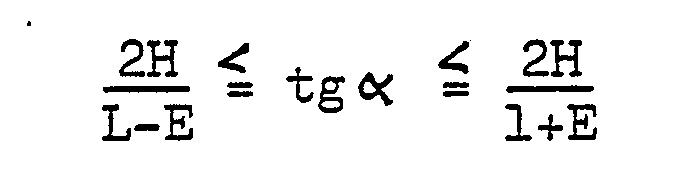
- the light rays hit the table top at an angle that lies between the angles ⁇ and ⁇ of the two boundary rays through the upper and lower edges of adjacent transverse slats.
- the work area is thus primarily illuminated by light from the side, so that light reflected from the work area e cannot strike the eye of the person working at the table.
- this template is symmetrical to the transverse symmetry plane 200; if these optimal conditions are also to apply when the work template is shifted by a distance s, then 1 must also be chosen to be larger by the same amount - if necessary in both directions.
- the latter is again equal to or smaller than the maximum permissible shielding angle ⁇ , so that no light can be reflected from the lower part 2022 'of the right lamella, which has a larger angle than 6.
- the distance A between two adjacent transverse lamellae 202 ' is, on the other hand, dimensioned so large that the angle ⁇ of the boundary beam passing through the lower edge of the right transverse lamella is also equal to or smaller than the shielding angle ⁇ : in this way, a shielding angle which is sufficient in many applications with VDU workstations can be achieved guarantee of 75 °.
- an auxiliary lamella 203 ' can be provided in the middle between the upper parts 2021' of two adjacent transverse lamellas 202 ', which is non-reflective (black) at the top and bottom and their size and angle of inclination is equal to the size and the angle of inclination of the upper parts 2021 'of the transverse lamella 202': this auxiliary lamella also keeps scattered light reflected from the shielding area repeatedly between adjacent transverse lamellae.
- the undersides of the cross blades in the central section 1 of the grid of the workstation lamp are non-reflective (black).
- the lamp 2 shown in cross section in FIG. 3 also has a light exit opening 220 on the upper side;
- the grid 20 described is arranged in the lower light exit opening 210.
- Two asymmetrical channel mirrors 23 and associated fluorescent lamps 221, 222 are arranged in the housing 21 of the workplace lamp.
- the rear mirror parts 232 have such a main emission direction ⁇ and curvature that they appear dark from a normal sitting position, but nevertheless direct the majority of the light into the front area of the work table (FIG. 1b); the front mirror parts 231, on the other hand, direct the light into the central and rear areas of the table.
- the mirror parts 231, 232 only extend to the level of the central plane of the fluorescent lamps and there are at a distance from these lamps through which light reflected by the grid 20 can exit.
- the light emitted by the upper half of the lamps is also emitted unhindered against the ceiling of the room.
Abstract
Description
Die Erfindung betrifft eine langgestreckte Arbeitsplatzleuchte gemäß Oberbegriff von Anspruch 1.The invention relates to an elongated workplace lamp according to the preamble of claim 1.
Eine derartige Leuchte und ihre Zuordnung zu einem Arbeitstisch ist aus der US-PS 3 389 246 bekannt: Sie ist entlang einer Längskante des rechteckigen Arbeitstisches angeordnet, und zwar oberhalb und gegenüber der an diesem Tisch arbeitenden Person. Eine Direktblendung ist dabei durch ein übliches Raster mit vertikalen Querlamellen vermieden. Ein erheblicher Lichtanteil trifft jedoch mit einem solchen Winkel auf das Arbeitsfeld der Tischplatte auf, daß es von dort gerade in das Auge der am Tisch arbeitenden Person reflektiert wird; dadurch wird zumindest der Kontrast der Sehaufgabe gemindert, bei entsprechend hoher Leuchtdichte sogar Reflexblendung-verursacht, was in jedem Fall zu einer Beeinträchtigung der Sehleistung führt. Der Erfindung liegt-daher die Aufgabe zugrunde, eine derartige Beeinträchtigung bei einer Anordnung von Leuchte und Tisch gemäß Oberbegriff des Hauptanspruches zu vermeiden.Such a lamp and its assignment to a work table is known from US Pat. No. 3,389,246: It is arranged along a longitudinal edge of the rectangular work table, above and opposite the person working on this table. Direct glare is avoided by using a conventional grid with vertical transverse slats. However, a considerable proportion of light strikes the working area of the table top at such an angle that it is reflected from there into the eye of the person working at the table; as a result, the contrast of the visual task is at least reduced, and, with a correspondingly high luminance, even causes reflex glare, which in any case leads to impaired visual performance. The invention is therefore based on the object of avoiding such an impairment in an arrangement of lamp and table according to the preamble of the main claim.
Die erfindungsgemäße Lösung dieser Aufgabe ist durch die im Anspruch 1 angegebenen Merkmale gekennzeichnet.The achievement of this object is characterized by the features specified in claim 1.
Durch die Erfindung ist sichergestellt, daß alle auf den Tisch auftreffenden Lichtstrahlen eine durch die Überlappung bestimmte Mindestneigung gegen die Vertikale aufweisen; diese läßt sich so bemessen, daß von der Arbeitsfläche des Tisches bzw. einer darauf liegenden Sehaufgabe keine Strahlen in das Auge der am Tisch sitzenden Person reflektiert werden.The invention ensures that all light rays striking the table have a minimum inclination to the vertical determined by the overlap; This can be dimensioned so that from the work surface of the table or a vision lying on it task no rays are reflected in the eye of the person sitting at the table.
Sofern'die Arbeitsplatzleuchte in einem Raum benützt werden soll, in dem sich Bildschirmarbeitsplätze befinden, ist zusätzlich eine ausreichende Abschirmung sicherzustellen: Oberhalb eines Abschirmwinkels ε muß die Leuchte dunkel erscheinen, d.h., die Leuchtdichte gleich oder kleiner 200 Candela pro Quadratmeter sein.. Je nach der Anordnung der Bildschirmarbeitsplätze zueinander und zu den Leuchten liegt dieser Abschirmwinkel bei 75°oder 65°.If the workstation lamp is to be used in a room with VDU workstations, adequate shielding must also be ensured: Above a shielding angle ε the lamp must appear dark, ie the luminance must be equal to or less than 200 candelas per square meter The arrangement of the screen workstations to each other and to the lights means that the shielding angle is 75 ° or 65 °.
Um diese zusätzliche Abschirmbedingung zu erfüllen, ist gemäß einer Weiterbildung der Erfindung der Abstand zweier benachbarter Querlamellen so groß gewählt, daß' der gegen die Vertikale gemessene Winkel des durch Ober- und Unterkanten der benachbarten Querlamellen gehenden Grenzstrahles gleich oder kleiner als der geforderte Abschirmwinkel ist.In order to meet this additional shielding condition, according to a further development of the invention, the distance between two adjacent transverse lamellae is chosen so large that the angle of the boundary beam measured through the upper and lower edges of the adjacent transverse lamellae is equal to or smaller than the required shielding angle.
Um hierbei mit möglichst wenig Querlamellen und damit geringen Verlusten auszukommen, ist es besonders vorteilhaft, Querlamellen mit einem geknickten Profil zu verwenden, deren Unterteil einen Neigungswinkel gegen die Hori- zontale hat, der gleich oder kleiner als der geforderte Abschirmwinkel ist.In order to get by with as few cross-blades as possible and thus low losses, it is particularly advantageous to use cross-blades with a bent profile, the lower part of which has an angle of inclination with respect to the horizontal that is equal to or smaller than the required shielding angle.
Bei höchsten Anforderungen an die Abschirmung (Abschirmwinkel = 650) können sich Formen und Abemessungen für die geknickten Querlamellen ergeben, die hinsichtlich Aufwand und Wirkungsgrad ungünstig sind. Zweckmäßiger ist es, in diesem-Fall mittig zwischen den Oberteilen zweier benachbarter, geknickter Querlamellen eine Hilfslamelle einzufügen, die beidseitig nicht reflektierend, insbesondere schwarz, ausgebildet ist und deren Größe und Neigungswinkel gleich der Größe und dem Neigungswinkel des Oberteiles einer Querlamelle ist.At the highest requirements of the shielding (cut-off = 65 0) located shapes and Abemessungen may arise for the bent transverse lamellae, which in terms of effort and efficiency are unfavorable. It is more expedient in this case to insert an auxiliary lamella in the middle between the upper parts of two adjacent, bent transverse lamellae, which is not reflective on both sides, in particular black, and its size and inclination angle kel is equal to the size and angle of inclination of the upper part of a cross lamella.
Im Interesse einer möglichst optimalen Nutzung des Lichtes der Arbeitsplatzleuchte ist es vorteilhaft, das Arbeitsfeld des Tisches von beiden Hälften der Leuchte überlappend auszuleuchten. Gemäß einer Weiterbildung der Erfindung wird dies dadurch erreicht, daß die Arbeitsplatzleuchte spiegelbildlich gleich zur mittleren Quersymmetrieebene ausgebildet ist. Das Arbeitsfeld erhält daher Licht von beiden äußeren Abschnitten der Arbeitsplatzleuchte, die Endbereiche des Tisches dagegen von dem mittleren Abschnitt. Auf diese Weise wird nicht nur eine bessere Nutzung der Lampenleistung sondern darüberhinaus auch eine Erhöhung des Kontrastes im Arbeitsfeld erreicht.In the interest of the best possible use of the light from the workplace lamp, it is advantageous to illuminate the working area of the table overlapping from both halves of the lamp. According to a development of the invention, this is achieved in that the workstation lamp is mirror-inverted in the same way as the central transverse symmetry plane. The work area therefore receives light from both outer sections of the workplace lamp, the end areas of the table, however, from the middle section. In this way not only a better use of the lamp power but also an increase in the contrast in the work area is achieved.
Eine weitere Verbesserung besteht schließlich darin, die Unterseite der Querlamellen wenigstens im mittleren Abschnitt der Leuchte nicht reflektierend, insbesondere schwarz, auszubilden. Optimale Verhältnisse sind dabei zu erzielen, wenn man die Länge dieses mittleren Abschnittes und die Größe der Überlappung der Querlamellen nach den in Unteranspruch 8 angegebenen Beziehungen wählt: Es gibt dann auch kein an der Unterseite des Rasters reflektiertes Licht, das im Arbeitsfeld des Tisches Kontrastminderung oder gar Reflexblendung verursachen könnte.Finally, a further improvement is to make the underside of the transverse slats non-reflective, in particular black, at least in the central section of the lamp. Optimal conditions can be achieved if one chooses the length of this middle section and the size of the overlap of the transverse lamellas according to the relationships specified in subclaim 8: There is then also no light reflected on the underside of the grid, which reduces contrast or in the working area of the table could even cause reflex glare.
Dies gilt auch bei Verwendung von geknickten Querlamellen mit oder ohne dazwischen liegenden Hilfslamellen: Im mittleren Abschnitt der Leuchte sind die Unterseiten der geknickten Querlamellen nicht reflektierend bzw. schwarz ausgeführt und es gelten im übrigen die besprochenen Beziehungen.This also applies when using bent cross blades with or without intermediate blades: In the middle section of the luminaire, the undersides of the bent cross blades are not reflective or black, and the relationships discussed above also apply.
Für den Neigungswinkel der Querlamellen bzw. der Unterteile von geknickten Querlamellen wurde bereits der AbschirmwinkelaLs oberster Grenzwert genannt, wenn die Arbeitsplatzleuchten in Räumen mit Bildschirmarbeitsplätzen Verwendung finden sollen. Durch eine entsprechende Wahl des Neigungswinkels läßt sich jedoch auch eine besonders wirksame Ausleuchtung des Arbeitsfeldes durch die beiden äußeren Abschnitte der Leuchte gewährleisten. Hierzu wird für diesen Neigungswinkel vorzugsweise ein Wert gewählt, der zwischen den in Anspruch 9 angegebenen Grenzen liegt.For the angle of inclination of the transverse slats or the lower parts of bent transverse slats, the shielding angle as the highest limit has already been mentioned if the workplace lights are to be used in rooms with VDU workstations. Through a corresponding choice of the angle of inclination, however, particularly effective illumination of the working area by the two outer sections of the lamp can also be ensured. For this purpose, a value is preferably chosen for this angle of inclination which lies between the limits specified in claim 9.
An den Oberseiten der schräggestellten Querlamellen wird ein Teil- des von der Lampe ausgehenden Lichtstromes nach oben reflektiert: Um auch diesen Anteil nutzen zu können, hat die Arbeitsplatzleuchte gemäß einer Weiterbildung der Erfindung eine obere Lichtaustrittsöffnung, durch die auch die Direktstrahlung der oberen Hälfte der Lampe zusammen mit dem erwähnten reflektierten Licht nach oben austreten kann und somit der allgemeinen Beleuchtung des Raumes dient. Dabei kann unter Umständen sogar auf - zusätzliche Deckenleuchten verzichtet werden.Part of the luminous flux emanating from the lamp is reflected upwards on the upper sides of the inclined transverse lamellae: In order to be able to use this share, too, according to a further development of the invention, the workplace lamp has an upper light outlet opening through which the direct radiation of the upper half of the lamp is also transmitted can emerge upwards together with the above-mentioned reflected light and thus serves the general lighting of the room. Under certain circumstances, additional ceiling lights can even be omitted.
Besonders vorteilhaft sind in diesem Zusammenhang dreilampige Leuchten, von denen die mittlere, über einem L-förmigen Steg angeordnete Lampe nur nach oben strahlt und von den beiden anderen Lampen getrennt schaltbar ist. Anhand eines derartigen Ausführungsbeispieles wird die Erfindung näher erläutert; es zeigen
- FIG 1a eine Frontansicht eines Arbeitstisches mit darüber angeordneter Leuchte,
- FIG 1b eine Seitenansicht von Tisch und Leuchte in Richtung des Pfeiles I in FIG 1a,
- FIG 2 einen Ausschnitt aus dem Raster der Leuchte,
- FIG 3 einen Querschnitt durch die Arbeitsplatzleuchte entlang Linie III-III in FIG 1a, und
- FIG 4 einen Ausschnitt aus einem Raster mit geknickten Lamellen.
- 1a shows a front view of a work table with a lamp arranged above it,
- 1b shows a side view of the table and lamp in the direction of arrow I in FIG. 1a,
- 2 shows a section of the grid of the lamp,
- 3 shows a cross section through the working p latzleuchte along line III-III in FIG 1a, and
- 4 shows a section of a grid with bent slats.
In den FIG 1a und 1b ist ein rechteckiger Schreibtisch 1 und darüber die in FIG 3 dargestellte, hier nur gestrichelt angedeutete Arbeitsplatzleuchte 2 mit der Länge L gezeigt. Die Leuchte erstreckt sich etwa über die gesamte Länge des Schreibtisches und verläuft parallel zu dessen Längskante und seiner Tischfläche und zwar in einem vertikalen Abstand H von der Tischfläche bzw. etwa 1,85m über dem Boden, so daß praktisch kein Einblick in die obere Lichtaustrittsöffnung (220 in FIG 3) möglich ist.FIGS. 1a and 1b show a rectangular desk 1 and above it the
Aus FIG 1b ist ersichtlich, daß die Leuchte 2 oberhalb des hinteren Viertels der Tischplatte angeordnet ist. Bei Verwendung eines gewöhnlichen Rasters würde hierbei das von der Leuchte kommende Licht durch eine reflektierende Arbeitsunterlage im Arbeitsfeld e direkt in das Auge der am Tisch sitzenden Person umgelenkt und eine Kontrastminderung oder Reflexblendung verursachen (vgl. strichpunktierter Strahlengang). Dies wird durch die Erfindung mit Hilfe des Rasters 20 mit schräggestellten Querlamellen 201, 202 verhindert. Dieses Raster 20 ist in FIG 1a schematisch angedeutet und hat vier Abschnitte a bis d, wobei die Abschnitte c und d spiegelbildlich gleich der anderen Hälfte mit den Abschnitten a und b ist. Die Unterseiten der Querlamellen in den Abschnitten b und c sind schwarz, die der Querlamellen in den Abschnitten a und d spiegelnd ausgebildet; die Länge der beiden mittleren Abschnitte ist mit 1 bezeichnet.From Figure 1b it can be seen that the
Die in FIG 1a gestrichelt eingetragenen Strahlengänge zeigen, daß das Arbeitsfeld e mit der Breite E von den beiden äußeren Abschnitten a und d der Leuchte, die Aussenbereiche g und f des Tisches dagegen von den inneren Abschnitten b und c ausgeleuchtet werden. Die Lichtstrahlen treffen dabei unter einem Winkel auf die Tischplatte, der zwischen den Winkeln ß und γ der beiden Grenzstrahlen durch Ober- und Unterkanten benachbarter Querlamellen liegt. Das Arbeitsfeld wird somit in erster Linie durch seitlich einfallendes Licht ausgeleuchtet, so daß vom Arbeitsfeld e reflektiertes Licht nicht das Auge der am Tisch arbeitenden Person treffen kann.The beam paths shown in dashed lines in FIG. 1a show that the working field e with the width E of the the two outer sections a and d of the lamp, while the outer areas g and f of the table are illuminated by the inner sections b and c. The light rays hit the table top at an angle that lies between the angles β and γ of the two boundary rays through the upper and lower edges of adjacent transverse slats. The work area is thus primarily illuminated by light from the side, so that light reflected from the work area e cannot strike the eye of the person working at the table.
Das gilt streng genommen nur, wenn im Bereich der inneren Abschnitte b und c der Leuchte kein Lichtstrahl durch das Raster austreten kann, der in einer vertikalen, zur Leuchtenachse senkrechten Ebene liegt. Um dies zu gewährleisten, sind die Unterseiten der Lamellen 202, 201 in dem mittleren Abschnitt schwarz ausgeführt und sie überlappen sich gegenseitig, wie dies aus FIG 2 zu ersehen ist: Bei gegebener Höhe x des Rasters 20 und einer Höhe h der Augen P über der Tischfläche gelten für die Überlappung y benachbarter Lamellen und für die Länge 1 der mittleren Abschnitte b, c des Rasters die Bedingungen
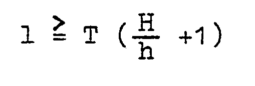
Diese Bedingungen gelten auch bei Verwendung eines Rasters 20' mit geknickten Lamellen 202' gemäß FIG 4. Die Querlamellen 202'bestehen dabei jeweils aus einem Unterteil 2022' mit einem Neigungswinkel α gegen die Horizontale und einem Oberteil 2021' mit einem Neigungswinkel α', der kleiner als « ist. Letzterer ist wiederum gleich oder kleiner als der maximal zulässige Abschirmwinkel ε, so daß von dem Unterteil 2022' der rechten Lamelle kein Licht nach links reflektiert werden kann, das einen größeren Winkel als 6 hat. Der Abstand A zweier benachbarter Querlamellen 202' ist andererseits so groß bemessen, daß der Winkel ß des durch die Unterkante der rechten Querlamelle verlaufenden Grenzstrahles ebenfalls gleich oder kleiner als der Abschirmwinkel ε ist: Auf diese Weise läßt sich ein in vielen Anwendungsfällen mit Bildschirmarbeitsplätzen ausreichender Abschirmwinkel von 75° gewährleisten.These conditions also apply when using a grid 20 'with kinked slats 202' according to FIG. 4. The transverse slats 202 'each consist of a lower part 2022' with an angle of inclination α relative to the horizontal and an upper part 2021 'with an angle of inclination α' is less than «. The latter is again equal to or smaller than the maximum permissible shielding angle ε, so that no light can be reflected from the lower part 2022 'of the right lamella, which has a larger angle than 6. The distance A between two adjacent transverse lamellae 202 'is, on the other hand, dimensioned so large that the angle β of the boundary beam passing through the lower edge of the right transverse lamella is also equal to or smaller than the shielding angle ε: in this way, a shielding angle which is sufficient in many applications with VDU workstations can be achieved guarantee of 75 °.
Sind noch strengere Abschirmbedingungen (ε = 65°) zu erfüllen, so kann hierzu mittig zwischen den Oberteilen 2021' zweier benachbarter Querlamellen 202' eine Hilfslamelle 203' vorgesehen werden, die oben und unten nicht reflektierend (schwarz) ausgebildet ist und deren Größe und Neigungswinkel gleich der Größe und dem Neigungswinkel der Oberteile 2021' der Querlamellen 202' ist: Durch diese Hilfslamelle wird auch mehrfach zwischen benachbarten Querlamellen reflektiertes Streulicht aus dem Abschirmbereich herausgehalten.If even stricter shielding conditions (ε = 65 °) have to be met, an auxiliary lamella 203 'can be provided in the middle between the upper parts 2021' of two adjacent transverse lamellas 202 ', which is non-reflective (black) at the top and bottom and their size and angle of inclination is equal to the size and the angle of inclination of the upper parts 2021 'of the transverse lamella 202': this auxiliary lamella also keeps scattered light reflected from the shielding area repeatedly between adjacent transverse lamellae.
Auch bei Verwendung eines derartigen Rasters mit geknickten Querlamellen mit oder ohne dazwischen angeordneten Hilfslamellen werden die Unterseiten der Querlamellen in dem mittleren Abschnitt 1 des Rasters der Arbeitsplatzleuchte nicht reflektierend (schwarz) ausgeführt.Even when using such a grid with kinked cross blades with or without auxiliary blades arranged in between, the undersides of the cross blades in the central section 1 of the grid of the workstation lamp are non-reflective (black).
Die geneigten Querlamellen reflektieren mit ihren Oberseiten einen Teil des Lichtes nach oben. Um auch dieses nutzen zu können, hat die in FIG 3 im Querschnitt dargestellte Leuchte 2 auch auf der Oberseite eine Lichtaustrittsöffnung 220; in der unteren Lichtaustrittsöffnung 210 ist das beschriebene Raster 20 angeordnet. In dem Gehäuse 21 der Arbeitsplatzleuchte sind zwei asymmetrische Rinnenspiegel 23 und zugeordnete Leuchtstofflampen 221, 222 angeordnet. Die hinteren Spiegelteile 232 haben eine solche Hauptausstrahlungsrichtung ß und Krümmung, daß sie aus normaler Sitzposition dunkel erscheinen, trotzdem aber den überwiegenden Anteil des Lichtes in den vorderen Bereich des Arbeitstisches (FIG 1b) lenken; die vorderen Spiegelteile 231 lenken das Licht dagegen in den mittleren und hinteren Bereich des Tisches.The inclined transverse slats reflect part of the light upwards with their tops. In order to be able to use this as well, the
Die Spiegelteile 231, 232 reichen nur bis auf die Höhe der Mittelebene der Leuchtstofflampen und weisen dort von diesen Lampen einen Abstand auf, durch den vom Raster 20 nach oben reflektiertes Licht austreten kann. Das von der oberen Hälfte der Lampen emittierte Licht wird ebenfalls unbehindert gegen die Decke des Raumes abgestrahlt.The
Zwischen den beiden Rinnenspiegeln 23 besteht ein V-förmiger Steg, in dem Vorschaltgeräte untergebracht sind. Ferner ist oberhalb dieses Steges eine weitere Leuchtstofflampe 223 und zwischen ihr und diesem Steg ein nach oben strahlender Rinnenspiegel 230 angeordnet: Mit dieser auch getrennt schaltbaren Lampe 223 läßt sich - auch bei abgeschalteten Lampen 221, 222 - eine ausreichende Allgemeinbeleuchtung sicherstellen, die ihrerseits nur eine gleichmäßigere Ausleuchtung der gesamten Tischfläche zur Folge hat.Between the two channel mirrors 23 there is a V-shaped web in which ballasts are accommodated. Furthermore, a further fluorescent lamp 223 is arranged above this web and a channel mirror 230 radiating upwards is arranged between it and this web: With this lamp 223, which can also be switched separately, sufficient general lighting can be ensured, even when
Claims (10)


Priority Applications (1)
| Application Number | Priority Date | Filing Date | Title |
|---|---|---|---|
| AT81105981T ATE4346T1 (en) | 1980-08-08 | 1981-07-29 | EXTENDED WORKPLACE LIGHT. |
Applications Claiming Priority (2)
| Application Number | Priority Date | Filing Date | Title |
|---|---|---|---|
| DE3030080 | 1980-08-08 | ||
| DE3030080A DE3030080C2 (en) | 1980-08-08 | 1980-08-08 | Elongated workplace lamp |
Publications (2)
| Publication Number | Publication Date |
|---|---|
| EP0045901A1 true EP0045901A1 (en) | 1982-02-17 |
| EP0045901B1 EP0045901B1 (en) | 1983-07-27 |
Family
ID=6109209
Family Applications (1)
| Application Number | Title | Priority Date | Filing Date |
|---|---|---|---|
| EP81105981A Expired EP0045901B1 (en) | 1980-08-08 | 1981-07-29 | Elongate fixture for lighting work areas |
Country Status (5)
| Country | Link |
|---|---|
| EP (1) | EP0045901B1 (en) |
| AT (1) | ATE4346T1 (en) |
| DE (1) | DE3030080C2 (en) |
| FI (1) | FI66482C (en) |
| ZA (1) | ZA815470B (en) |
Cited By (1)
| Publication number | Priority date | Publication date | Assignee | Title |
|---|---|---|---|---|
| EP3859200A1 (en) * | 2020-01-31 | 2021-08-04 | Bartenbach Holding GmbH | Illumination device |
Families Citing this family (6)
| Publication number | Priority date | Publication date | Assignee | Title |
|---|---|---|---|---|
| AT376784B (en) * | 1982-01-18 | 1984-12-27 | Zumtobel Ag | WORKPLACE LIGHT |
| DE3412162C1 (en) * | 1984-03-31 | 1985-08-29 | Trilux-Lenze Gmbh + Co Kg, 5760 Arnsberg | Elongated lamp |
| DE3711366A1 (en) * | 1987-04-04 | 1988-10-27 | Pohlschroeder & Co Kg | Louvered luminaire for workplaces |
| DE9101774U1 (en) * | 1991-02-15 | 1991-05-08 | Siemens Ag, 8000 Muenchen, De | |
| DE4111577A1 (en) * | 1991-04-10 | 1992-10-15 | Trilux Lenze Gmbh & Co Kg | Work place light housing with lower housing opening - has downwardly open reflector unit supported via rigid support edge, upper housing opening serving for lamp and reflector unit exchange |
| DE29608354U1 (en) * | 1996-05-08 | 1996-06-27 | Trilux Lenze Gmbh & Co Kg | Workplace lamp |
Citations (4)
| Publication number | Priority date | Publication date | Assignee | Title |
|---|---|---|---|---|
| GB892536A (en) * | 1958-08-08 | 1962-03-28 | A E I Lamp And Lighting Compan | Improvements relating to lighting fittings |
| US3389246A (en) * | 1966-01-17 | 1968-06-18 | Sylvan R. Shemitz | Illuminated wall partition divider |
| US3390263A (en) * | 1966-08-22 | 1968-06-25 | Willis L. Lipscomb | Columnar cellular louver light control unit |
| DE1916885A1 (en) * | 1969-04-02 | 1970-11-26 | Brandenburg Co Nova Lux | Spotlight with asymmetrical light distribution |
Family Cites Families (5)
| Publication number | Priority date | Publication date | Assignee | Title |
|---|---|---|---|---|
| DE1251703B (en) * | ||||
| DE1984108U (en) * | 1968-01-13 | 1968-04-25 | Guenther Gubela | GRID FOR ARRANGEMENT IN FRONT OF LIGHTING SOURCES. |
| CH473354A (en) * | 1968-11-12 | 1969-05-31 | Sulzer Ernst | Anti-glare housing for lighting |
| DE2630556A1 (en) * | 1976-07-07 | 1978-01-19 | Shemitz Sylvan R | Desk lamp with elongate housing - has diffusion screen for diffusing light in bat wing shaped pattern |
| CA1114797A (en) * | 1978-10-10 | 1981-12-22 | Esquire, Inc. | Side lighting system for illuminating a task |
-
1980
- 1980-08-08 DE DE3030080A patent/DE3030080C2/en not_active Expired
-
1981
- 1981-07-22 FI FI812306A patent/FI66482C/en not_active IP Right Cessation
- 1981-07-29 AT AT81105981T patent/ATE4346T1/en not_active IP Right Cessation
- 1981-07-29 EP EP81105981A patent/EP0045901B1/en not_active Expired
- 1981-08-07 ZA ZA815470A patent/ZA815470B/en unknown
Patent Citations (4)
| Publication number | Priority date | Publication date | Assignee | Title |
|---|---|---|---|---|
| GB892536A (en) * | 1958-08-08 | 1962-03-28 | A E I Lamp And Lighting Compan | Improvements relating to lighting fittings |
| US3389246A (en) * | 1966-01-17 | 1968-06-18 | Sylvan R. Shemitz | Illuminated wall partition divider |
| US3390263A (en) * | 1966-08-22 | 1968-06-25 | Willis L. Lipscomb | Columnar cellular louver light control unit |
| DE1916885A1 (en) * | 1969-04-02 | 1970-11-26 | Brandenburg Co Nova Lux | Spotlight with asymmetrical light distribution |
Cited By (1)
| Publication number | Priority date | Publication date | Assignee | Title |
|---|---|---|---|---|
| EP3859200A1 (en) * | 2020-01-31 | 2021-08-04 | Bartenbach Holding GmbH | Illumination device |
Also Published As
| Publication number | Publication date |
|---|---|
| DE3030080A1 (en) | 1982-02-25 |
| ZA815470B (en) | 1982-07-28 |
| FI66482C (en) | 1984-10-10 |
| FI812306L (en) | 1982-02-09 |
| EP0045901B1 (en) | 1983-07-27 |
| FI66482B (en) | 1984-06-29 |
| ATE4346T1 (en) | 1983-08-15 |
| DE3030080C2 (en) | 1984-10-18 |
Similar Documents
| Publication | Publication Date | Title |
|---|---|---|
| EP0201926A1 (en) | Indirect mirror light fixture | |
| EP0309832B1 (en) | Lighting fixture | |
| DE3412162C1 (en) | Elongated lamp | |
| DE19635906A1 (en) | Lighting bracket with a parabolic grid | |
| EP0045901B1 (en) | Elongate fixture for lighting work areas | |
| DE3215026A1 (en) | Lighting fixture | |
| EP0372272B1 (en) | Lighting fixture with a reflecting grid | |
| EP0496921B1 (en) | Lamp | |
| EP0638764B2 (en) | Indoor lamp for mainly direct lighting | |
| DE3440028A1 (en) | Glare protection device for luminous elements having a linear light source | |
| EP0017146B1 (en) | Table lamp for fluorescent tubes | |
| DE3711366C2 (en) | ||
| AT374258B (en) | GRID FOR FLUORESCENT LAMP LIGHTS | |
| DE4125545A1 (en) | Indirect reflector lamp for high-quality interior lighting - has two concave reflectors illuminated through orthogonally prismatic sidewalls of channel surrounding straight fluorescent tube | |
| EP1232363B2 (en) | Anti-dazzling transparent screen for illuminants | |
| EP0008006B1 (en) | Indoor lighting fixture | |
| EP0061527A1 (en) | Pendant lighting fixture | |
| DE1472547A1 (en) | Optical glare protection | |
| DE3633440C2 (en) | Reflector and shielding system for a luminaire with a linearly extended light source | |
| DE4024738A1 (en) | Indirect reflective luminaire for even illumination of large area - has fluorescent lamp(s) within furrow-shaped auxiliary reflector opposite main reflector | |
| DE10041366A1 (en) | Light has light deflecting shade with reflection region central area and sides inclined away from lamp so light incident there is deflected at least mainly to sides of illuminated area | |
| AT392527B (en) | Luminaire with an elongated tube-like fluorescent lamp | |
| DE10041367B4 (en) | Lamp with parabolic sections | |
| DE19821762B4 (en) | Floor lamp with variable radiation characteristics | |
| DE1151475B (en) | Anti-glare device for lights, especially for street lights |
Legal Events
| Date | Code | Title | Description |
|---|---|---|---|
| PUAI | Public reference made under article 153(3) epc to a published international application that has entered the european phase |
Free format text: ORIGINAL CODE: 0009012 |
|
| 17P | Request for examination filed |
Effective date: 19811028 |
|
| AK | Designated contracting states |
Designated state(s): AT CH GB IT NL SE |
|
| ITF | It: translation for a ep patent filed |
Owner name: STUDIO JAUMANN |
|
| GRAA | (expected) grant |
Free format text: ORIGINAL CODE: 0009210 |
|
| AK | Designated contracting states |
Designated state(s): AT CH GB IT LI NL SE |
|
| REF | Corresponds to: |
Ref document number: 4346 Country of ref document: AT Date of ref document: 19830815 Kind code of ref document: T |
|
| PGFP | Annual fee paid to national office [announced via postgrant information from national office to epo] |
Ref country code: NL Payment date: 19830731 Year of fee payment: 3 |
|
| PLBE | No opposition filed within time limit |
Free format text: ORIGINAL CODE: 0009261 |
|
| STAA | Information on the status of an ep patent application or granted ep patent |
Free format text: STATUS: NO OPPOSITION FILED WITHIN TIME LIMIT |
|
| PGFP | Annual fee paid to national office [announced via postgrant information from national office to epo] |
Ref country code: SE Payment date: 19840630 Year of fee payment: 4 |
|
| 26N | No opposition filed | ||
| PGFP | Annual fee paid to national office [announced via postgrant information from national office to epo] |
Ref country code: CH Payment date: 19841023 Year of fee payment: 4 |
|
| PG25 | Lapsed in a contracting state [announced via postgrant information from national office to epo] |
Ref country code: NL Effective date: 19850201 |
|
| NLV4 | Nl: lapsed or anulled due to non-payment of the annual fee | ||
| PG25 | Lapsed in a contracting state [announced via postgrant information from national office to epo] |
Ref country code: SE Effective date: 19850730 |
|
| PGFP | Annual fee paid to national office [announced via postgrant information from national office to epo] |
Ref country code: AT Payment date: 19860625 Year of fee payment: 6 |
|
| PG25 | Lapsed in a contracting state [announced via postgrant information from national office to epo] |
Ref country code: GB Effective date: 19890729 Ref country code: AT Effective date: 19890729 |
|
| PG25 | Lapsed in a contracting state [announced via postgrant information from national office to epo] |
Ref country code: LI Effective date: 19890731 Ref country code: CH Effective date: 19890731 |
|
| GBPC | Gb: european patent ceased through non-payment of renewal fee | ||
| REG | Reference to a national code |
Ref country code: CH Ref legal event code: PL |
|
| EUG | Se: european patent has lapsed |
Ref document number: 81105981.5 Effective date: 19860730 |