EP0045581A1 - Hydraulische Steuerung für eine Verladerampe - Google Patents
Hydraulische Steuerung für eine Verladerampe Download PDFInfo
- Publication number
- EP0045581A1 EP0045581A1 EP81303217A EP81303217A EP0045581A1 EP 0045581 A1 EP0045581 A1 EP 0045581A1 EP 81303217 A EP81303217 A EP 81303217A EP 81303217 A EP81303217 A EP 81303217A EP 0045581 A1 EP0045581 A1 EP 0045581A1
- Authority
- EP
- European Patent Office
- Prior art keywords
- cylinder
- ramp
- lip
- cylinder unit
- passage
- Prior art date
- Legal status (The legal status is an assumption and is not a legal conclusion. Google has not performed a legal analysis and makes no representation as to the accuracy of the status listed.)
- Granted
Links
Images

Classifications
-
- B—PERFORMING OPERATIONS; TRANSPORTING
- B65—CONVEYING; PACKING; STORING; HANDLING THIN OR FILAMENTARY MATERIAL
- B65G—TRANSPORT OR STORAGE DEVICES, e.g. CONVEYORS FOR LOADING OR TIPPING, SHOP CONVEYOR SYSTEMS OR PNEUMATIC TUBE CONVEYORS
- B65G69/00—Auxiliary measures taken, or devices used, in connection with loading or unloading
- B65G69/28—Loading ramps; Loading docks
- B65G69/2805—Loading ramps; Loading docks permanently installed on the dock
- B65G69/2811—Loading ramps; Loading docks permanently installed on the dock pivoting ramps
- B65G69/2817—Loading ramps; Loading docks permanently installed on the dock pivoting ramps with fluid-operated means
- B65G69/2823—Loading ramps; Loading docks permanently installed on the dock pivoting ramps with fluid-operated means extensible by pivoting parts
Definitions
- a pit-mounted dockboard is a common type which is mounted in a pit or depression in the loading dock.
- the dockboard includes a ramp which is pivoted at its rear edge to the frame or supporting structure, and a lip is hinged to the forward edge of the ramp and is movable between a downwardly hanging pendant position and an extended position where it forms an extension to the ramp.
- the extended lip will engage the bed of a carrier or truck positioned in front of the dock to bridge the gap between the dock and the truck. After the loading operation is completed and the truck pulls away from the dock, the lip will pivot downwardly to the pendant position.
- Hydraulic dockboards In a conventional hydraulically operated dockboard, a hydraulic cylinder unit interconnects the frame and the ramp. By operating the cylinder unit to extend the piston rod or ram, the ramp will be pivoted upwardly to an inclined position. Hydraulic dockboards also include a mechanism for lifting the lip from the downwardly hanging pendant position to the extended position as the ramp is elevated. In some types of hydraulic dockboards, a mechanical linkage is used to raise the lip, while in other hydraulic dockboards, a separate hydraulic cylinder unit is employed.
- the lip lifting cylinder can be operated through separate manual controls, or in other cases, the lip lifting cylinder is interlocked with operation of the main cylinder so that hydraulic fluid will be supplied to the lip lifting cylinder from the hydraulic system when the ramp is elevated to a predetermined position.
- the invention is directed to an improved hydraulically operated dockboard incorporating a main lifting cylinder and a lip lifting cylinder, in which the flow of hydraulic fluid to the lip lifting cylinder is controlled by, and supplied through, the main cylinder. More specifically, when the main hydraulic cylinder is operated to raise the ramp, the piston rod of the cylinder is extended, and as the piston approaches the end of its stroke of travel, a passage is opened which supplies hydraulic fluid from the end of the main lift cylinder to the lip lifting cylinder to thereby oper - ate the lift lifting cylinder and pivot the lip from the pendant position to the extended position.
- the hydraulically operated dockboard of the invention is a simplified construction in which the valving for supplying the hydraulic fluid to the lip lifting cylinder is located within the main cylinder. This results in a more compact and uncluttered unit which minimizes external hydraulic lines and valving.
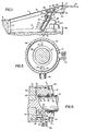
- Fig. 1 shows a dockboard 1 which is mounted within a pit 2 or depression in a loading dock 3.
- the dockboard is adapted to bridge the gap between the loading dock and the bed of a truck or carrier which is located in front of the dockboard.
- the dockboard 1 includes a supporting structure or frame 4, and the rear end of a ramp or deck plate 5 is pivoted to the supporting structure, so that the ramp is movable from a generally horizontal cross traffic position, where the ramp is generally flush with the upper surface of the dock 3, to an upwardly inclined position, as shown in Fig. 2.
- Hinged to the forward edge of the ramp 5 is a lip 6 which is movable between a downwardly hanging, pendant position and an outwardly extended position, as shown in Fig. 2, where the lip forms an extension to the ramp.
- the lip 6 is hinged to the ramp 5 by a' series of lugs 7 which are connected to the underside of the lip and are mounted for rotation on a hinge pin 8 which is connected to the forward end of the ramp.
- the construction of the frame, ramp and lip is conventional and is of a type such as shown in United States Patent No. 4,068,338.
- a main lift cylinder 9 interconnects the supporting structure 4 and the ramp 5 serves to pivot the ramp from the horizontal cross traffic position to the upwardly inclined position, while a second lip lifting cylinder 20 intercon-. nects the ramp and the lip and acts to move the lip to the extended position.
- the main lift cylinder unit 9 comprises a cylinder 11 having a tubular sleeve 12 at its lower end which is pivoted to lugs 13 on the supporting structure 4 through a pin 14.
- the cylinder 11 is composed of a generally cylindrical outer shell 15, the ends of which are enclosed by a lower head 16 and an upper head 17.
- a piston 18 is mounted for sliding movement within the shell 15 and carries a piston rod 19 that extends through head 17.
- Hydraulic fluid is supplied to the lower end of the cylinder 11 through fitting 20 and is supplied to the upper end of the cylinder through a fitting 21.
- a line 22 connects the fittings 20 and 21 and a velocity fuse 23 is located in line 22.
- the velocity fuse 23 is of conventional construction and serves to prevent rapid descent of the ramp 5 in the event a truck pulls away from the loading dock when an added load, such as a fork lift truck, is on the ramp.
- Line 24 connects the line 22 with..a reservoir 25 for hydraulic fluid which is mounted on the supporting structure 4 and an orifice 26 of conventional construction is located in line 26.
- the orifice 26 provides free flow of hydraulic fluid from the reservoir 25 through the line 24 but provides a restriction to flow in the opposite direction.
- a conventional motor pump unit 27 is mounted adjacent the reservoir 25 and when operated, serves to deliver hydraulic fluid from the reservoir through line 24 and line 22 to the fittings 20 and 21 of the cylinder.
- the upper end of the piston rod carries sleeve 28 which is connected to lug 29 located on the underside of the ramp 5 by a pin 30.
- the construction of the upper head 17 is best illustrated in Fig. 3.
- the head is retained within the shell 15 of the cylinder by a pair of retaining rings 31 and 32.
- Ring 31 is engaged within a groove in the inner surface of shell 15 and prevents outward movement of the head from the shell, while retaining ring 32 is engaged within a groove in the head and through engagement with ring 31 prevents inward axial movement of the head relative to shell 17.
- the head 17 is sealed to the rod 19 by a pair of o-rings 33 and 34 and a lip seal 35.
- the head 17 is sealed to the shell by 0-rings 36 and 37.
- a fitting 38 is connected to the cylinder 11 and communicates with a radial passage 39 in head 17.
- the ends of the radial passage 39 communicate with an inner annular passage 40 and an outer annular passage 41.
- Extending longitudinally between the radial passage 39 and the inner face of the head 17 is a longitudinal passage 42 and a conventional cartridge type check valve 43 is mounted within the passage 42.
- the check valve 43 permits free flow of fluid in a direction from the passage 39 to the interior of the cylinder 11, but prevents flow of fluid in the opposite direction.
- the inner face of head 17 is provided with a radial groove 44 which communicates with an inner annular recess 45 and outer annular recess 46.
- a slot 47 formed in the rod 19 adjacent the piston 18 will move into alignment with the upper head 17, as illustrated in Fig, 6, and will establish communication between the annular passage 45 and the radial passage 39 and fitting 38, so that the hydraulic fluid can then flow from the interior of the cylinder 11 through line 48, which is connected to fitting 38, to the lip lifting cylinder 10 to extend the lip 6.
- one end of cylinder 10 is pivotally connected to lugs 49 which extend downwardly from the undersurface of the ramp and a piston rod or ram 50 is slidably mounted within the cylinder and is pivotally connected to a lip lug 51 which is mounted on the lower surface of the lip.
- a piston rod or ram 50 is slidably mounted within the cylinder and is pivotally connected to a lip lug 51 which is mounted on the lower surface of the lip.
- the ramp 5 will normally be stored in the horizontal cross traffic position. After a truck has pulled into position in front of the dock 3 for loading, the operator will push the "UP" button on the control panel which operates the motor pump unit 27 to supply pressurized hydraulic fluid from the reservoir 25 through lines 24 and 22 to both ends of the cylinder 11. Due to the difference in force applied to opposite faces of piston 18, as previously described, the piston 18 will be moved upwardly in the cylinder 11 to extend the piston rod 19, causing the ramp 5 to move to the upwardly inclined position. As the piston moves upwardly, the fluid in the portion of the cylinder above the piston will be displaced through line 22 to the lower portion of the cylinder, beneath the piston.
- the slot 46 in the rod 19 will establish communication between the interior of the cylinder and the radial passage 39, thereby permitting hydraulic fluid to flow from the main cylinder 11 through line 48 to the lip lifting cylinder unit 10, to extend rod 50 and pivot the lip to the extended position.
- the lip lifting action will occur when the ramp is about 1 inch from its uppermost position.
- the added volume of fluid to be supplied to the lip lifting cylinder will be delivered from the reservoir 25 through fitting 21 to the main cylinder 9 and then to the lip lifting cylinder.
- the operator With the ramp fully elevated, the operator will then disengage the "UP" button on the control panel, discontinuing the flow of pressurized fluid to the main lift cylinder unit. Due to the combined weight of the ramp and the lip, the ramp will descend by gravity and the hydraulic fluid located within the cylinder 11 beneath the piston 18 will flow through the line 22 to the upper end of the cylinder, as the piston 18 descends within the cylinder 11. Because the effective area of the cylinder beneath the piston is greater than that above the piston, a portion of the displaced fluid from the lower end of the cylinder will be returned to the reservoir 25 through line 14. In passing through the orifice 26 a back pressure is generated which is sufficient to prevent the lip lifting cylinder unit 10 from retracting. Thus, as the ramp descends, the lip will be retained in the extended position.
- both the ramp and the lip are then supported by the trailer bed and the pressure in both the main cylinder unit 9 and the lip lifting cylinder 10 will drop to near ambient pressure.
- the invention provides a hydraulically operated dockboard construction in which the valving for supply-' ing hydraulic fluid to the lip lifting cylinder is an integral part of the main lift cylinder. This arrangement simplifies the overall construction resulting in reduced cost and greater efficiency.
Landscapes
- Engineering & Computer Science (AREA)
- Mechanical Engineering (AREA)
- Actuator (AREA)
- Forklifts And Lifting Vehicles (AREA)
Applications Claiming Priority (2)
| Application Number | Priority Date | Filing Date | Title |
|---|---|---|---|
| US06/175,143 US4365374A (en) | 1980-08-04 | 1980-08-04 | Hydraulically operated dockboard |
| US175143 | 1980-08-04 |
Publications (2)
| Publication Number | Publication Date |
|---|---|
| EP0045581A1 true EP0045581A1 (de) | 1982-02-10 |
| EP0045581B1 EP0045581B1 (de) | 1984-04-04 |
Family
ID=22639092
Family Applications (1)
| Application Number | Title | Priority Date | Filing Date |
|---|---|---|---|
| EP81303217A Expired EP0045581B1 (de) | 1980-08-04 | 1981-07-14 | Hydraulische Steuerung für eine Verladerampe |
Country Status (4)
| Country | Link |
|---|---|
| US (1) | US4365374A (de) |
| EP (1) | EP0045581B1 (de) |
| CA (1) | CA1154915A (de) |
| DE (1) | DE3162964D1 (de) |
Cited By (6)
| Publication number | Priority date | Publication date | Assignee | Title |
|---|---|---|---|---|
| EP0117394A1 (de) * | 1983-02-01 | 1984-09-05 | Kurt Alten | Überfahrbrücke für Rampen |
| EP0440349A1 (de) * | 1990-01-16 | 1991-08-07 | Kelley Company Inc. | Hydraulisch betätigte Laderampe |
| EP0655486A2 (de) | 1993-11-25 | 1995-05-31 | BASF Aktiengesellschaft | Magnetisierbare Glanzpigmente |
| FR2786755A1 (fr) | 1998-12-02 | 2000-06-09 | Hymeca Manutention | Procede et dispositif d'assistance a l'equilibrage d'un niveleur de quai |
| CN106144680A (zh) * | 2015-03-30 | 2016-11-23 | 天津市冰科制冷设备有限公司 | 一种装卸平台 |
| CN106144681A (zh) * | 2015-03-30 | 2016-11-23 | 天津市冰科制冷设备有限公司 | 一种冷库月台用液压升降装车平台 |
Families Citing this family (32)
| Publication number | Priority date | Publication date | Assignee | Title |
|---|---|---|---|---|
| US4593424A (en) * | 1983-12-30 | 1986-06-10 | Beck Earl A | Hydraulic ramp/dock/loader apparatus |
| US4641388A (en) * | 1984-08-01 | 1987-02-10 | Kelley Company, Inc. | Hydraulic control system for a dockboard |
| US4744121A (en) * | 1987-02-20 | 1988-05-17 | Rite-Hite Corporation | Loading dock and hydraulic system therefor |
| NO161747C (no) * | 1987-03-30 | 1989-09-20 | Tore Ivarsson | Landingsbrygge. |
| US4823421A (en) * | 1987-07-01 | 1989-04-25 | Eriks Holding N.V. | Hydraulic lip actuator for dock leveler |
| US4944062A (en) * | 1987-12-15 | 1990-07-31 | Dock Leveler Manufacturing, Inc. | Dock leveler control system |
| US4827549A (en) * | 1987-12-30 | 1989-05-09 | Dock Leveler Manufacturing, Inc. | Hydraulic dock leveler |
| US5117526A (en) * | 1990-05-03 | 1992-06-02 | The Serco Corporation | Vertically storing dock leveler |
| US5205123A (en) * | 1990-09-06 | 1993-04-27 | Dunstan Phillip E | Infinitely variable differential hydrostatic transmission |
| US5205010A (en) * | 1991-08-13 | 1993-04-27 | Kelley Company Inc. | Return-to-dock level mechanism for a hydraulic dockboard |
| US5274867A (en) * | 1991-12-26 | 1994-01-04 | Kelley Company Inc. | Hydraulically operated edge-of-dock leveler |
| DE4223383A1 (de) * | 1992-07-16 | 1994-01-20 | Basf Ag | Glanzpigmente mit metallsulfidhaltiger Beschichtung |
| CA2131650C (en) * | 1994-09-08 | 2000-05-23 | Jean-Francois Hotte | System for removably installing equipments on the frame of a truck |
| US5526545A (en) * | 1995-01-11 | 1996-06-18 | The Serco Corporation | Automatic return to dock mechanism |
| US5784740A (en) * | 1996-09-17 | 1998-07-28 | Overhead Door Corporation | Dock leveler |
| CA2334691C (en) | 1998-06-09 | 2006-12-05 | Rite-Hite Holding Corporation | Recycle control system for dock levelers |
| US6065172A (en) * | 1998-06-09 | 2000-05-23 | Rite-Hite Holding Corporation | Hydraulic control circuit |
| US6643880B1 (en) | 1999-11-01 | 2003-11-11 | Kelley Company, Inc. | Dock leveler |
| US6880301B2 (en) * | 2001-03-06 | 2005-04-19 | Rite-Hite Holding Corporation | Pivotal and translational dock leveler lip |
| US6698052B2 (en) | 2002-06-06 | 2004-03-02 | Renum Hydraulics Ltd. | Hydraulically assisted restraint device |
| US7213285B2 (en) * | 2004-08-12 | 2007-05-08 | Rite-Hite Holding Corporation | Pivotal and vertically translatable dock leveler lip |
| US20060123569A1 (en) * | 2004-12-14 | 2006-06-15 | Rite-Hite Holding Corporation | Dock leveler lip providing multi-position barrier |
| DE102005052116B4 (de) * | 2005-11-02 | 2017-10-26 | Linde Material Handling Gmbh | Einrichtung zur Sicherung der Bewegungsreihenfolge von mindestens zwei fluidbetätigten Verdrängereinheiten |
| US7162762B1 (en) | 2006-06-02 | 2007-01-16 | Nordock, Inc. | Dock leveler with inflatable bag |
| US8091942B2 (en) * | 2008-11-19 | 2012-01-10 | Gumbo Product Development, Inc. | Recreational vehicle with ramp door |
| US8065770B2 (en) * | 2009-04-22 | 2011-11-29 | Rite-Hite Holding Corporation | Dock leveler with continuous position sensing |
| US20110047723A1 (en) * | 2009-09-01 | 2011-03-03 | Lockheed Martin Corporation | Closed-loop control system for controlling a device |
| US8020234B2 (en) * | 2009-10-16 | 2011-09-20 | Lift-U, A Division Of Hogan Mfg., Inc. | Counterbalance mechanism for fold out ramp |
| US7913343B1 (en) | 2009-10-16 | 2011-03-29 | Lift-U, A Division Of Hogan Mfg., Inc. | Counterbalance mechanism for fold out ramp |
| US7913342B1 (en) | 2009-10-16 | 2011-03-29 | Lift-U, A Division Of Hogan Mfg., Inc. | Counterbalance mechanism for fold out ramp |
| US7913341B1 (en) | 2009-10-16 | 2011-03-29 | Lift-U, A Division Of Hogan Mfg., Inc. | Counterbalance mechanism for fold out ramp |
| CN102530586A (zh) * | 2012-01-18 | 2012-07-04 | 济南华北升降平台制造有限公司 | 固定式登车桥 |
Citations (4)
| Publication number | Priority date | Publication date | Assignee | Title |
|---|---|---|---|---|
| FR1347424A (fr) * | 1963-01-31 | 1963-12-27 | Plessey Co Ltd | Système d'actionnement hydraulique ou pneumatique |
| US3388413A (en) * | 1966-04-11 | 1968-06-18 | Autoquip Corp | Hydraulic dock ramp controls |
| GB1294318A (en) * | 1969-07-04 | 1972-10-25 | Dermont Franklin Loblick | Dockboard installations |
| DE2815535A1 (de) * | 1978-04-11 | 1979-10-25 | Richard Schminke | Laderampe |
Family Cites Families (12)
| Publication number | Priority date | Publication date | Assignee | Title |
|---|---|---|---|---|
| CA717691A (en) * | 1965-09-14 | P. Dieter Donald | Dockboard | |
| US2644971A (en) * | 1949-11-18 | 1953-07-14 | Arthur E Rowe | Loading dock construction |
| GB723723A (en) * | 1952-11-22 | 1955-02-09 | Telehoist Ltd | Vehicle ramps |
| US2881457A (en) * | 1953-08-11 | 1959-04-14 | Dover Corp | Loading dock ramp |
| US2997988A (en) * | 1959-08-03 | 1961-08-29 | Young Spring & Wire Corp | Fluid motor mechanism |
| US3201814A (en) * | 1963-08-05 | 1965-08-24 | T & S Equipment Co | Hydraulically actuated dock board with hinged lip |
| US3290709A (en) * | 1964-11-17 | 1966-12-13 | Symington Wayne Corp | Automatic lip for power operated loading platform |
| US3290710A (en) * | 1964-11-17 | 1966-12-13 | Symington Wayne Corp | Lip-operated switching device for power operated loading platform |
| US3345665A (en) * | 1965-09-29 | 1967-10-10 | Symington Wayne Corp | Fluid-operated ramp having automatic lip |
| US4068338A (en) * | 1976-10-01 | 1978-01-17 | Kelley Company, Inc. | Ramp construction for a dockboard |
| US4081874A (en) * | 1977-01-12 | 1978-04-04 | Kelley Company, Inc. | Hydraulic dockboard system |
| US4110860A (en) * | 1977-07-26 | 1978-09-05 | Rite-Hite Corporation | Leveler assembly for a loading dock |
-
1980
- 1980-08-04 US US06/175,143 patent/US4365374A/en not_active Expired - Lifetime
-
1981
- 1981-07-14 DE DE8181303217T patent/DE3162964D1/de not_active Expired
- 1981-07-14 EP EP81303217A patent/EP0045581B1/de not_active Expired
- 1981-07-16 CA CA000381859A patent/CA1154915A/en not_active Expired
Patent Citations (4)
| Publication number | Priority date | Publication date | Assignee | Title |
|---|---|---|---|---|
| FR1347424A (fr) * | 1963-01-31 | 1963-12-27 | Plessey Co Ltd | Système d'actionnement hydraulique ou pneumatique |
| US3388413A (en) * | 1966-04-11 | 1968-06-18 | Autoquip Corp | Hydraulic dock ramp controls |
| GB1294318A (en) * | 1969-07-04 | 1972-10-25 | Dermont Franklin Loblick | Dockboard installations |
| DE2815535A1 (de) * | 1978-04-11 | 1979-10-25 | Richard Schminke | Laderampe |
Cited By (6)
| Publication number | Priority date | Publication date | Assignee | Title |
|---|---|---|---|---|
| EP0117394A1 (de) * | 1983-02-01 | 1984-09-05 | Kurt Alten | Überfahrbrücke für Rampen |
| EP0440349A1 (de) * | 1990-01-16 | 1991-08-07 | Kelley Company Inc. | Hydraulisch betätigte Laderampe |
| EP0655486A2 (de) | 1993-11-25 | 1995-05-31 | BASF Aktiengesellschaft | Magnetisierbare Glanzpigmente |
| FR2786755A1 (fr) | 1998-12-02 | 2000-06-09 | Hymeca Manutention | Procede et dispositif d'assistance a l'equilibrage d'un niveleur de quai |
| CN106144680A (zh) * | 2015-03-30 | 2016-11-23 | 天津市冰科制冷设备有限公司 | 一种装卸平台 |
| CN106144681A (zh) * | 2015-03-30 | 2016-11-23 | 天津市冰科制冷设备有限公司 | 一种冷库月台用液压升降装车平台 |
Also Published As
| Publication number | Publication date |
|---|---|
| EP0045581B1 (de) | 1984-04-04 |
| DE3162964D1 (en) | 1984-05-10 |
| CA1154915A (en) | 1983-10-11 |
| US4365374A (en) | 1982-12-28 |
Similar Documents
| Publication | Publication Date | Title |
|---|---|---|
| US4365374A (en) | Hydraulically operated dockboard | |
| US4641388A (en) | Hydraulic control system for a dockboard | |
| EP0440349A1 (de) | Hydraulisch betätigte Laderampe | |
| US4091488A (en) | Dockboard utilizing a gas spring for counterbalancing | |
| US2644971A (en) | Loading dock construction | |
| US4969792A (en) | Truck supporting device | |
| US3835497A (en) | Dockboard safety stop | |
| EP1020376A2 (de) | Müllsammelfahrzeug | |
| US5205010A (en) | Return-to-dock level mechanism for a hydraulic dockboard | |
| US4619008A (en) | Dockboard construction | |
| US3388413A (en) | Hydraulic dock ramp controls | |
| JPH07502314A (ja) | 膨張可能なバッグを有するドックレベラー | |
| US2475443A (en) | Semitrailer with body elevating and lowering means | |
| EP0721423B1 (de) | Stütz- und befestigungsvorrichtung für einen hebesack einer ladeplattform | |
| US2989196A (en) | Hydraulic hoist for vehicles | |
| US3235895A (en) | Extendable power-operated ramp | |
| US6192804B1 (en) | Hydraulically actuated railway car dumping system | |
| US1638009A (en) | Tipping wagon and the like | |
| US3656199A (en) | Safety mechanism for a hydraulically operated dockboard | |
| US3977544A (en) | Entirely hydraulic loading platform for trucks | |
| US2749175A (en) | Latch control for dump trucks | |
| US5176226A (en) | Tailgate closing mechanism for tailgate hoist | |
| US5299856A (en) | Dump vehicle with hydraulic lock for material holding container | |
| US5274867A (en) | Hydraulically operated edge-of-dock leveler | |
| CA1308222C (en) | Truck supporting device |
Legal Events
| Date | Code | Title | Description |
|---|---|---|---|
| PUAI | Public reference made under article 153(3) epc to a published international application that has entered the european phase |
Free format text: ORIGINAL CODE: 0009012 |
|
| AK | Designated contracting states |
Designated state(s): DE FR GB IT NL SE |
|
| 17P | Request for examination filed |
Effective date: 19820602 |
|
| GRAA | (expected) grant |
Free format text: ORIGINAL CODE: 0009210 |
|
| AK | Designated contracting states |
Designated state(s): DE FR GB IT NL SE |
|
| PG25 | Lapsed in a contracting state [announced via postgrant information from national office to epo] |
Ref country code: SE Effective date: 19840404 Ref country code: IT Free format text: LAPSE BECAUSE OF FAILURE TO SUBMIT A TRANSLATION OF THE DESCRIPTION OR TO PAY THE FEE WITHIN THE PRESCRIBED TIME-LIMIT;WARNING: LAPSES OF ITALIAN PATENTS WITH EFFECTIVE DATE BEFORE 2007 MAY HAVE OCCURRED AT ANY TIME BEFORE 2007. THE CORRECT EFFECTIVE DATE MAY BE DIFFERENT FROM THE ONE RECORDED. Effective date: 19840404 |
|
| REF | Corresponds to: |
Ref document number: 3162964 Country of ref document: DE Date of ref document: 19840510 |
|
| ET | Fr: translation filed | ||
| PLBE | No opposition filed within time limit |
Free format text: ORIGINAL CODE: 0009261 |
|
| STAA | Information on the status of an ep patent application or granted ep patent |
Free format text: STATUS: NO OPPOSITION FILED WITHIN TIME LIMIT |
|
| 26N | No opposition filed | ||
| PGFP | Annual fee paid to national office [announced via postgrant information from national office to epo] |
Ref country code: FR Payment date: 19980611 Year of fee payment: 18 |
|
| PGFP | Annual fee paid to national office [announced via postgrant information from national office to epo] |
Ref country code: GB Payment date: 19980623 Year of fee payment: 18 |
|
| PG25 | Lapsed in a contracting state [announced via postgrant information from national office to epo] |
Ref country code: GB Free format text: LAPSE BECAUSE OF NON-PAYMENT OF DUE FEES Effective date: 19990714 |
|
| PG25 | Lapsed in a contracting state [announced via postgrant information from national office to epo] |
Ref country code: FR Free format text: THE PATENT HAS BEEN ANNULLED BY A DECISION OF A NATIONAL AUTHORITY Effective date: 19990731 |
|
| GBPC | Gb: european patent ceased through non-payment of renewal fee |
Effective date: 19990714 |
|
| REG | Reference to a national code |
Ref country code: FR Ref legal event code: ST |
|
| PGFP | Annual fee paid to national office [announced via postgrant information from national office to epo] |
Ref country code: DE Payment date: 20000724 Year of fee payment: 20 |
|
| PGFP | Annual fee paid to national office [announced via postgrant information from national office to epo] |
Ref country code: NL Payment date: 20000725 Year of fee payment: 20 |
|
| PG25 | Lapsed in a contracting state [announced via postgrant information from national office to epo] |
Ref country code: NL Free format text: LAPSE BECAUSE OF EXPIRATION OF PROTECTION Effective date: 20010714 |
|
| NLV7 | Nl: ceased due to reaching the maximum lifetime of a patent |
Effective date: 20010714 |