EP0044206A2 - Schweissverfahren und -vorrichtung - Google Patents
Schweissverfahren und -vorrichtung Download PDFInfo
- Publication number
- EP0044206A2 EP0044206A2 EP81303168A EP81303168A EP0044206A2 EP 0044206 A2 EP0044206 A2 EP 0044206A2 EP 81303168 A EP81303168 A EP 81303168A EP 81303168 A EP81303168 A EP 81303168A EP 0044206 A2 EP0044206 A2 EP 0044206A2
- Authority
- EP
- European Patent Office
- Prior art keywords
- materials
- porous
- sealing
- fluid
- films
- Prior art date
- Legal status (The legal status is an assumption and is not a legal conclusion. Google has not performed a legal analysis and makes no representation as to the accuracy of the status listed.)
- Withdrawn
Links
Images


Classifications
-
- B—PERFORMING OPERATIONS; TRANSPORTING
- B29—WORKING OF PLASTICS; WORKING OF SUBSTANCES IN A PLASTIC STATE IN GENERAL
- B29C—SHAPING OR JOINING OF PLASTICS; SHAPING OF MATERIAL IN A PLASTIC STATE, NOT OTHERWISE PROVIDED FOR; AFTER-TREATMENT OF THE SHAPED PRODUCTS, e.g. REPAIRING
- B29C65/00—Joining or sealing of preformed parts, e.g. welding of plastics materials; Apparatus therefor
- B29C65/02—Joining or sealing of preformed parts, e.g. welding of plastics materials; Apparatus therefor by heating, with or without pressure
- B29C65/10—Joining or sealing of preformed parts, e.g. welding of plastics materials; Apparatus therefor by heating, with or without pressure using hot gases (e.g. combustion gases) or flames coming in contact with at least one of the parts to be joined
-
- B—PERFORMING OPERATIONS; TRANSPORTING
- B29—WORKING OF PLASTICS; WORKING OF SUBSTANCES IN A PLASTIC STATE IN GENERAL
- B29C—SHAPING OR JOINING OF PLASTICS; SHAPING OF MATERIAL IN A PLASTIC STATE, NOT OTHERWISE PROVIDED FOR; AFTER-TREATMENT OF THE SHAPED PRODUCTS, e.g. REPAIRING
- B29C66/00—General aspects of processes or apparatus for joining preformed parts
- B29C66/003—Protecting areas of the parts to be joined from overheating
-
- B—PERFORMING OPERATIONS; TRANSPORTING
- B29—WORKING OF PLASTICS; WORKING OF SUBSTANCES IN A PLASTIC STATE IN GENERAL
- B29C—SHAPING OR JOINING OF PLASTICS; SHAPING OF MATERIAL IN A PLASTIC STATE, NOT OTHERWISE PROVIDED FOR; AFTER-TREATMENT OF THE SHAPED PRODUCTS, e.g. REPAIRING
- B29C66/00—General aspects of processes or apparatus for joining preformed parts
- B29C66/70—General aspects of processes or apparatus for joining preformed parts characterised by the composition, physical properties or the structure of the material of the parts to be joined; Joining with non-plastics material
- B29C66/73—General aspects of processes or apparatus for joining preformed parts characterised by the composition, physical properties or the structure of the material of the parts to be joined; Joining with non-plastics material characterised by the intensive physical properties of the material of the parts to be joined, by the optical properties of the material of the parts to be joined, by the extensive physical properties of the parts to be joined, by the state of the material of the parts to be joined or by the material of the parts to be joined being a thermoplastic or a thermoset
- B29C66/739—General aspects of processes or apparatus for joining preformed parts characterised by the composition, physical properties or the structure of the material of the parts to be joined; Joining with non-plastics material characterised by the intensive physical properties of the material of the parts to be joined, by the optical properties of the material of the parts to be joined, by the extensive physical properties of the parts to be joined, by the state of the material of the parts to be joined or by the material of the parts to be joined being a thermoplastic or a thermoset characterised by the material of the parts to be joined being a thermoplastic or a thermoset
- B29C66/7392—General aspects of processes or apparatus for joining preformed parts characterised by the composition, physical properties or the structure of the material of the parts to be joined; Joining with non-plastics material characterised by the intensive physical properties of the material of the parts to be joined, by the optical properties of the material of the parts to be joined, by the extensive physical properties of the parts to be joined, by the state of the material of the parts to be joined or by the material of the parts to be joined being a thermoplastic or a thermoset characterised by the material of the parts to be joined being a thermoplastic or a thermoset characterised by the material of at least one of the parts being a thermoplastic
- B29C66/73921—General aspects of processes or apparatus for joining preformed parts characterised by the composition, physical properties or the structure of the material of the parts to be joined; Joining with non-plastics material characterised by the intensive physical properties of the material of the parts to be joined, by the optical properties of the material of the parts to be joined, by the extensive physical properties of the parts to be joined, by the state of the material of the parts to be joined or by the material of the parts to be joined being a thermoplastic or a thermoset characterised by the material of the parts to be joined being a thermoplastic or a thermoset characterised by the material of at least one of the parts being a thermoplastic characterised by the materials of both parts being thermoplastics
-
- B—PERFORMING OPERATIONS; TRANSPORTING
- B29—WORKING OF PLASTICS; WORKING OF SUBSTANCES IN A PLASTIC STATE IN GENERAL
- B29C—SHAPING OR JOINING OF PLASTICS; SHAPING OF MATERIAL IN A PLASTIC STATE, NOT OTHERWISE PROVIDED FOR; AFTER-TREATMENT OF THE SHAPED PRODUCTS, e.g. REPAIRING
- B29C66/00—General aspects of processes or apparatus for joining preformed parts
- B29C66/80—General aspects of machine operations or constructions and parts thereof
- B29C66/81—General aspects of the pressing elements, i.e. the elements applying pressure on the parts to be joined in the area to be joined, e.g. the welding jaws or clamps
- B29C66/812—General aspects of the pressing elements, i.e. the elements applying pressure on the parts to be joined in the area to be joined, e.g. the welding jaws or clamps characterised by the composition, by the structure, by the intensive physical properties or by the optical properties of the material constituting the pressing elements, e.g. constituting the welding jaws or clamps
- B29C66/8124—General aspects of the pressing elements, i.e. the elements applying pressure on the parts to be joined in the area to be joined, e.g. the welding jaws or clamps characterised by the composition, by the structure, by the intensive physical properties or by the optical properties of the material constituting the pressing elements, e.g. constituting the welding jaws or clamps characterised by the structure of the material constituting the pressing elements, e.g. constituting the welding jaws or clamps
- B29C66/81241—General aspects of the pressing elements, i.e. the elements applying pressure on the parts to be joined in the area to be joined, e.g. the welding jaws or clamps characterised by the composition, by the structure, by the intensive physical properties or by the optical properties of the material constituting the pressing elements, e.g. constituting the welding jaws or clamps characterised by the structure of the material constituting the pressing elements, e.g. constituting the welding jaws or clamps being porous or sintered
-
- B—PERFORMING OPERATIONS; TRANSPORTING
- B29—WORKING OF PLASTICS; WORKING OF SUBSTANCES IN A PLASTIC STATE IN GENERAL
- B29C—SHAPING OR JOINING OF PLASTICS; SHAPING OF MATERIAL IN A PLASTIC STATE, NOT OTHERWISE PROVIDED FOR; AFTER-TREATMENT OF THE SHAPED PRODUCTS, e.g. REPAIRING
- B29C66/00—General aspects of processes or apparatus for joining preformed parts
- B29C66/80—General aspects of machine operations or constructions and parts thereof
- B29C66/82—Pressure application arrangements, e.g. transmission or actuating mechanisms for joining tools or clamps
- B29C66/824—Actuating mechanisms
- B29C66/8242—Pneumatic or hydraulic drives
-
- B—PERFORMING OPERATIONS; TRANSPORTING
- B29—WORKING OF PLASTICS; WORKING OF SUBSTANCES IN A PLASTIC STATE IN GENERAL
- B29C—SHAPING OR JOINING OF PLASTICS; SHAPING OF MATERIAL IN A PLASTIC STATE, NOT OTHERWISE PROVIDED FOR; AFTER-TREATMENT OF THE SHAPED PRODUCTS, e.g. REPAIRING
- B29C66/00—General aspects of processes or apparatus for joining preformed parts
- B29C66/80—General aspects of machine operations or constructions and parts thereof
- B29C66/82—Pressure application arrangements, e.g. transmission or actuating mechanisms for joining tools or clamps
- B29C66/826—Pressure application arrangements, e.g. transmission or actuating mechanisms for joining tools or clamps without using a separate pressure application tool, e.g. the own weight of the parts to be joined
- B29C66/8266—Pressure application arrangements, e.g. transmission or actuating mechanisms for joining tools or clamps without using a separate pressure application tool, e.g. the own weight of the parts to be joined using fluid pressure directly acting on the parts to be joined
-
- B—PERFORMING OPERATIONS; TRANSPORTING
- B29—WORKING OF PLASTICS; WORKING OF SUBSTANCES IN A PLASTIC STATE IN GENERAL
- B29C—SHAPING OR JOINING OF PLASTICS; SHAPING OF MATERIAL IN A PLASTIC STATE, NOT OTHERWISE PROVIDED FOR; AFTER-TREATMENT OF THE SHAPED PRODUCTS, e.g. REPAIRING
- B29C66/00—General aspects of processes or apparatus for joining preformed parts
- B29C66/80—General aspects of machine operations or constructions and parts thereof
- B29C66/83—General aspects of machine operations or constructions and parts thereof characterised by the movement of the joining or pressing tools
- B29C66/832—Reciprocating joining or pressing tools
- B29C66/8322—Joining or pressing tools reciprocating along one axis
-
- B—PERFORMING OPERATIONS; TRANSPORTING
- B29—WORKING OF PLASTICS; WORKING OF SUBSTANCES IN A PLASTIC STATE IN GENERAL
- B29C—SHAPING OR JOINING OF PLASTICS; SHAPING OF MATERIAL IN A PLASTIC STATE, NOT OTHERWISE PROVIDED FOR; AFTER-TREATMENT OF THE SHAPED PRODUCTS, e.g. REPAIRING
- B29C66/00—General aspects of processes or apparatus for joining preformed parts
- B29C66/01—General aspects dealing with the joint area or with the area to be joined
- B29C66/05—Particular design of joint configurations
- B29C66/10—Particular design of joint configurations particular design of the joint cross-sections
- B29C66/11—Joint cross-sections comprising a single joint-segment, i.e. one of the parts to be joined comprising a single joint-segment in the joint cross-section
- B29C66/112—Single lapped joints
- B29C66/1122—Single lap to lap joints, i.e. overlap joints
-
- B—PERFORMING OPERATIONS; TRANSPORTING
- B29—WORKING OF PLASTICS; WORKING OF SUBSTANCES IN A PLASTIC STATE IN GENERAL
- B29C—SHAPING OR JOINING OF PLASTICS; SHAPING OF MATERIAL IN A PLASTIC STATE, NOT OTHERWISE PROVIDED FOR; AFTER-TREATMENT OF THE SHAPED PRODUCTS, e.g. REPAIRING
- B29C66/00—General aspects of processes or apparatus for joining preformed parts
- B29C66/40—General aspects of joining substantially flat articles, e.g. plates, sheets or web-like materials; Making flat seams in tubular or hollow articles; Joining single elements to substantially flat surfaces
- B29C66/41—Joining substantially flat articles ; Making flat seams in tubular or hollow articles
- B29C66/43—Joining a relatively small portion of the surface of said articles
-
- B—PERFORMING OPERATIONS; TRANSPORTING
- B29—WORKING OF PLASTICS; WORKING OF SUBSTANCES IN A PLASTIC STATE IN GENERAL
- B29C—SHAPING OR JOINING OF PLASTICS; SHAPING OF MATERIAL IN A PLASTIC STATE, NOT OTHERWISE PROVIDED FOR; AFTER-TREATMENT OF THE SHAPED PRODUCTS, e.g. REPAIRING
- B29C66/00—General aspects of processes or apparatus for joining preformed parts
- B29C66/70—General aspects of processes or apparatus for joining preformed parts characterised by the composition, physical properties or the structure of the material of the parts to be joined; Joining with non-plastics material
- B29C66/71—General aspects of processes or apparatus for joining preformed parts characterised by the composition, physical properties or the structure of the material of the parts to be joined; Joining with non-plastics material characterised by the composition of the plastics material of the parts to be joined
-
- B—PERFORMING OPERATIONS; TRANSPORTING
- B29—WORKING OF PLASTICS; WORKING OF SUBSTANCES IN A PLASTIC STATE IN GENERAL
- B29C—SHAPING OR JOINING OF PLASTICS; SHAPING OF MATERIAL IN A PLASTIC STATE, NOT OTHERWISE PROVIDED FOR; AFTER-TREATMENT OF THE SHAPED PRODUCTS, e.g. REPAIRING
- B29C66/00—General aspects of processes or apparatus for joining preformed parts
- B29C66/70—General aspects of processes or apparatus for joining preformed parts characterised by the composition, physical properties or the structure of the material of the parts to be joined; Joining with non-plastics material
- B29C66/72—General aspects of processes or apparatus for joining preformed parts characterised by the composition, physical properties or the structure of the material of the parts to be joined; Joining with non-plastics material characterised by the structure of the material of the parts to be joined
- B29C66/723—General aspects of processes or apparatus for joining preformed parts characterised by the composition, physical properties or the structure of the material of the parts to be joined; Joining with non-plastics material characterised by the structure of the material of the parts to be joined being multi-layered
- B29C66/7232—General aspects of processes or apparatus for joining preformed parts characterised by the composition, physical properties or the structure of the material of the parts to be joined; Joining with non-plastics material characterised by the structure of the material of the parts to be joined being multi-layered comprising a non-plastics layer
- B29C66/72327—General aspects of processes or apparatus for joining preformed parts characterised by the composition, physical properties or the structure of the material of the parts to be joined; Joining with non-plastics material characterised by the structure of the material of the parts to be joined being multi-layered comprising a non-plastics layer consisting of natural products or their composites, not provided for in B29C66/72321 - B29C66/72324
- B29C66/72328—Paper
-
- B—PERFORMING OPERATIONS; TRANSPORTING
- B29—WORKING OF PLASTICS; WORKING OF SUBSTANCES IN A PLASTIC STATE IN GENERAL
- B29K—INDEXING SCHEME ASSOCIATED WITH SUBCLASSES B29B, B29C OR B29D, RELATING TO MOULDING MATERIALS OR TO MATERIALS FOR MOULDS, REINFORCEMENTS, FILLERS OR PREFORMED PARTS, e.g. INSERTS
- B29K2995/00—Properties of moulding materials, reinforcements, fillers, preformed parts or moulds
- B29K2995/0037—Other properties
- B29K2995/0065—Permeability to gases
Definitions
- This invention relates to the heat sealing of materials and, more particularly,to the heat sealing of materials by means other than directly contacting them with heating elements.
- thermoplastic films have been sealed together by compressing them between heated bars for a predetermined time and then releasing them.
- This operation has several well-known and significant difficulties, including fouling of the bars or release coverings used on them, burning of the materials, and the inability to quickly change the heating bar temperatures, such as for cooling the bars to accommodate intermittent interruptions in the sealing operation without burning the materials, or such as for heating the bars to quickly restart a sealing operation.
- Fanuzzi and Lepisto both describe the use of porous members disposed on each side of the materials to be sealed and the blowing of hot air through these members to impact on the materials, to heat them, to press them together, and to support them away from the surfaces of the porous members.
- porous plates when used as described in these two patents, themselves produce a "jet impact" effect on the materials. While a jet impact effect produced by porous plates may not have all the disadvantages as the perforated plate compared in Fanuzzi, for example, it continues to produce significant disadvantages of its own. These include undesirable excesses of tension and stress in the molten seal area due to imbalance of the sealing films when subjected to the jet impact area.
- porous plates can be used in an entirely different fluid flow regime which has none of the disadvantages of the "jet impact” effect, and which provides significant advantages of control, seal quality, and speed of sealing operations, over the devices described in Fanuzzi and Lepisto.
- a second, important aspect of the invention is directed to an improved process and apparatus both for overcoming such difficulties and at the same time, providing substantially improved seals and sealing operations.
- a method of materials in accordance with the invention includes the steps of passing the materials through at least one fluid bearing sealing area, which area is defined in part by at least one porous member having a porous surface, transmitting heated fluid through the porous member at a temperature sufficient to raise the materials to a temperature at which they can be heat sealed together in a predetermined location, and maintaining a predetermined distance between the porous surface and the materials and a predetermined fluid flow rate through the porous member to generate a fluid bearing flow regime to support and compress the materials for heat sealing.
- the preferred embodiment utilizes a fluid bearing flow regime produced by fluid flowing through and from a porous element and providing a non-stagnant boundary layer of fluid moving, not perpendicularly, but parallel to the porous element and the material to be sealed.
- the invention enables control of the movement, forces and stresses in sealable materials during a heat sealing operation when the materials are supported by fluids.
- a zoned porous element operates in the air bearing flow regime just mentioned and produces both heated and relatively cooled fluid at the same time for both heating materials to seal them, and for cooling materials within the operative perimeter of the same porous element.
- the first is the distinction between the jet impact effect provided by perforated plates or tubes, nozzles, or other contrived plural air streams, and that jet impact effect provided by operation of the porous elements of the type described in detail in the aforementioned Fanuzzi and Lepisto patents. This first distinction is described in detail in the Fanuzzi patent.
- the film may be spaced at some selected distance from the surface, near enough that fluid exuding therefrom impacts on the film.
- the distances through which this action takes place will be referred to as the jet impact region.
- the film crosses a transition distance or point where the capacity of the porous element and exuding fluid to support the film increases from a negative to a positive value. From this transition point down to a nearly zero distance between the surface and the film, the porous element and the exuding fluid operate in what is referred to as the true air bearing or fluid bearing region.
- the stiffness of the bearing i.e. its capacity to support the film and any back-up load thereon, increases as the film moves closer to the surface in the fluid bearing region.
- a stagnant boundary layer of fluid is region, a stagnant boundary layer of fluid is formed at the film surface and is supported by the perpendicular impact of fluid exuding from the porous element.
- This stagnant boundary layer does not tend to flow across the film surface, and substantially diminishes the capacity of the exuding fluid to transfer heat to the film for sealing.
- the stagnant boundary layer tends to insulate the film surface from the hottest fluid just exuding from the porous element.
- the flow of fluid from the surface of the porous element may be constant and uniform, however, it is primarily at a direction perpendicular to the film surface and, in creating the stagnant boundary layer of fluid at the film's surface, diminishes the transfer of heat to the film.
- porous element for sealing films when using a porous element for sealing films, in a jet impact flow regime, it is necessary to provide the necessary dwell time of the film in the porous element area be lengthening the porous elements, or by decreasing the film speed in that area, or both. This is necessary to ensure that sufficient quantities of heat will be transferred to the film for sealing, but it constitutes a disadvantage in that it limits the speed of any sealing operation.
- longer porous elements or film speeds, or both increase the time when the moving film is molten for sealing. The longer the film must remain molten or softened, the more susceptible it is to wrinkling and distortion. This increases the need to hold the film steady, and makes distortionless, wrinkleless seals more difficult.
- the jet impact flow regime provides the effective pressure which each provides.
- pressure is one of the operative parameters, it being necessary to effectively press the films together, during heating, so they can be sealed together.
- the fluid bearing flow regime provides greater pressures than the jet impact flow regime.
- the fluid bearing flow regime operates effectively in a relatively stiff bearing range and exerts more pressure, uniformly, on the films than where the films are further spaced from the porous element in the jet impact region. Moreover, this greater pressure is provided without unduly stressing the softened or molten film seal area since the net horizontal forces acting on the film in the fluid bearing regime are zero, as will be discussed later.
- the dwell time of the fluid i.e., the time it takes to move from the porous surface to outside the bearing area or perimeter. It might be expected that such fluid with such short dwell times would function to carry away most of its heat, rather than imparting it to the film, thus requiring additional film dwell time in the hot bearing area in order to provide a seal. In fact, this expected disadvantage has not occurred in the process of the invention for several reasons.
- the invention provides significantly increased heat transfer capacities and substantially shortens necessary molten film dwell time, which is beneficial to film handling and seal quality.
- One overall result then, from sealing in the true fluid bearing flow regime, is increased production of sealed materials.
- the increased heat transfer capacity permits a lesser temperature differential between the film sealing temperature and the porous element temperature. This facilitates intermittent operation making it easier to quickly heat or cool the porous element and the fluid exuding from it as will be appreciated.
- a fluid bearing flow regime which balances the film such that it floats in the bearing area, and does not tend to move out of the bearing area. This is accomplished in the fluid bearing flow regime by a boundary layer producing uniform pressure on the film but also a non-uniform lateral flow outward such that the net component of forces is essentially zero. Under these conditions in the fluid bearing flow regime, any horizontal forces tending to distort the molten film are minimized if not totally eliminated. As a result, film in the bearing area floats and is self-centering. In the jet impact regime, forces acting on the film do not net out to zero and the film tends to move out of the bearing area.
- porous element surfaces In order to obtain such a balanced floating action in the film in a fluid bearing regime, it is generally necessary to precisely construct the porous element surfaces and their disposition.
- opposed porous surfaces are disposed about .004" apart with no more than about + .0005" variation. Variations in parallelism much greater than this will unbalance the film and produce wrinkles or distortion in it.
- the film since the film will usually extend laterally beyond the perimeter of the bearing area, it usually has a portion for sealing in the bearing area and an unsealed portion outwardly thereof beyond the bearing edge. It is at the edge of the porous surfaces where flow turbulence is at a maximum. Such turbulences can be detrimental to seal integrity and appearance for many applications. It is to this circumstance that the second aspect of the invention is, in-part, directed.
- the molten or softened film is drawn out of a heated bearing or jet impact area, it is subjected to these edge turbulences while it is in a very deformable condition.
- Such flow turbulence considering the high temperature of the heated fluid and the molten conditions of the film, can cause distortion and wrinkles in the softened or molten film and in the sealed areas. Since the heated fluid exhausts from the edge of the porous element in the random fashion and in all directions, the film is heated non-uniformly and the edges of the sealed areas are non-uniform.
- a preferred embodiment includes a zoned porous element for cooling the sealed area within the confines of the porous element and for precisely defining a seal edge. Heated fluid exudes from a centre are of the porous element in a bearing flow regime for heating the films. A cooler fluid exudes from a peripheral area of the same porous element, but within the bearing perimeter, and the pressure profile it provides, cools the film below the melting temperature along a precise line inside the turbulent edge areas. Any turbulence then affecting the film acts on a cooled stable film, as opposed to a heated, semi- molten unstable film, and is not effective to wrinkle or distort the film or the seal.
- This invention thus provides precise edge definition of the seal as a function of the second zone of cooler fluid within the confines of the same porous element.
- the zoned element. is particularly_.useful to the fluid bearing flow regime operation, since fluid loss and turbulences are generally greater at the edges of the fluid bearing element than the edges of the jet impact flow regime element.
- Use of the zoning feature makes it possible to maintain the same or other regulated sufficient pressures on the sealed area during both heating and cooling within the same seal area. This minimizes both travel time of the film while it is softened or molten and movement of the softened or molten film through various stations and turbulent edge areas where tension and strain, causing wrinkling, cannot be minimized.
- the zoning feature serves to stabilize the sealing operation, reducing distortion and wrinkling of the seal and adjacent film.
- the spaced element provides necessary cooling during a time when the forces acting on the film in-the fluid bearing regime net out to be zero.
- the heat and pressure profile to which the film must be subjected for sealing is applied at the precise time during which tension and, stress forces acting on the film are at their lowest level. This significantly enhances seal quality.
- the rapid quench provided by the zoned element thus provides a precise seal edge and substantially reduces distortions in the sealed areas and in the film adjacent to the seal.
- zoned porous element concept then, according to the invention, cooperates with the fluid bearing flow regime in a unique way to produce a finished cooled seal, and within a single heat seal bearing area.
- fluid bearing sealing area operated in the fluid bearing flow regime and defined by a single porous.element and a silicon rubber back-up pad, for example, supporting the materials for sealing.
- Such latter bearing area is particularly useful for producing transverse cross-seals in films, for example, which are sealed longitudinally by two opposed porous elements, and transversely by a single porous element and back-up pad or other support. It is also useful for static sealing operations or for intermittent sealing operation when fluid exuding from the porous element is quickly heated and cooled.
- the invention contemplates a heat sealing process utilizing a porous element operated in a fluid bearing flow regime, preferably, but not necessarily, in combination with multiple fluid zones in the same porous element for heating and for cooling in one seal area.
- a non-oscillatory, single step heat sealing process is provided in a single seal area wherein in some embodiments there is no contact of sealer apparatus to the materials being sealed, pressure is uniformly applied to the materials, sealing heat is efficiently transferred, and horizontal forces are minimized to reduce seal and film wrinkling and distortion during both heating, compression, and cooling.
- the invention provides processes and means by which gas flows and temperatures can be easily and quickly controlled for intermittent or special operation.
- the zoned porous surface can be used to accommodate different temperature zones, parallel or in sequence as required, or to produce zones of varying pressures, such as by stepping the surfaces, or varying the flow rates in the respective zones, should that be required. Since sealing is accomplished through a single step process or area, multiple sealer areas can be easily provided as desired, without downstream compression or cooling stations, to handle a varietly of sealing tasks, such as multiple laminates, package sealing and the like.
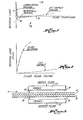
- FIG 1 a graph 10 which illustrates the load bearing characteristics of apparatus utilizing porous members to support a film therefrom.
- the horizontal axis represents the thickness of the fluid between the surface of the porous member and the film or object supported in spaced relation to that surface.
- the vertical axis represents the bearing load capacity of the apparatus. It will be recognized that the invention is suitable for heat sealing of varied materials, and for illustration only will be hereinafter referred to without intending any limitation, in connection with sealing thermoplastic films.
- the jet impact flow regime provided by the porous member is as described in the foregoing discussion. That is to say, fluid exudes from the porous surface of the porous member in a direction perpendicular to the film which is supported away from the porous surface. The exuding fluid creates a stagnant, non-moving boundary layer against the film. While in the jet impact flow regime, a positive bearing load is provided; this flow regime is limited by the various disadvantages described above, including the fact that the horizontal forces on the film do not net out to be zero. This tends to stress the film horizontally, causing wrinkles or other distortion. Also, the capacity of the apparatus to transfer heat from the fluid to the film is significantly reduced by the stagnant,.non-moving boundary layer.
- the film which is to be sealed moves through various distances away from the porous surface, as illustrated on the graph of Figure .1, it is subjected to significant stresses which provide turbulence and instability in the film.
- the load bearing capacity of the apparatus is a positive value (even though operation is in the jet impact flow regime).
- the film tends to move closer to the porous surface, however, it moves into the Bernoulli region where the film is drawn toward the porous surface. This fluctuation in the film causes the film to move and creates stresses therein which may cause distortion or wrinkling when the film is heated for sealing.
- the bearing load capacity increases significantly and the apparatus operates in an improved fluid bearing flow regime according to the invention wherein the fluid between the film to be sealed and the porous surface does not create a stagnant, non-moving boundary layer against the film.
- the fluid between the porous surface and the film moves in a generally horizontal direction, parallel to the porous surface and the film, and supports the film providing a significant bearing pressure.
- the laminar flow of the fluid is of such flow turbulence as to effectively transfer a significant portion of the heat of the fluid to the surface of the film for sealing.
- the tensions and stresses in the film are minimized by the fact that when the apparatus operates in fluid bearing flow regime, the horizontal forces acting on the film net out to be zero. This is accomplished even though substantial pressure is exerted on the film for the purposes of providing sufficient sealing compression.
- FIG 3 The operation of a sealing apparatus in accordance with this invention, and in the lubricating region or the fluid flow regime provided by the fluid bearing, is diagrammatically depicted in Figure 3.
- two porous elements 13 and 14 are disposed on either sides of two thermoplastic films A and B for sealing the films together.
- heated fluid is supplied to the porous members 13 and 14 such that the fluid is dispersed through the porous members and exudes from the surfaces 15 and l6.respectively thereof.
- the films A and B are handled so that they can be sealed while moving between the two porous members in the direction, for example, of the arrow C in the figure.
- the heated fluid heats the two films, and at the same time presses them together to cause complete sealing while the films move between the porous members.
- the length of the porous members when taken in conjection with the speed at which the film moves past the surfaces 15 and 16, and with the heat and pressure provided by the fluid operating in the fluid bearing flow regime, provides sufficient dwell time adequate to seal the films A and B together.
- the distances indicated at 17 and 18, respectively, in Figure 3 are approximately .001 inches and less, in order to insure that the sealing apparatus is operating in the true fluid bearing flow regime for a typical air fluid flow through the porous members.
- this distance may vary somewhat depending on the exact nature of the porous member and the characteristics and parameters of the fluid flowing through the porous member. It is important to note, however, that whatever the porosity of the member, and whatever the fluid flow rate, the appratus according to the invention is operated in the true fluid bearing flow regime and the distances 17 and 18 are not sufficiently large so that the apparatus could operateinthe Bernoulli region, or in the jet impact region as indicated in Figure 1, when sealing films.
- porous members which have been discussed above can be made from any material such as metals, for example, which are well known in the prior art.
- the members may be of any particular size or shape desired for the provision of a particular seal.
- such porous members may be made by any known process such as by sintering, for example.
- One particular porous member which we have found suitable is made and has the parameters which are described as follows:
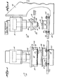
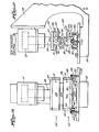
- the apparatus 20 comprises a known stationery heated bar heat sealer modified according to the invention.
- the particular heat sealer which has been modified a Model 205 Hot Die Blister Heat Sealer of the lab type is provided by Packaging Industries, Inc. of Hyannis, Massachusetts.
- This particular heat sealer was selected for modification since it included an air piston 21, a sturdy C-frame 22, and a base 23. These elements are structured to provide a sufficient distance between the lower end of the air piston 21 and the base 23 for the acceptance of sealing apparatus according to the invention as will be described herein.
- the lab sealer may also include stabilizer rods or bars extending from the top portion of the frame 22 downwardly for the purpose of engaging the apparatus mounted at the lower end 25 of the air piston in order to maintain it against rotation.
- Such devices may be spring loaded in order to assist the rapid return of the piston to an upper position such as that shown in Figures 4 and 5.
- the sealer has been modified, according to the invention, to include a fluid sealing apparatus 24 mounted at the lower end 25 of the air piston.
- the fluid sealing apparatus 24 includes a manifold 26, having forward and rearward walls 27 and 28, and end walls 29 and 30.
- a porous element 31 is disposed such that a lower porous face or surface 32 of the porous element 31 is directed in a downwardly direction.
- Such porous element is of a type which has already-been described.
- porous element 31 to the manifold 26 is perhaps best seen in Figures 6, 8 and 9, wherein the porous element is shown as being somewhat T-shaped. It is disposed at the bottom of the manifold 26 and, more particularly, within appropriate retaining slots 33 and 34 of the walls 27 and 28, respectively.
- heated fluid is pumped into the manifold 26 such as through the conduit 35, it fills the manifold, establishes a pressure, and them moves through the porous element-31, exuding from the porous surface 32 thereof.
- the apparatus 20 includes a back-up member such as a silicon rubber pad 39 mounted on a support plate 40.
- Plate 40 is mounted on two load cells 41 and 42 for the purpose of determining the pressure generated against the pad 39.
- the load cells 41 and 42 are mounted on an adjustable base plate 43 which is provided with a plurality of adjusting screws 44 for aligning the pad 39 in a horizontal plane.
- the load cells are connected to electronic calculation and readout means (not shown). These are calibrated to readout pressure values in terms of "P.S.I.” exerted on the films.
- air piston 21 of the apparatus 20 is energized by the application of air pressure through an air pressure control means (shown only diagrammatically in Figure 5)to lower the piston and to bring the porous member 31 into proximity with the pad 39 and two or more films which are disposed therebetween.
- the porous element must be brought close to the uppermost film and within a distance sufficient to provide a fluid bearing flowregime between the porous surface 32 and the film. More particularly, and in one embodiment, the porous surface 32 must be brought to within about .001 inch of the film in order to insure a fluid bearing flow regime operation with respect to sealing.
- heated fluid can be applied through the porous element at a predetermined flow rate, both to raise the temperatures of the films for sealing and to press them together for a , sufficient length of time that the films are appropriately sealed.
- FIG. 6 This example is illustrared in Figures 6 and 7.
- a single zone porous element 31 having porous surface 32 with a porosity of approximately 5 microns was mounted on the air piston and urged toward a silicon rubber backing pad to a distance varying from about .0005 to about .0015 therefrom.
- the porous surface was not parallel to the pad surface and the fluid bearing is thus considered to be unbalanced.
- Figure 6 of the drawings illustrates this set up: a heated fluid comprising hot air at a temperature of about 350OF was supplied to the porous element under approximately 20 psig, resulting in a through flow rate through the porous member of about 7 cfm.
- Example No. 2 is depicted in Figures 8 and 9 where the same apparatus as depicted in Figures 4 and 5 was utilized with the addition of two cold air knives 55 and 56 disposed alongside the manifold 26.
- Each air knife comprises an elongated tube running along the length of the manifold 26 on respective sides thereof.
- a plurality of apertures are drilled into the tube and face downwardly and inwardly in the directions of the arrows 56 and 58, Figure 8.
- Polypropylene films as described in Example No. 1 were disposed on the silicon rubber back-up pad 39 and the porous member 31 was lowered to a position spaced from the film.
- the porous surface 32 was disposed in relationship to the films 59 and 60 such that a fluid bearing flow regime was provided with respect to the air exuding from the surface 32 and between that surface and the film 59.
- the pressure applied to the film was on the order of 10 psi and the heated fluid was applied to the films for approximately 0.5 seconds. Also, as in Example No. 1, the fluid bearing was unbalanced such that the porous surface 32 was not exactly parallel to the silicon rubber pad 39.
- cooler air provided by the air knives 55 and 56 was directed at the edge areas of the seal.
- the cool air pressure within the air knives is approximately 50 psi.
- the set up depicted in Figure 8 was also utilized in connection with two low density polyethylene films of about 1 mil in thickness.
- the porous element 31 was lowered toward the film to a distance of approximately 0.001 inches and heated fluid was caused to flow through the porous element at a flow rate of about 4.1 cfm for a time of about 0.45 seconds.
- the bearing pressure on the film was approximately 20 psi; otherwise, this trial is similar to the trial discussed above in this example with respect to the polypropylene films.
- This operation on the polyethylene films produced a seal with substantially less edge distortion in the films at the closed side of the bearing than that in the polyethylene films produced in Example No. 1, but with severe distortion in the films at the open side of the bearing. Peel strength was measured at about 1.72 lbs./in.
- the reduction of the distortion, overall, is believed to be due to the balanced bearing, as a result of the parallelism of the porous surface and the back-up pad 39, and as a result of the temperature quenching air knives 55 and 56 at the edges of the heat seal.
- the seal produced by this operation in the polyethylene films was symmetrical, and was accompanied by edge weld distortion along the edges of the seal.Nevertheless, the seal and the level of distortion were substantially better than those of the polyethylene films in Example Nos. 1 and 2 above. Peel strength is measured at about 2.91 lbs./in.
- FIG 12 there is depicted therein a sealing apparatus:75 which is the same as the apparatus 20 shown in Figures 4 and 5, except for the type of back-up means utilized. Accordingly, similar parts of this apparatus are numbered the same as that of Figures 4 and 5 with the addition of a prime.
- the porous member 78 includes a porous surface 79 directed upwardly toward the porous surface 32' of the upper manifold 26'.
- the manifold 77 is provided with a conduit 80 for the conduction of heated fluid such as air thereto. Thus heated fluid can be directed into the manifold 77 and caused to flow through the porous member 78.
- thermoplastic films for example, are conveyed between the respective porous surfaces and the air piston is energized to lower the manifold 26 and thus the porous surface 32' toward the porous surface 79.
- the surface 32' is lowered to such a distance from the surface 79 that the characteristics of the heated fluid flow between each of the respective surfaces and the films which they face produce a fluid bearing flow regime having the advantages as discussed above. That is to say, that the nature of the fluid flow is sufficient to transfer a sufficient amount of heat and pressure from the fluid to the films to cause the films to seal while they move between the surfaces 32' and 79.
- the porous surfaces are maintained parallel to each other and to the films.
- similar heat and pressures as those described above in Examples 1 to 3 can be provided, the flow rates through the porous members and the fluid temperatures being selected to accomplish this result.
- the pressures provided by the bearing flow regimes are sufficient to press the films together during the dwell time when they are moved through the space between the two surfaces in order to provide a functional seal in the films.
- the films can be pulled through the area defined between the surfaces 32' and 79 in order to seal the films as the films are drawn therethrough.
- the dynamic sealing apparatus shown in Figure 12 is contrasted to the apparatus and operations described above which are directed to a static sealing situation.
- cool air knives (not shown in Figure 12) in connection with each of the upper and lower sealing elements 75 and 76 in order to reduce film distortion along the seals produced by this apparatus.
- Such knives can be disposed with respect to each sealing element as shown in Figure 10, for example.
- a dual zone sealing element such as those depicted in Figures 12 to 23 is provided.
- the dual zone porous body operates to heat and pressurize the films for sealing and to cool the films while they are within the confines of the same pressure area and fluid bearing flow regime. This operates to seal and to cool the films while at the same time minimizing distortion stresses exerted on the films while they are molten or soft.
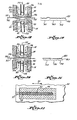
- FIG. 22 there is shown therein a dual zone porous body 90 as seen through two transparent thermoplastic films 92 moving in the direction of the arrow 93.
- the dual zone porous body 90 has a porous surface 94 ( Figure 14) divided into a central zone 95 and a surrounding zone 96. Heated fluid is directed through the porous body to the central zone 95 for the purpose of raising the temperature of the thermoplastic films for sealing and cooler fluid is directed to the surrounding zone 96 for the purpose of cooling the films immediately adjacent those portions of the film which are heated by virtue of the heated fluid exuded from the zone 95.
- the dual zone porous body 90 is operable to produce in the moving films 92 ' a seal 97 in an elongated area otherwise corresponding to the area 95 of the central zone of the porous surface 94.
- the surrounding zone or the cool zone of the porous body exudes cooler fluid therefrom so as to cool the films immedately adjacent the seal area 97, both along their side portions and at the downsteam end 98 of the central zone 95.
- the films are cooled, but cooling takes place while the films are under the same pressure profile.
- the films are thus not subjected to any interface or edge turbulences while they are molten or soft. This significantly reduces and in may cases eliminates edge weld or seal distortions and adjacent film puckering.
- the porous body 90 is integrally constructed with septum means 101 for separating the zones 95 and 96 of the porous body.
- Septum 101 comprises an elongated thin walled conduit member shaped to fit within the recess 102 of the porous body 90, that recess corresponding to the central zone 95 of the porous surface 94 of the porous body 90.
- the porous body may be made of the same materials and in the same general manner as the porous body of Figures 4 and 5.
- the septum is fitted into place integrally with the porous body.
- Spacer pins 103 are inserted into the septum as shown in Figure 13 and more particularly, in Figure 14 in expanded form.
- the pins can be secured in position by any suitable means, such as by welding, or press fitting.
- porous plug of similar material as the porous member could be inserted into the lower end of the septum, and an open celled foamed metal core may be inserted into the septum above the porous plug for the purpose of strengthening the septum.
- the porous member includes both the porous body 90, the septum 101 mounted in the recess 102 of the porous body 90, and the pins 103 disposed at a bottom end of the septum 101 and within the recess area 102.
- the porous body and the various elements 101 to 103 are mounted in a manifold 91 as shown in Figure 13.
- the manifold 91 includes two end walls 105 and 106, a top wall 107, and forward and rearward walls 108 and 109 (the forward wall 108 is not shown in Figure 13).
- the manifold 91 provides means for introducing heated and cooled fluids therein to the various zones of the porous body as will be described.
- a cooled fluid port 112 is provided at one end of the manifold 91 and .in, for example, the end wall 106.
- the heated fluid port 113 is directed into an upper area of the septum 101.
- the septum 101 extends into the top wall 107 of the manifold 91 and a heated fluid port 113 is provided in an upper area of the manifold 91 but at the same end thereof as the cooled fluid port 112.
- the heated fluid port 113 is constructed so that heated fluid is only admitted to the interior of the septum 101. Cooled fluid admitted through the port 112 is free to flow around the septum and above the porous body 90 within the manifold 91.
- the fluids preferably flow generally from one end of the manifold tcthe other in co-current flow directions; however, countercurrent flow has been demonstrated and might be preferred in some case.
- Both the cooled and the heated fluids are pressurized such that they can be made to flow through the porous body, the heated fluid exuding from the central zone 95 and the cooled fluid exuding from the surrounding zone 96 of the porous surface 94.
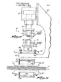
- a Model 205 Hot Die Blister Heat Sealer of the lab type as manufacturered by Packaging Industries Inc. of Hyannis, Massachusetts is utilized to support an upper sealing element 120 and a lower sealing element 121, each comprising dual zone elements as has been described with respect to Figures 13, 14 and 22.
- the lab sealer includes an air piston 21" mounted on a substantial C-frame 22".
- the air piston 21" is connected to an air pressure control means (Figure 17) for the purpose of pressurizing the air piston to lower the lower end 25" thereof so as to move the upper dual zone sealing apparatus 120 toward the lower dual zone sealing apparatus 121.
- the lab sealer may also include stabilizer rods or bars extending from the top portion of the frame 22" downwardly for the purpose of engaging the apparatus mounted at the lower end 25" of the air piston in order to maintain it against rotation.
- stabilizer rods or bars extending from the top portion of the frame 22" downwardly for the purpose of engaging the apparatus mounted at the lower end 25" of the air piston in order to maintain it against rotation.
- Such devices may be spring loaded in order to assist the rapid return of the piston to an upper position such as that shown in Figures 16 and 17.
- the upper dual zone sealing element 120 includes manifold 91 and the lower dual zone sealing apparatus 121 includes an identical 91 as has been described with. respect to Figures 13 and 14. These manifolds 91 are mounted so that their porous bodies 90 have their porous surfaces 94 facing each other.
- the upper dual zone sealing apparatus 120 includes a conduit 126 connected to port 113 for the purpose of introducing heated fluid into the interior of the septum 101.
- a second conduit 127 is connected to a port 112 for the purpose of introducing cooled fluid into the area of the manifold surrounding the septum 101.
- a conduit 128 is connected to a port 113 for the purpose of conducting heated fluid to the interior of the septum 101 and a conduit 129 is connected to a port 112' for the purpose of conducting cooled fluid to the area surrounding the septum 101.
- the upper and lower dual zone sealing apparatus 120 and 121 are mounted opposing each other and in corresponding relationship such that each has a central zone 95 and a surrounding zone 96 in their respective porous surfaces 94.
- the lower dual zone heat sealing element 121 is mounted so as to be adjustable in order to provide a very close parallel relationship between its porous surface 94 and the porous surface 94 of the upper heat sealing element 120.
- the lower dual zone heat sealing element 121 includes a bottom plate 132 indented to rest on a spherical bearing 133.
- Bearing 133 is mounted on a load cell 134 connected by means (not shown) to any appropriate electronic signal analyzing readout apparatus for indicating pressure exerted on the films between the sealing elements.
- Each end of the-manifold 91 of the lower'dual zone heat sealing element 121 is provided with two pins 135 extending therefrom.
- Bolts 136 and 137 are mounted in a base, plate 138 of the C-frame 22" and have their heads disposed over the pins 135. Ideally, when the manifold 91 is properly positioned, the heads of the bolts 136 and 137 will not engage the pins or the ends of the manifold, rather these bolts are simply provided for the purpose of maintaining a near parallel relationship of the porous surfaces 94-94 and act as a stop to keep the lower manifold 91 and porous surface 94 from rotating or moving severly from horizontal plane.
- the lower manifold 91 is also positioned by means of a pair of diagonally oriented out rigger shafts 139 and 140, each of which are supported by respective scissor jacks 141 and 142.
- the jacks are adjustable so that the entire manifold, through the means of the jacks and the outriggers 139 and 140, can be angularly rotated and moved on the bearing 133 in order to have the lower porous surface 94 thereof paralleled with the upper porous surface which is fixed in a horizontal disposition.
- the manifolds may be more precisely aligned without requiring this type of adjustment means as has been described.
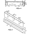
- porous surfaces 94 are not entirely flat, but are tapered along their edges and at their ends adjacent a central flat area of surface 94.
- These tapers are shown in Figures 13, 14, 17, 18 and 20. As will be described, these tapers are not necessarily coextensive with zone 96 of surface 94, but in a preferred embodiment are located totally within such zones.
- the tapers are functional to define flow interface areas between the central flat area 146 and the exterior of the sealing element.
- the porous surfaces 94 of the upper and lower porous bodies 90 include opposedly oriented flat areas 145 and 146 in which the heated zone 95 of each porous surface is located and in which a portion of the cooler zone 96 of each porous surface is located. While the cool zone 96 totally surrounds the heated zone 95, there is preferably no specific definition in the porous surface itself of the demarcation between the zones 95 and 96. Accordingly, it will be appreciated that the septums 101 are inserted into the porous bodies 90 to a depth such that the zones in the porous surfaces 94 are rather well defined by the temperatures differentials of the fluids which are conducted through the porous body from the interior of the septum and from the exterior of the septum into two different zones.
- the air pressure control is energized to lower the air piston 21 and thus to lower the upper porous surface 94 toward the lower porous surface 94.
- films such as those indicated at 92 in Figure 22 are disposed to be drawn through the space between the opposed porous surfaces 94 while heated fluid is supplied through the interior of the septums 101 in order to seal the films in the predetermined area 97 ( Figure 22) as the films are moved therethrough.
- the porous surfaces 94 are disposed close enough to each other such that they generate a true fluid bearing flow regime between each of the surfaces respectively and the films drawn therebetween. Accordingly the porous surfaces are disposed at a distance which corresponds to the distance from zero to the point 12 in the graph shown in Figure 1 of the drawings and, preferably, at a distance somewhere between zero and the point 12 in order to provide a suitable bearing load on the films as the films are drawn therethrough.
- Examples 4 and 5 illustrates the use of the apparatus as has been described in connection with a sealing operation wherein two films are sealed together ( Figure 15).
- the appratus as has been described and particularly the dual zone porous members can be utilized in any form of sealing operation where it is desired to heat seal sealable materials together.
- the apparatus will be described in connection with the sealing of two flat films, the dual zone porous bodies described herein could be used in connection with sealing films to other types of materials and for sealing other kinds of materials to each other in both flat and configured shaped.
- the films 151 and 152 comprise the same polypropylene films described above in the foregoing examples 1 to 3 with the exception that the polypropylene is .085 gauge.
- Hot fluid at a temperature of approximately 225°F was supplied to the respective upper and lower septums 101 as indicated by the arrows 155.
- Cooler fluid at approximately 73°F was supplied to the respective manifolds as indicated by the arrows 156.
- the flow rate of the heated fluid at about 225°F measured approximately 4.5 cfm (at 22 psi and 73 0 F temperature before the fluid was heated).
- the flow rate of the cool fluid was approximately 9.4 cfm at 35 psig manifold pressure.
- the resulting pressure on the films exerted by the fluid bearing flow regime supporting each film was approximately 2 psi, and the film was drawn between the porous bodies at a speed such that an arbitrary point on the moving film dwelled within the elongated heated zone 95 ( Figure 22) for approximately .2 seconds.
- low density polyethylene films of approximately 1 mil in thickness were drawn through and between the two porous bodies 90.
- the temperature of the heated fluid was approximately 260°F and the.films were drawn between the porous bodies at a speed corresponding to a dwell time of any arbitrary point on the film of about .2 seconds.
- the flow rate of the heated fluid through the porous bodies was approximately 8.2 cfm and the flow rate of the cool fluid through the porous bodies was approximately 6.8 cfmr
- the pressure exerted by the bearings on the film was approximately 3 psi.
- the apparatus is set up as illustrated in Figure 20 and polypropylene films 166 and 167 (like films 151 and 152) were drawn between the porous bodies 90 to effect a seal between the films.
- the apparatus was adjusted so that the porous surfaces and particularly the flat areas 145 and 146 were parallel to each other.
- the porous bodies were brought toward each other by means of the air piston such that there was approximately .001 inch between the respective surfaces 145 and 146 and the respective films 167 and 166 which face those surfaces.
- the parallelism of the porous surfaces 145 and 146 were maintained within a tolerance of about 0.0005 inches, and the bearing provided by the fluid exuded from the porous bodies was thus considered to be balanced.
- Other factors were the same as Example No. 4.
- the seal produced in the. polypropylene films was as is shown in Figure 21 and was of commercially acceptable quality for openly visual seals. Peel strength, measured as described above, was about 0.70 lbs./in.
- a seal 172 area was provided between the films 166 and 167 between unsealed areas 173 and 174.
- the seal provided was without significant distortion and, furthermore, the films in the areas 173 and 174 adjacent the seal area 172 were also substantially without distortion or puckering, producing a commercially and visually acceptable seal. Any slight film waviness appearing in areas 173 and 174 were believed to be caused by a slight tracking wander of the films as they were hand drawn through the sealer. Of course, in a production apparatus, the film would be very stably handled by any suitable mechanical means, preferably outside the bearing areas, and all waviness would be potentially eliminated.
- the methods and apparatus described herein provide a non- physical contact sealing process, capable of transferring sufficient heat and pressure to two or more layers of thermoplastic films within a well defined area and then cooling the films while still under the same pressure, in order to prevent distortion or puckering in the seal area or in the films adjacent the seal area.
- the sealing and simultaneous cooling of the preferred embodiment all take place within a well defined true fluid bearing flow regime area such that the forces imparted to the molten or softened film by the characteristics of the fluid net out to be zero, thereby reducing film tension and stresses which cause distortion. Accordingly,the films is cooled along its edges and along its leading edge before it must be removed from the fluid bearing area. The time in which the film must remain molten or soft for sealing, and during which the film must be handled, is substantially reduced.
- FIG 23 A modification of the preferred embodiment of the invention is shown in Figure 23. This modification contemplates the use of a single element, but dual zone seal like that of Figures 13 through 22, but cooperating statically with a silicon rubber back-up pad 39"' like that of Figures 4 and 5.
- Fig. 23 The features of the apparatus shown in Fig. 23 are designated by primed numbers corresponding to the apparatus shown in Figs. 4 and 5 with the exception of the dual zone sealing element 176"' which corresponds to the upper sealing element 120 of the preferred embodiment as shown in Figs. 16 and 17. Accordingly, the features of the dual zone single element 176"' in Fig. 23, which are identical to those of the upper sealing element 120 of Fig. 17, are shown also with triple primed numbers.
- the operation of the modified embodiment of Fig. 23 is similar to that operation of the apparatus of Figs. 4 and 5 with the exception that the dual zone sealing element 176"' is operative to provide an improved seal in heat sealable materials such as films as have been described. Utilization of the dual zone sealing element in connection with the back-up means or silicon rubber pad 39" as shown in Fig. 23 is useful where it is desired to produce a seal in stationary films, for example.
- thermoplastic films are disposed on the pad 39"' and the surface 94"' is lowered by piston 21"' to a distance from the films such that a true fluid bearing flow regime is established between the surface 94"' and the films.for sealing them together. Heated fluid through a central heated zone in surface 94"' heats and pressurizes the films for sealing while cooler fluid in a.cooler surrounding zone of surface 94"' continues to pressurize the films but cools them also.
- Fig. 12 has included apparatus suitable for producing seals in films moving in a dynamic fashion, such as where the fluid bearing is produced on each side of the film. It is important to note, however, that the static- apparatus disclosed in Fig. 23, and in Figs.. 4 and 5, utilizing a stationary back-up pad, are suitable for producing seals either when the film is stationary, or when moving and the sealing apparatus is constructed to move cyclically-with the films and not relative thereto during sealing.
- the sealing element 176"' and the back-up pad 39"' could be positioned to cyclically approach and seal the film when the film is intermittently held stationary.
- the element 176"' and pad 39"' are respectively mounted on rotating members to move the sealing element and the back-up pad along with the film in order to produce a seal therein as the film continuously moves.
- the preferred dual zone porous member described herein is particularly advantageous when any intermittent film motion or intermittent sealing is contemplated.
- one advantage obtained by the dual zoning concept of the invention is the possibility to quickly and efficiently vary the temperature of.the fluids to rapid control the heat applied to the films. Because the fluids are heated at a distance from the manifolds 91, cooling fluid can be instantaneously vented into the septum 101 for cooling zone 95 immediately. This could eliminate burning of the films when they may be stopped in the bearing area. Also, intermittent heating and cooling of fluid supplied to the septum 101 could be used to produce intermittent seals in films moving continuously through the area seal/without changing the pressure profile through which the film moves. This would substantially reduce or eliminate film distortion or puckering.
- the temperature of the fluids can be controlled even for intermittent seals, the films always being in the same fluid bearing pressure profile when molten or softened.
- the ability to instantaneously apply preheated fluid through septum 101 eliminates poor sealing due to insufficient heat on any start-up of the operation.
- the independent gas flows can be used to provide for control of temperature transition rate changes between the zones in the face areas of the porous body.
- multiple zoned porous bodies could be provided for obtaining a plurality of seals in a single sealing operation.
- Multiple temperatures in connection with multiple zones in a porous body can be used for the adjustement of seal width, seal strength, and desired edge definition.
- the variable bearing stiffness in each of the zones can be adjusted in order to accomplish desired package of film alignment in addition to desired sealing width, strength and edge definition.
- bearing sealing elements could be used within the scope of the invention.
- a single elongated bearing element on one film side and two separate bearing elements on the opposing side could be used to permit sequential joining of two films, then an additional film thereto, the additional film being introduced between the two separated bearing elements.
- Many other seal and material configurations can be readily appreciated and produced by the use of either multiple zones, multiple sealer elements, or combinations or both.
- pressures lower than atmospheric pressures can be used to advantage in the zones of the porous air bearing sealing elements.
- a negative pressure in the outer zone surrounding the hot , zone in a dual zone bearing element can be induced by reducing pressure in the manifold chamber surrounding septum 101.
- This can be done by a vacuum pump or any suitable means connected to port 112 ( Figure 13) and will function to draw off the hot air through the porous member and in the corresponding outer zone area, and will thus also cool the film adjacent the hot zone within the seal area.
- Such operation may be highly desirable in certain areas where the materials do not tend to stick to the bearing elements or where opposed bearing elements permit pressure balancing for film control.
- a further application of the invention is found in the handling of seals in materials of, or covering, various shapes.
- the porous elements can be moulded to many different shapes to accommodate varied sealing area configurations as desired, and can be used where the product or article to be sealed within the film forms the back-up support for sealing.
- a variety of materials may be sealed by utilizing the concepts and the processes provided by this invention.
- Polypropylene, polyethylene and other homogeneous and heterogeneous films for flexible packaging or laminated film or paper could be handled by this process as well as various multi-layered films and coated porous substrates such as hot melt adhesive coated paper or plastic film laminated to paper or to woven or non-woven textiles. All of these can be handled according to the processes of the invention, desribed herein, and thus the term "heat sealing” includes sealing of films together by rendering the films at least tacky for sealing, or by heating at least a coating on the films for sealing purposes.
- the invention also broadly contemplates other forms of sealing or pressurization of films or webs where heat is not required or does not play a critical part.
- the invention is particularly useful for sealing materials tagether through the expedient of pressure-sensitive adhesives or of gas or steam-activated adhesives which do not require the application of heat, but only of sufficient sealing pressure.
- one pressure adhesive coated web could be pressed against and sealed to another by conveying or placing them between any sealing element and back-up means (including conveyance between two sealing elements) as described herein.
- the fluid bearing flow regime could be maintained so as to provide significant sealing pressures to promote sealing.
- the apparatus described herein including a silicon rubber back-up pad, is particularly useful for continuous pressure-sensitive sealing since the coated film is not usually rendered molten and sliding of it across the back-up pad would not be determined.
- single or dual sealing elements of single or multiple zones thus can advantageously be used for sealing without requiring supplemental sealing pressures such as by direct contact rollers, pads and the like.
- the invention provides for the utilization of a true fluid bearing flow regime for the purpose of sealing materials together.
- the invention also contemplates the utilization of a dual zone heat sealing porous member for the purpose of heating heat-sealable materials and for cooling such materials while the materials remain in the fluid bearing flow area in order to eliminate distortion or puckering in the seals and in the films.
Landscapes
- Engineering & Computer Science (AREA)
- Mechanical Engineering (AREA)
- Physics & Mathematics (AREA)
- Fluid Mechanics (AREA)
- Chemical & Material Sciences (AREA)
- Combustion & Propulsion (AREA)
- Processing And Handling Of Plastics And Other Materials For Molding In General (AREA)
- Casting Or Compression Moulding Of Plastics Or The Like (AREA)
- Lining Or Joining Of Plastics Or The Like (AREA)
Applications Claiming Priority (2)
| Application Number | Priority Date | Filing Date | Title |
|---|---|---|---|
| US16837680A | 1980-07-10 | 1980-07-10 | |
| US168376 | 1980-07-10 |
Publications (2)
| Publication Number | Publication Date |
|---|---|
| EP0044206A2 true EP0044206A2 (de) | 1982-01-20 |
| EP0044206A3 EP0044206A3 (de) | 1984-05-02 |
Family
ID=22611265
Family Applications (1)
| Application Number | Title | Priority Date | Filing Date |
|---|---|---|---|
| EP19810303168 Withdrawn EP0044206A3 (de) | 1980-07-10 | 1981-07-10 | Schweissverfahren und -vorrichtung |
Country Status (2)
| Country | Link |
|---|---|
| EP (1) | EP0044206A3 (de) |
| JP (1) | JPS5766919A (de) |
Cited By (14)
| Publication number | Priority date | Publication date | Assignee | Title |
|---|---|---|---|---|
| EP2248657A3 (de) * | 2009-05-06 | 2015-03-18 | MS Spaichingen GmbH | Vorrichtung zum Verbinden von Gegenständen über wenigstens ein durch Wärme plastifizierbares Verbindungselement |
| US9603752B2 (en) | 2010-08-05 | 2017-03-28 | Curt G. Joa, Inc. | Apparatus and method for minimizing waste and improving quality and production in web processing operations by automatic cuff defect correction |
| US9622918B2 (en) | 2006-05-18 | 2017-04-18 | Curt G. Joe, Inc. | Methods and apparatus for application of nested zero waste ear to traveling web |
| US9809414B2 (en) | 2012-04-24 | 2017-11-07 | Curt G. Joa, Inc. | Elastic break brake apparatus and method for minimizing broken elastic rethreading |
| US9907706B2 (en) | 2011-02-25 | 2018-03-06 | Curt G. Joa, Inc. | Methods and apparatus for forming disposable products at high speeds with small machine footprint |
| US9944487B2 (en) | 2007-02-21 | 2018-04-17 | Curt G. Joa, Inc. | Single transfer insert placement method and apparatus |
| US9950439B2 (en) | 2007-02-21 | 2018-04-24 | Curt G. Joa, Inc. | Single transfer insert placement method and apparatus with cross-direction insert placement control |
| US10167156B2 (en) | 2015-07-24 | 2019-01-01 | Curt G. Joa, Inc. | Vacuum commutation apparatus and methods |
| US10456302B2 (en) | 2006-05-18 | 2019-10-29 | Curt G. Joa, Inc. | Methods and apparatus for application of nested zero waste ear to traveling web |
| US10751220B2 (en) | 2012-02-20 | 2020-08-25 | Curt G. Joa, Inc. | Method of forming bonds between discrete components of disposable articles |
| WO2021001269A1 (de) * | 2019-07-02 | 2021-01-07 | Ewald Wegner | Düsenvorrichtung und heissgasschweissanlage |
| DE102019130670A1 (de) * | 2019-11-13 | 2021-05-20 | Precon Engineering GmbH | Heizelement, Vorrichtung und Verfahren zum Heißgasschweißen von Kunststoffteilen |
| US11737930B2 (en) | 2020-02-27 | 2023-08-29 | Curt G. Joa, Inc. | Configurable single transfer insert placement method and apparatus |
| CN117863497A (zh) * | 2024-02-29 | 2024-04-12 | 无锡中油瑞德防腐科技有限公司 | 一种钢质弯管缠绕三层结构聚乙烯涂层制备设备 |
Families Citing this family (35)
| Publication number | Priority date | Publication date | Assignee | Title |
|---|---|---|---|---|
| US8417374B2 (en) | 2004-04-19 | 2013-04-09 | Curt G. Joa, Inc. | Method and apparatus for changing speed or direction of an article |
| US7703599B2 (en) | 2004-04-19 | 2010-04-27 | Curt G. Joa, Inc. | Method and apparatus for reversing direction of an article |
| US7640962B2 (en) | 2004-04-20 | 2010-01-05 | Curt G. Joa, Inc. | Multiple tape application method and apparatus |
| US20050230037A1 (en) | 2004-04-20 | 2005-10-20 | Curt G. Joa, Inc. | Staggered cutting knife |
| US7708849B2 (en) | 2004-04-20 | 2010-05-04 | Curt G. Joa, Inc. | Apparatus and method for cutting elastic strands between layers of carrier webs |
| US7638014B2 (en) | 2004-05-21 | 2009-12-29 | Curt G. Joa, Inc. | Method of producing a pants-type diaper |
| US7537215B2 (en) | 2004-06-15 | 2009-05-26 | Curt G. Joa, Inc. | Method and apparatus for securing stretchable film using vacuum |
| US7811403B2 (en) | 2005-03-09 | 2010-10-12 | Curt G. Joa, Inc. | Transverse tab application method and apparatus |
| CA2600432C (en) | 2005-03-09 | 2013-07-16 | Curt G. Joa, Inc. | Transverse tape application method and apparatus |
| US8007484B2 (en) | 2005-04-01 | 2011-08-30 | Curt G. Joa, Inc. | Pants type product and method of making the same |
| US7618513B2 (en) | 2005-05-31 | 2009-11-17 | Curt G. Joa, Inc. | Web stabilization on a slip and cut applicator |
| US7533709B2 (en) | 2005-05-31 | 2009-05-19 | Curt G. Joa, Inc. | High speed vacuum porting |
| US7770712B2 (en) | 2006-02-17 | 2010-08-10 | Curt G. Joa, Inc. | Article transfer and placement apparatus with active puck |
| US8172977B2 (en) | 2009-04-06 | 2012-05-08 | Curt G. Joa, Inc. | Methods and apparatus for application of nested zero waste ear to traveling web |
| US9433538B2 (en) | 2006-05-18 | 2016-09-06 | Curt G. Joa, Inc. | Methods and apparatus for application of nested zero waste ear to traveling web and formation of articles using a dual cut slip unit |
| US8016972B2 (en) | 2007-05-09 | 2011-09-13 | Curt G. Joa, Inc. | Methods and apparatus for application of nested zero waste ear to traveling web |
| US7780052B2 (en) | 2006-05-18 | 2010-08-24 | Curt G. Joa, Inc. | Trim removal system |
| PL1961403T3 (pl) | 2007-02-21 | 2022-10-17 | Curt G. Joa, Inc. | Sposób i urządzenie do rozmieszczania wkładki z pojedynczym przeniesieniem |
| US8398793B2 (en) | 2007-07-20 | 2013-03-19 | Curt G. Joa, Inc. | Apparatus and method for minimizing waste and improving quality and production in web processing operations |
| US9387131B2 (en) | 2007-07-20 | 2016-07-12 | Curt G. Joa, Inc. | Apparatus and method for minimizing waste and improving quality and production in web processing operations by automated threading and re-threading of web materials |
| US8182624B2 (en) | 2008-03-12 | 2012-05-22 | Curt G. Joa, Inc. | Registered stretch laminate and methods for forming a registered stretch laminate |
| US8673098B2 (en) | 2009-10-28 | 2014-03-18 | Curt G. Joa, Inc. | Method and apparatus for stretching segmented stretchable film and application of the segmented film to a moving web |
| US9089453B2 (en) | 2009-12-30 | 2015-07-28 | Curt G. Joa, Inc. | Method for producing absorbent article with stretch film side panel and application of intermittent discrete components of an absorbent article |
| US8460495B2 (en) | 2009-12-30 | 2013-06-11 | Curt G. Joa, Inc. | Method for producing absorbent article with stretch film side panel and application of intermittent discrete components of an absorbent article |
| US8663411B2 (en) | 2010-06-07 | 2014-03-04 | Curt G. Joa, Inc. | Apparatus and method for forming a pant-type diaper with refastenable side seams |
| US8656817B2 (en) | 2011-03-09 | 2014-02-25 | Curt G. Joa | Multi-profile die cutting assembly |
| USD684613S1 (en) | 2011-04-14 | 2013-06-18 | Curt G. Joa, Inc. | Sliding guard structure |
| US8820380B2 (en) | 2011-07-21 | 2014-09-02 | Curt G. Joa, Inc. | Differential speed shafted machines and uses therefor, including discontinuous and continuous side by side bonding |
| US9283683B2 (en) | 2013-07-24 | 2016-03-15 | Curt G. Joa, Inc. | Ventilated vacuum commutation structures |
| USD703248S1 (en) | 2013-08-23 | 2014-04-22 | Curt G. Joa, Inc. | Ventilated vacuum commutation structure |
| USD703711S1 (en) | 2013-08-23 | 2014-04-29 | Curt G. Joa, Inc. | Ventilated vacuum communication structure |
| USD704237S1 (en) | 2013-08-23 | 2014-05-06 | Curt G. Joa, Inc. | Ventilated vacuum commutation structure |
| USD703712S1 (en) | 2013-08-23 | 2014-04-29 | Curt G. Joa, Inc. | Ventilated vacuum commutation structure |
| USD703247S1 (en) | 2013-08-23 | 2014-04-22 | Curt G. Joa, Inc. | Ventilated vacuum commutation structure |
| US9289329B1 (en) | 2013-12-05 | 2016-03-22 | Curt G. Joa, Inc. | Method for producing pant type diapers |
Family Cites Families (10)
| Publication number | Priority date | Publication date | Assignee | Title |
|---|---|---|---|---|
| US3311525A (en) * | 1963-10-02 | 1967-03-28 | Union Carbide Corp | Heat sealing apparatus including a porous member and fluid pressure |
| US3488244A (en) * | 1965-01-21 | 1970-01-06 | Albemarle Paper Mfg Co | Heat sealing apparatus |
| GB1079430A (en) * | 1965-05-06 | 1967-08-16 | Maxbo Ab | A method and apparatus for heat sealing or cutting thermoplastic material |
| CH439064A (de) * | 1965-07-09 | 1967-06-30 | Hesser Ag Maschf | Verfahren zum Herstellen von Klebeverbindungen an Verschlussteilen von beutelartigen Verpackungsbehältern und Vorrichtung zur Durchführung des Verfahrens |
| DE1604687A1 (de) * | 1966-09-12 | 1970-12-17 | Produktionsgenossenschaft Des | Verfahren zum Schweissen von Plastfolien,insbesondere Polyaethylenfolien und Vorrichtung zur Durchfuehrung des Verfahrens |
| GB1309941A (en) * | 1970-01-07 | 1973-03-14 | Mardon Son Hall Ltd | Method and apparatus for sealing cartons |
| JPS4879677U (de) * | 1971-12-29 | 1973-09-29 | ||
| US3825408A (en) * | 1973-09-07 | 1974-07-23 | Phillips Petroleum Co | Hot air heater for carton sealing machine |
| JPS5431417Y2 (de) * | 1974-10-04 | 1979-10-01 | ||
| DE2630460A1 (de) * | 1976-07-07 | 1978-01-12 | Bosch Gmbh Robert | Vorrichtung zum herstellen eines schlauches aus einer packstoffbahn |
-
1981
- 1981-07-10 JP JP10724281A patent/JPS5766919A/ja active Pending
- 1981-07-10 EP EP19810303168 patent/EP0044206A3/de not_active Withdrawn
Cited By (24)
| Publication number | Priority date | Publication date | Assignee | Title |
|---|---|---|---|---|
| US9622918B2 (en) | 2006-05-18 | 2017-04-18 | Curt G. Joe, Inc. | Methods and apparatus for application of nested zero waste ear to traveling web |
| US10456302B2 (en) | 2006-05-18 | 2019-10-29 | Curt G. Joa, Inc. | Methods and apparatus for application of nested zero waste ear to traveling web |
| US10266362B2 (en) | 2007-02-21 | 2019-04-23 | Curt G. Joa, Inc. | Single transfer insert placement method and apparatus |
| US9944487B2 (en) | 2007-02-21 | 2018-04-17 | Curt G. Joa, Inc. | Single transfer insert placement method and apparatus |
| US9950439B2 (en) | 2007-02-21 | 2018-04-24 | Curt G. Joa, Inc. | Single transfer insert placement method and apparatus with cross-direction insert placement control |
| US10702428B2 (en) | 2009-04-06 | 2020-07-07 | Curt G. Joa, Inc. | Methods and apparatus for application of nested zero waste ear to traveling web |
| EP2248657A3 (de) * | 2009-05-06 | 2015-03-18 | MS Spaichingen GmbH | Vorrichtung zum Verbinden von Gegenständen über wenigstens ein durch Wärme plastifizierbares Verbindungselement |
| US9603752B2 (en) | 2010-08-05 | 2017-03-28 | Curt G. Joa, Inc. | Apparatus and method for minimizing waste and improving quality and production in web processing operations by automatic cuff defect correction |
| USRE48182E1 (en) | 2010-08-05 | 2020-09-01 | Curt G. Joa, Inc. | Apparatus and method for minimizing waste and improving quality and production in web processing operations by automatic cuff defect correction |
| US9907706B2 (en) | 2011-02-25 | 2018-03-06 | Curt G. Joa, Inc. | Methods and apparatus for forming disposable products at high speeds with small machine footprint |
| US10751220B2 (en) | 2012-02-20 | 2020-08-25 | Curt G. Joa, Inc. | Method of forming bonds between discrete components of disposable articles |
| US9809414B2 (en) | 2012-04-24 | 2017-11-07 | Curt G. Joa, Inc. | Elastic break brake apparatus and method for minimizing broken elastic rethreading |
| US9908739B2 (en) | 2012-04-24 | 2018-03-06 | Curt G. Joa, Inc. | Apparatus and method for applying parallel flared elastics to disposable products and disposable products containing parallel flared elastics |
| US11034543B2 (en) | 2012-04-24 | 2021-06-15 | Curt G. Joa, Inc. | Apparatus and method for applying parallel flared elastics to disposable products and disposable products containing parallel flared elastics |
| US10633207B2 (en) | 2015-07-24 | 2020-04-28 | Curt G. Joa, Inc. | Vacuum commutation apparatus and methods |
| US10494216B2 (en) | 2015-07-24 | 2019-12-03 | Curt G. Joa, Inc. | Vacuum communication apparatus and methods |
| US10167156B2 (en) | 2015-07-24 | 2019-01-01 | Curt G. Joa, Inc. | Vacuum commutation apparatus and methods |
| WO2021001269A1 (de) * | 2019-07-02 | 2021-01-07 | Ewald Wegner | Düsenvorrichtung und heissgasschweissanlage |
| DE102019117868A1 (de) * | 2019-07-02 | 2021-01-07 | Ewald Wegner | Düsenvorrichtung und Heißgasschweißanlage |
| DE102019117868B4 (de) | 2019-07-02 | 2022-02-03 | Ewald Wegner | Düsenvorrichtung und Heißgasschweißanlage |
| DE102019130670A1 (de) * | 2019-11-13 | 2021-05-20 | Precon Engineering GmbH | Heizelement, Vorrichtung und Verfahren zum Heißgasschweißen von Kunststoffteilen |
| DE102019130670B4 (de) | 2019-11-13 | 2022-08-18 | Precon Engineering GmbH | Heizelement, Vorrichtung und Verfahren zum Heißgasschweißen von Kunststoffteilen |
| US11737930B2 (en) | 2020-02-27 | 2023-08-29 | Curt G. Joa, Inc. | Configurable single transfer insert placement method and apparatus |
| CN117863497A (zh) * | 2024-02-29 | 2024-04-12 | 无锡中油瑞德防腐科技有限公司 | 一种钢质弯管缠绕三层结构聚乙烯涂层制备设备 |
Also Published As
| Publication number | Publication date |
|---|---|
| JPS5766919A (en) | 1982-04-23 |
| EP0044206A3 (de) | 1984-05-02 |
Similar Documents
| Publication | Publication Date | Title |
|---|---|---|
| EP0044206A2 (de) | Schweissverfahren und -vorrichtung | |
| US4350545A (en) | Method of laminating plastic sheets | |
| US4545844A (en) | Heat cutting and sealing apparatus | |
| US4105491A (en) | Process and apparatus for the manufacture of embossed film laminations | |
| US8905110B2 (en) | Machine and methods for the manufacture of air-filled cushions | |
| US20130228278A1 (en) | Process for Making Inflatable Article | |
| EP0701954A4 (de) | Verfahren und vorrichtung zur herstellung von luftpolstern | |
| JPH0764343B2 (ja) | 液状製品の連続熱処理・包装方法及びその装置 | |
| US3421960A (en) | Bonding technique and apparatus for plastic structures | |
| US20250223062A1 (en) | Forming device and method for forming a cup into a packaging material | |
| US4950354A (en) | Method of making a micro-bubble laminate | |
| HU211410B (en) | Device for heating platelike bodies made of deep-drawing plastic material | |
| US8956146B2 (en) | Apparatus for embossing a web | |
| US3070481A (en) | Method of making an inflatable article from thermoplastic films | |
| EP0055082A2 (de) | Tiefgezogene Gegenstände | |
| JP2017100774A (ja) | 超音波シール方法及び装置 | |
| US11279094B2 (en) | Heat-sealing apparatus and method for forming composite heat seal structure | |
| KR200267371Y1 (ko) | 에어캡 완충시트 제조장치 및 완충시트 | |
| US3514362A (en) | Apparatus for manufacturing cellular material | |
| JPH0133336B2 (de) | ||
| JPH01125214A (ja) | 熱可塑性樹脂シ−ト類の熱成形方法とその装置 | |
| JP2001151208A (ja) | 包装装置及び包装体 | |
| US3322594A (en) | Method of controlling the bond between a pad and a plastic sheet | |
| US8409394B2 (en) | Fluid pressure lamination system | |
| CN223045147U (zh) | 一种箱包冲压成型设备 |
Legal Events
| Date | Code | Title | Description |
|---|---|---|---|
| PUAI | Public reference made under article 153(3) epc to a published international application that has entered the european phase |
Free format text: ORIGINAL CODE: 0009012 |
|
| AK | Designated contracting states |
Designated state(s): DE FR GB IT |
|
| PUAL | Search report despatched |
Free format text: ORIGINAL CODE: 0009013 |
|
| AK | Designated contracting states |
Designated state(s): DE FR GB IT |
|
| STAA | Information on the status of an ep patent application or granted ep patent |
Free format text: STATUS: THE APPLICATION IS DEEMED TO BE WITHDRAWN |
|
| 18D | Application deemed to be withdrawn |
Effective date: 19850103 |
|
| RIN1 | Information on inventor provided before grant (corrected) |
Inventor name: SMITH, JAMES C. Inventor name: HUDDLESTON, ROBERT J. Inventor name: COBBS, WALTER H., JR. |