EP0043771B1 - Werkzeug zum Erzeugen von Löchern in Faserwerkstoffen - Google Patents
Werkzeug zum Erzeugen von Löchern in Faserwerkstoffen Download PDFInfo
- Publication number
- EP0043771B1 EP0043771B1 EP81401069A EP81401069A EP0043771B1 EP 0043771 B1 EP0043771 B1 EP 0043771B1 EP 81401069 A EP81401069 A EP 81401069A EP 81401069 A EP81401069 A EP 81401069A EP 0043771 B1 EP0043771 B1 EP 0043771B1
- Authority
- EP
- European Patent Office
- Prior art keywords
- tool
- flute
- cutting
- end point
- edge
- Prior art date
- Legal status (The legal status is an assumption and is not a legal conclusion. Google has not performed a legal analysis and makes no representation as to the accuracy of the status listed.)
- Expired
Links
Images
Classifications
-
- B—PERFORMING OPERATIONS; TRANSPORTING
- B23—MACHINE TOOLS; METAL-WORKING NOT OTHERWISE PROVIDED FOR
- B23B—TURNING; BORING
- B23B51/00—Tools for drilling machines
- B23B51/04—Drills for trepanning
-
- B—PERFORMING OPERATIONS; TRANSPORTING
- B26—HAND CUTTING TOOLS; CUTTING; SEVERING
- B26F—PERFORATING; PUNCHING; CUTTING-OUT; STAMPING-OUT; SEVERING BY MEANS OTHER THAN CUTTING
- B26F1/00—Perforating; Punching; Cutting-out; Stamping-out; Apparatus therefor
- B26F1/16—Perforating by tool or tools of the drill type
-
- B—PERFORMING OPERATIONS; TRANSPORTING
- B23—MACHINE TOOLS; METAL-WORKING NOT OTHERWISE PROVIDED FOR
- B23B—TURNING; BORING
- B23B2226/00—Materials of tools or workpieces not comprising a metal
- B23B2226/27—Composites
-
- Y—GENERAL TAGGING OF NEW TECHNOLOGICAL DEVELOPMENTS; GENERAL TAGGING OF CROSS-SECTIONAL TECHNOLOGIES SPANNING OVER SEVERAL SECTIONS OF THE IPC; TECHNICAL SUBJECTS COVERED BY FORMER USPC CROSS-REFERENCE ART COLLECTIONS [XRACs] AND DIGESTS
- Y10—TECHNICAL SUBJECTS COVERED BY FORMER USPC
- Y10T—TECHNICAL SUBJECTS COVERED BY FORMER US CLASSIFICATION
- Y10T407/00—Cutters, for shaping
- Y10T407/19—Rotary cutting tool
- Y10T407/1946—Face or end mill
-
- Y—GENERAL TAGGING OF NEW TECHNOLOGICAL DEVELOPMENTS; GENERAL TAGGING OF CROSS-SECTIONAL TECHNOLOGIES SPANNING OVER SEVERAL SECTIONS OF THE IPC; TECHNICAL SUBJECTS COVERED BY FORMER USPC CROSS-REFERENCE ART COLLECTIONS [XRACs] AND DIGESTS
- Y10—TECHNICAL SUBJECTS COVERED BY FORMER USPC
- Y10T—TECHNICAL SUBJECTS COVERED BY FORMER US CLASSIFICATION
- Y10T408/00—Cutting by use of rotating axially moving tool
- Y10T408/03—Processes
-
- Y—GENERAL TAGGING OF NEW TECHNOLOGICAL DEVELOPMENTS; GENERAL TAGGING OF CROSS-SECTIONAL TECHNOLOGIES SPANNING OVER SEVERAL SECTIONS OF THE IPC; TECHNICAL SUBJECTS COVERED BY FORMER USPC CROSS-REFERENCE ART COLLECTIONS [XRACs] AND DIGESTS
- Y10—TECHNICAL SUBJECTS COVERED BY FORMER USPC
- Y10T—TECHNICAL SUBJECTS COVERED BY FORMER US CLASSIFICATION
- Y10T408/00—Cutting by use of rotating axially moving tool
- Y10T408/89—Tool or Tool with support
- Y10T408/899—Having inversely angled cutting edge
Definitions
- This invention relates in general to generating holes in composites, and in particular, to generating holes in composites with a rotary cutting tool, the composites comprising at least two materials having different moduli of elasticity.
- the heat generated also limits the drill speed and feed pressure so that the material surrounding the drilled hole is not damaged by excessive heating. Also, as a result of this characteristic of aramid fiber reinforced resin laminates, holes drilled by conventional means are often undersized holes with frayed or fuzzy edges, and mushrooming of the aramid fibers at the tool exit.
- a tool which comprises the structure features of the first part of claim 1 is known from EP-A1--7512.
- Still another object of the invention is to provide an optimized tool for generating holes in composites of the type described above which is relatively easy and inexpensive to manufacture.
- the tool provides for simultaneous point and surface cutting. Point and surface cutting occur at the outer circumferential surface of the hole and generally along a radius of the hole to be drilled.
- the point cutting proceeds normal to the planar area of the hole, while the surface cutting proceeds circumferentially.
- a tool having an axis, for generating a hole in a composite of at least a first material and a second material having a higher modulus of elasticity than the first material when the tool, relative to the composite, is rotated about its axis in a first direction of rotation and is moved in an axial direction against the composite, the tool being in the form of a generally cylindrical rod, portions of which are removed to form an axially extending flute, and comprising:
- the single end point first cuts the composite and thereby penetrates successive transverse planes of the composite, i.e., transverse to the longitudinal axis of the hole to be generated, and the portions of the cutting edges immediately adjacent the single end point cleanly cuts the fibers of the composite at each successively cut transverse plane in the immediate region of the penetration. Penetration is facilitated by the two cutting edges and the third edge adjacent the single end point.
- the first cutting edge also cuts away chips from the cylindrical composite portion to be removed to form the hole progressively inward, and directs these chips away from the side of the hole and longitudinally through the passage formed by the flute and the side of the hole, which has a relatively large cross-sectional area, typically one- third of the hole cross-sectional area, for rapid and efficient chip removal.
- Portions of the circular outer periphery of the tool are ground to form three parallel axially-extending wearstrips similar to those of a gun- type drill, which guide the tool and allow the tool to be used for generating very deep holes.
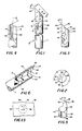
- a hole drilling tool 10 includes a shank end portion 11 and a cutting end portion or insert 12 of hard material, such as tungsten carbide or titanium carbide, joined in a conventional manner.
- the tool 10 includes a longitudinally extending V-shaped flute or groove 14, which is defined by two planar side surfaces 16, 18.
- the planar side surfaces 16, 18 intersect such that a portion of the intersection coincides with the axis 0-0 of the tool 10 at an obtuse angle A, as seen in Fig. 2, and extend radially outward from the intersection to a generally semi-cylindrical outer surface 20 of the tool 10.
- the side surface 18 tapers in the manner shown most clearly in Figs. 1 and 3.
- the side surface 16 preferably does not taper.
- the tool 10 has a planar end surface 22 whose shape is defined by the peripheral surfaces 16, 18, 20 of the tool.
- the planar end surface 22 defines an angle of inclination B to a horizontal plane orthogonal to the axis 0-0 of the tool 10, as shown in Fig. 1.
- the planar end surface 22 is inclined at the angle B to the horizontal plane so that it is shaped as an ellipse having one portion defined by the side surfaces 16, 18, removed to form the flute 14, as best seen in Fig. 5.
- planar end surface 22 is disposed relative to the flute 14 so that the flute side surface 16, the outer surface 20, and the planar end surface 22 intersect at a common single end point 24 which, when the tool 10 is rotated in a counter-clockwise direction as seen in Fig. 2, leads the lowest point 26 of the planar end surface 22 by an obtuse angle C less than 180°.
- the planar end surface 22 intersects the leading flute side surface 16 adjacent the single end point 24 at an acute angle D, as shown in Fig. 4, to form a first cutting edge 28.
- the flute side surface 16 intersects the outer surface 20 at a 90° angle, as shown in Fig. 2, to form a second cutting edge 30, which intersects the first cutting edge 28 at an acute angle E at the single end point 24, as shown in Fig. 3.
- the planar end surface 22 intersects the outer surface 20 to form a third edge 32 which is curved and extends from the single end point 24 and intersects the first cutting edge 28 at an acute angle F, as shown in Fig. 5.
- Two axially-extending segments 34, 35 of the outer semi-cylindrical surface 20 are slightly recessed from the surface 20 to provide radial clearance at these portions, typically in the order of 0.0735 mm (.003 inches), and to define three spaced-apart wearstrips 38, 40, 42, extending the length of the cutting portion 12 of the tool 10, extending the length of the cutting portion 12 of the tool 10, which serve as axial guides for the tool 10 when it is used for drilling deep holes.
- These radial relief segments 34, 36 may be formed by grinding axially-extending flat portions, as shown in Fig. 7a, or alternately may be cam ground to provide radial relief segments 34, 36 of semi-cylindrical shape.
- radial clearance is provided by a transition segment 44, of the outer surface 20 adjacent the flute side surface 18, to provide a gradual transition of radial compressive stresses as the final wearstrip 42 rotates within the hole formed in the composite material.
- This segment 44 is typically formed as a flat portion extending over approximately 5° of the outer surface 20 to provide approximately 0.0762 mm (.003 inches) clearance at the intersection of the flute side surface 18 and the wearstrip 42, as shown in Fig. 9.
- the angle A, at which the two flute side surfaces 16, 18 intersect is approximately 120°.
- the three wearstrips 38, 40, 42 extend approximately 235° of the outer surface 20. It is desirable that the cross-sectional area of the passage formed by the flute side surfaces 16, 18 and the side of the hole being drilled, which is proportional to the angle A, be relatively large to effect rapid and efficient removal of the composite chips during the hole forming operation. However, it is equally desirable that the three wearstrips 38, 40, 42, extend over a large portion of the outer surface 20 to effectively guide the tool 10. Both of these desired conditions are obtained by forming the flute side surfaces 16, 18 to intersect the angle A in the range of 110° to 130°.
- the angle C is made as large as possible, but less than 180° in order to provide a rotational clearance for the cutting edge 28.
- a preferred range for the angle C is 150° to 165°.
- the region of the tool at which the single end point 24 is defined is defined.
- angles E and D angle F is set, for the most part, by a determination of angles E and D
- angle F is set, for the most part, by a determination of angles E and D
- the optimum range of values for the angles E and D depends on the factors noted, the minimum value for these angles is largely determined by the characteristics of the tool 10. For example, breakage and wear at the single end point and heat conduction away from the single end point are factors to consider.
- the maximum value for these angles is largely determined by the characteristics of the composite. For example, undersizing, fraying and mushrooming are factors to consider.
- the single end point 24 will be more quickly worn down and more likely to break, and less heat will be conducted away from the single end point 24 through the tool 10. As these angles are increased, undersizing, fraying and mushrooming are more apt to appear. Also, all three of the wearstrips 38, 40, 42 will not enter the hole to serve as axial guides therein until the hole being formed is relatively deep.
- the minimum angle E of the tool 10 for drilling relatively deep holes in a composite i.e., holes where all three wearstrips enter the hole and serve a guide function, with a minimum risk of breakage, an acceptable amount of wear and an acceptable degree of heat transfer is preferably at least 20°.
- the corresponding minimum angle D is preferably at least 15°.
- the maximum angle E, from the standpoint of hole quality is preferably no more than 65°.
- the corresponding maximum angle D is preferably no more than 25°. Beyond these limits, the results obtained as to the tool and hole quality have been found to be unsatisfactory.
- the tool 10 having an angle E of 45° formed a hole of excellent quality, with virtually no fuzzing or delamination.
- the tool 10 having an angle E of 65° formed a hole which also appeared to be of excellent quality, when viewed by the naked eye. However, when viewed under a magnifier, some fuzzing around the edge of the hole, as well as delamination extending approximately 0.38 mm (.015 inch) beyond the edge of the hole, was evident.
- the tool 10 having an angle E of 80° formed a hole of lesser quality than the holes noted above in which fuzzing around the edge of the hole was observable to the naked eye. Also, delamination extended approximately 1.016 mm (.04 inch) beyond the edge of the hole.
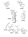
- Figs. 9-12 show a tool 10' for generating holes in composites of at least two materials having different moduli of elasticity, which has a single end point 24', three wearstrips 38', 40', 42', and a transition segment 44' for producing accurate holes with clean sides and edges.
- the two flute side surfaces 16', 18' extend radially inward from the outer surface 20' to a semi-cylindrical inner surface 46, which defines an axially-extending center bore of the tool 10' for receiving an uncut "core" portion of the composite when the tool 10' is used to generate a hole by the trepanning method.
- This embodiment of the invention can be used to quickly and accurately generate extremely large diameter holes in composites of the type described herein.
- the flute side surface 16' intersects the outer semi-cylindrical surface 20' at an acute angle H, as shown in Fig. 10, rather than at a right angle as in the case of the embodiment of Fig. 1.
- the flute side surface 16' must still intersect the planar end surface 22' at an acute angle D', as shown in Fig. 12.
- neither the cutting end surface, nor the surfaces defining the flute 14 are required to be planar surfaces, so long as the end surface intersects the leading flute side adjacent the single end point at an acute angle to form a first cutting edge, the leading flute side intersects the outer semi-cylindrical surface adjacent the single end point at an acute angle as well to form a second cutting edge, which intersects the first cutting edge at an acute angle adjacent the single end point, and the end surface intersects the outer surface to form a third edge which intersects the first and second cutting edges at respective acute angles.
- the flute 14 must extend radially inward to at least the axis of the tool. In the embodiment of Figs. 9-12, the flute 14' actually extends beyond the axis of the tool because of the space defined by the inner surface 46.
- transition segment 44' of the outer surface 20 can be a curved surface, rather than a flat surface, so long as it provides a gradual transition of radial compressive stresses in the composite during the rotation of the tool during a hole forming operation.
- the tool described herein can be used to generate holes in a wide variety of composites having one material which has significantly higher elasticity and/or tensile strength than other materials in the composite.
- this tool can be used to quickly and accurately drill high quality holes in a honeycomb structure of paper or other fiberous material impregnated with an epoxy resin and having a thin outer layer or skin of metal such as aluminum.
- a composite 50 is schematically illustrated in which a hole 52 is to be drilled.
- the hole 52 is to have a circumferential surface 54 and a central axis 0-0 (which coincides with the axis 0-0 of the tool 10).
- the tool 10 is used to generate the hole 52, it is rotated about its axis 0-0 in a counter-clockwise direction, as seen in Fig. 2, and moved in an axial direction to engage the cutting single end point 24 with the composite at point 56 on the circumferential surface 54.
- the tool 10 is guided within a conventional hardened guide bushing (not shown), which is well known to the art.
- the sharp cutting single end point 24 at the intersection of the first and second cutting edges 28, 30 first engages the composite to cleanly cut the outermostfibers atthe point 56 and commence successive penetration of parallel transverse planes of the composite in the direction of the axis 0-0 and about the circumferential surface 54.
- the single end point 24 cuts and penetrates the composite, the portions of the cutting edges 28 and 30 immediately adjacent the single end point 24 cut the composite material along 54 and 58, respectively.
- the first cutting edge 28 progressively engages the composite along, what can be considered a revolving radius 58, starting at the point 56, to cut chips therefrom which are axially directed through the flute 14.
- the three wearstrips 38, 40, 42 guide the tool within that portion of the hole previously cut so that the cutting single end point 24 produces a straight hole in the composite.
- the transition segment 44 prevents stretching or additional cutting of the more elastic component material of the composite by the tool edge formed by the outer surface 20 and the flute side 18, and thus contributes significantly to the hole quality, particularly at the hole entrance and exit.
Landscapes
- Engineering & Computer Science (AREA)
- Mechanical Engineering (AREA)
- Life Sciences & Earth Sciences (AREA)
- Forests & Forestry (AREA)
- Drilling Tools (AREA)
Claims (14)
und daß während eines Tiefbohrvorganges die Nutzstreifensegmente (38, 40, 42) der Außenfläche dazu dienen, das Werkzeug (10) innerhalb der zu bildenden Bohrung führen.
Applications Claiming Priority (2)
| Application Number | Priority Date | Filing Date | Title |
|---|---|---|---|
| US166868 | 1980-07-07 | ||
| US06/166,868 US4338050A (en) | 1980-07-07 | 1980-07-07 | Method and tool for generating holes in composite materials |
Publications (3)
| Publication Number | Publication Date |
|---|---|
| EP0043771A2 EP0043771A2 (de) | 1982-01-13 |
| EP0043771A3 EP0043771A3 (en) | 1982-03-31 |
| EP0043771B1 true EP0043771B1 (de) | 1987-04-15 |
Family
ID=22605006
Family Applications (1)
| Application Number | Title | Priority Date | Filing Date |
|---|---|---|---|
| EP81401069A Expired EP0043771B1 (de) | 1980-07-07 | 1981-07-03 | Werkzeug zum Erzeugen von Löchern in Faserwerkstoffen |
Country Status (3)
| Country | Link |
|---|---|
| US (1) | US4338050A (de) |
| EP (1) | EP0043771B1 (de) |
| DE (1) | DE3176109D1 (de) |
Families Citing this family (29)
| Publication number | Priority date | Publication date | Assignee | Title |
|---|---|---|---|---|
| IT1127526B (it) * | 1980-08-01 | 1986-05-21 | Aeritalia Spa | Punta da trapano per eseguire fori in laminati di materiale composito di fibre/resina |
| US4475850A (en) * | 1981-08-16 | 1984-10-09 | Penoza Frank J | Split helix router bit |
| US4449865A (en) * | 1981-11-18 | 1984-05-22 | The Boeing Company | Method and tool for generating countersunk holes in composite materials |
| US4725171A (en) * | 1984-03-02 | 1988-02-16 | Detorre Robert P | Drill for aramid composites |
| SE441807B (sv) * | 1984-04-09 | 1985-11-11 | Santrade Ltd | Borr for borrning av arbetsstycken, foretredesvis av kompositmaterial |
| SE456655B (sv) * | 1985-03-07 | 1988-10-24 | Sandvik Ab | Borr foer upptagning av haal i en komposit |
| US4909678A (en) * | 1987-08-31 | 1990-03-20 | Ushio Co, Ltd. | Boring apparatus for a laminated plate and boring cutter |
| FR2656554A1 (fr) * | 1989-12-28 | 1991-07-05 | Snecma | Outil de percage de precision pour materiaux composites. |
| SE500139C2 (sv) * | 1992-05-06 | 1994-04-25 | Strukturteknologier I Stockhol | Metod att bearbeta och forma en genomgående öppning i ett fiberarmerat kompositmaterial med ett slipverktyg |
| SE507954C2 (sv) * | 1992-09-15 | 1998-08-03 | Sandvik Ab | Metod att bearbeta kompositer |
| SE9203493L (sv) * | 1992-11-19 | 1994-05-20 | Strukturteknologier I Stockhol | Metod för håltagning i fiberarmerade kompositmaterial och verktyg för genomförande av metoden |
| SE504312C2 (sv) * | 1994-10-28 | 1997-01-13 | Sandvik Ab | Metod att bearbeta kompositer |
| US6007281A (en) * | 1998-04-09 | 1999-12-28 | Novator Ab | Method of producing holes in fiber reinforced composites using a tool with a cutting head having an enlarged diameter and reduced height |
| US6030156A (en) * | 1998-04-17 | 2000-02-29 | Andronica; Randall | Drill and sharpening fixture |
| US5967707A (en) * | 1998-07-29 | 1999-10-19 | Diesel Technology Company | Short-hole drill bit |
| US6220795B1 (en) | 1999-04-05 | 2001-04-24 | Vermont Indexable Tooling, Inc. | Spotting drill and milling cutter |
| US6908266B1 (en) * | 2000-10-31 | 2005-06-21 | Eastman Kodak Company | Apparatus for forming a microlens array mold |
| US6846137B1 (en) * | 2000-10-31 | 2005-01-25 | Eastman Kodak Company | Apparatus for forming a microlens mold |
| US6491481B1 (en) * | 2000-10-31 | 2002-12-10 | Eastman Kodak Company | Method of making a precision microlens mold and a microlens mold |
| US6773211B2 (en) | 2001-05-18 | 2004-08-10 | Novator Ab | Orbital drilling cutting tool |
| JP4740842B2 (ja) * | 2004-03-26 | 2011-08-03 | 株式会社牧野フライス製作所 | 切削加工方法及び装置 |
| TWI284071B (en) * | 2004-09-23 | 2007-07-21 | Asia Optical Co Inc | A gear cutter |
| CN100423875C (zh) * | 2004-11-25 | 2008-10-08 | 亚洲光学股份有限公司 | 齿轮型刀 |
| US8021085B1 (en) * | 2007-02-23 | 2011-09-20 | Lance Nelson | Engraving tool with a very strong cutter tip to reduce breakage |
| JP4564562B2 (ja) * | 2008-11-28 | 2010-10-20 | ユニオンツール株式会社 | 穴明け工具 |
| DE112009005271T5 (de) | 2009-09-23 | 2013-01-10 | Osg Corp. | Schneidwerkzeug |
| US20130164088A1 (en) * | 2011-12-21 | 2013-06-27 | Peter Diamantis | Drill for composite materials |
| DE102017103592A1 (de) * | 2017-02-22 | 2018-08-23 | Gühring KG | Bohrwerkzeug für Faserplatten |
| JP7317371B2 (ja) | 2020-01-29 | 2023-07-31 | 株式会社オカモト | 孔あけ具 |
Citations (1)
| Publication number | Priority date | Publication date | Assignee | Title |
|---|---|---|---|---|
| EP0007512A1 (de) * | 1978-08-01 | 1980-02-06 | Stellram S.A. | Bohrer mit Wendeplatten |
Family Cites Families (11)
| Publication number | Priority date | Publication date | Assignee | Title |
|---|---|---|---|---|
| DE262125C (de) * | ||||
| US1789793A (en) * | 1929-05-18 | 1931-01-20 | Ernest O Wedhorn | Router cutter |
| US1907880A (en) * | 1930-06-19 | 1933-05-09 | Royle Vernon | Routing tool |
| US2718689A (en) * | 1950-09-28 | 1955-09-27 | Roger S Mason | Routing |
| US2792862A (en) * | 1955-05-02 | 1957-05-21 | Cleveland Twist Drill Co | Acoustical tile drill |
| US3014386A (en) * | 1957-09-03 | 1961-12-26 | United Greenfield Corp | Drill |
| US3120766A (en) * | 1961-04-14 | 1964-02-11 | Zagar Inc | Gun type drilling means |
| US3260139A (en) * | 1963-08-07 | 1966-07-12 | Sanborn Frank Eugene | Self-clearing drill |
| US3227013A (en) * | 1963-10-24 | 1966-01-04 | Zimmermann Lukas | Trepanning tools |
| SU568489A1 (ru) * | 1976-04-28 | 1977-08-15 | Ордена Трудового Красного Знамени Институт Проблем Материаловедения Ан Украинской Сср | Устройство дл стапелировани плоских деталей |
| NL182867C (nl) * | 1977-04-04 | 1988-06-01 | Yamada Akio | Frees. |
-
1980
- 1980-07-07 US US06/166,868 patent/US4338050A/en not_active Expired - Lifetime
-
1981
- 1981-07-03 EP EP81401069A patent/EP0043771B1/de not_active Expired
- 1981-07-03 DE DE8181401069T patent/DE3176109D1/de not_active Expired
Patent Citations (1)
| Publication number | Priority date | Publication date | Assignee | Title |
|---|---|---|---|---|
| EP0007512A1 (de) * | 1978-08-01 | 1980-02-06 | Stellram S.A. | Bohrer mit Wendeplatten |
Non-Patent Citations (2)
| Title |
|---|
| Fachkunde für metallverarbeitende Berufe, 9. Auflage, Verlag Willing & Co. Wuppertal, page 221; Hoffmann Katalog, 9 (1977) München, pages 101,102 * |
| Soviet Inventions Illustrated Week C22, 9 July 1980 Section P54 * |
Also Published As
| Publication number | Publication date |
|---|---|
| EP0043771A3 (en) | 1982-03-31 |
| DE3176109D1 (en) | 1987-05-21 |
| EP0043771A2 (de) | 1982-01-13 |
| US4338050A (en) | 1982-07-06 |
Similar Documents
| Publication | Publication Date | Title |
|---|---|---|
| EP0043771B1 (de) | Werkzeug zum Erzeugen von Löchern in Faserwerkstoffen | |
| US4352610A (en) | Method and tool for generating holes in composite materials | |
| US4810136A (en) | Milling cutter for composite laminates | |
| US3779664A (en) | Drill with guide tip | |
| US7588396B2 (en) | End mill | |
| US6007281A (en) | Method of producing holes in fiber reinforced composites using a tool with a cutting head having an enlarged diameter and reduced height | |
| EP0761352B1 (de) | Walzgeschmiedeter Bohrer | |
| US4449865A (en) | Method and tool for generating countersunk holes in composite materials | |
| WO2009130821A1 (ja) | 深穴切削用スローアウェイチップ及び深穴切削用ドリルヘッド | |
| EP0332437B1 (de) | Bohrer | |
| US4789276A (en) | Twist drill for tough plastics | |
| US10525539B2 (en) | Compression milling cutter with indexable cutting inserts | |
| JP2699527B2 (ja) | ツイストドリル | |
| US4285620A (en) | Symmetrical spur point drill | |
| US4400119A (en) | Twist drill | |
| JPH02198708A (ja) | ニック付切削工具 | |
| EP0775560A2 (de) | Bohrer für die Holzbearbeitung | |
| JPS61270010A (ja) | 穴あけ工具 | |
| JPH02237712A (ja) | ツイストドリル | |
| JP2021088007A (ja) | ドリル | |
| CA1234001A (en) | Drill for generating a hole in a work piece | |
| EP0105935A1 (de) | Hohlbohrer und Verfahren zur Herstellung von Löchern in zusammengestelltem Material | |
| US4712952A (en) | Drill for generating of holes in a work piece | |
| JPH10151604A (ja) | 木工用ボーリング錐 | |
| JPH02237711A (ja) | ツイストドリル |
Legal Events
| Date | Code | Title | Description |
|---|---|---|---|
| PUAI | Public reference made under article 153(3) epc to a published international application that has entered the european phase |
Free format text: ORIGINAL CODE: 0009012 |
|
| AK | Designated contracting states |
Designated state(s): BE CH DE FR GB IT LI LU NL SE |
|
| PUAL | Search report despatched |
Free format text: ORIGINAL CODE: 0009013 |
|
| AK | Designated contracting states |
Designated state(s): BE CH DE FR GB IT LI LU NL SE |
|
| 17P | Request for examination filed |
Effective date: 19820812 |
|
| GRAA | (expected) grant |
Free format text: ORIGINAL CODE: 0009210 |
|
| AK | Designated contracting states |
Kind code of ref document: B1 Designated state(s): BE CH DE FR GB IT LI LU NL SE |
|
| PG25 | Lapsed in a contracting state [announced via postgrant information from national office to epo] |
Ref country code: NL Effective date: 19870415 Ref country code: LI Effective date: 19870415 Ref country code: CH Effective date: 19870415 Ref country code: BE Effective date: 19870415 |
|
| ITF | It: translation for a ep patent filed |
Owner name: BUGNION S.P.A. |
|
| PG25 | Lapsed in a contracting state [announced via postgrant information from national office to epo] |
Ref country code: SE Effective date: 19870430 |
|
| REF | Corresponds to: |
Ref document number: 3176109 Country of ref document: DE Date of ref document: 19870521 |
|
| ET | Fr: translation filed | ||
| PG25 | Lapsed in a contracting state [announced via postgrant information from national office to epo] |
Ref country code: LU Free format text: LAPSE BECAUSE OF NON-PAYMENT OF DUE FEES Effective date: 19870731 |
|
| REG | Reference to a national code |
Ref country code: CH Ref legal event code: PL |
|
| NLV1 | Nl: lapsed or annulled due to failure to fulfill the requirements of art. 29p and 29m of the patents act | ||
| PLBE | No opposition filed within time limit |
Free format text: ORIGINAL CODE: 0009261 |
|
| STAA | Information on the status of an ep patent application or granted ep patent |
Free format text: STATUS: NO OPPOSITION FILED WITHIN TIME LIMIT |
|
| 26N | No opposition filed | ||
| PGFP | Annual fee paid to national office [announced via postgrant information from national office to epo] |
Ref country code: GB Payment date: 19920617 Year of fee payment: 12 |
|
| PGFP | Annual fee paid to national office [announced via postgrant information from national office to epo] |
Ref country code: FR Payment date: 19920713 Year of fee payment: 12 |
|
| PGFP | Annual fee paid to national office [announced via postgrant information from national office to epo] |
Ref country code: DE Payment date: 19920730 Year of fee payment: 12 |
|
| ITTA | It: last paid annual fee | ||
| PG25 | Lapsed in a contracting state [announced via postgrant information from national office to epo] |
Ref country code: GB Effective date: 19930703 |
|
| GBPC | Gb: european patent ceased through non-payment of renewal fee |
Effective date: 19930703 |
|
| PG25 | Lapsed in a contracting state [announced via postgrant information from national office to epo] |
Ref country code: FR Effective date: 19940331 |
|
| PG25 | Lapsed in a contracting state [announced via postgrant information from national office to epo] |
Ref country code: DE Effective date: 19940401 |
|
| REG | Reference to a national code |
Ref country code: FR Ref legal event code: ST |