EP0043328B1 - Energy production installation comprising several fast neutron breeder nuclear reactors and an apparatus for charging and discharging fuel elements - Google Patents
Energy production installation comprising several fast neutron breeder nuclear reactors and an apparatus for charging and discharging fuel elements Download PDFInfo
- Publication number
- EP0043328B1 EP0043328B1 EP81401046A EP81401046A EP0043328B1 EP 0043328 B1 EP0043328 B1 EP 0043328B1 EP 81401046 A EP81401046 A EP 81401046A EP 81401046 A EP81401046 A EP 81401046A EP 0043328 B1 EP0043328 B1 EP 0043328B1
- Authority
- EP
- European Patent Office
- Prior art keywords
- ramp
- reactor
- enclosure
- ramps
- loading
- Prior art date
- Legal status (The legal status is an assumption and is not a legal conclusion. Google has not performed a legal analysis and makes no representation as to the accuracy of the status listed.)
- Expired
Links
Images


Classifications
-
- G—PHYSICS
- G21—NUCLEAR PHYSICS; NUCLEAR ENGINEERING
- G21C—NUCLEAR REACTORS
- G21C19/00—Arrangements for treating, for handling, or for facilitating the handling of, fuel or other materials which are used within the reactor, e.g. within its pressure vessel
- G21C19/32—Apparatus for removing radioactive objects or materials from the reactor discharge area, e.g. to a storage place; Apparatus for handling radioactive objects or materials within a storage place or removing them therefrom
-
- G—PHYSICS
- G21—NUCLEAR PHYSICS; NUCLEAR ENGINEERING
- G21C—NUCLEAR REACTORS
- G21C19/00—Arrangements for treating, for handling, or for facilitating the handling of, fuel or other materials which are used within the reactor, e.g. within its pressure vessel
- G21C19/20—Arrangements for introducing objects into the pressure vessel; Arrangements for handling objects within the pressure vessel; Arrangements for removing objects from the pressure vessel
-
- Y—GENERAL TAGGING OF NEW TECHNOLOGICAL DEVELOPMENTS; GENERAL TAGGING OF CROSS-SECTIONAL TECHNOLOGIES SPANNING OVER SEVERAL SECTIONS OF THE IPC; TECHNICAL SUBJECTS COVERED BY FORMER USPC CROSS-REFERENCE ART COLLECTIONS [XRACs] AND DIGESTS
- Y02—TECHNOLOGIES OR APPLICATIONS FOR MITIGATION OR ADAPTATION AGAINST CLIMATE CHANGE
- Y02E—REDUCTION OF GREENHOUSE GAS [GHG] EMISSIONS, RELATED TO ENERGY GENERATION, TRANSMISSION OR DISTRIBUTION
- Y02E30/00—Energy generation of nuclear origin
- Y02E30/30—Nuclear fission reactors
Definitions
- the invention relates to an energy production installation comprising several fast neutron nuclear reactors and a loading and unloading device allowing the passage of fuel assemblies between a primary loading and unloading ramp communicating with the vessel of a reactor. fast neutrons and a secondary ramp communicating with an assembly storage or loading area.
- the fuel assemblies constituting the core of the nuclear reactor arranged in the vessel thereof must be able to be replaced after a certain period of use in the reactor.
- These extraction and transfer means described in FR-A2267614 generally include a transfer machine disposed above the reactor vessel allowing the extraction of fuel assemblies from the core, their transfer and their deposition in a zone of the vessel. of the reactor into which an assembly transport ramp leads, called the primary ramp.
- This primary ramp allows the transport of assemblies from the reactor vessel to a transfer device called loading and unloading lock in which the assembly can be transferred into a second ramp called secondary ramp which communicates with a storage area for assemblies or with a loading area for these assemblies in means of transport or temporary storage.
- the assemblies are moved inside the primary and secondary ramps by traction devices such as winches.
- the loading and unloading lock contains a mobile ramp fixed to a turnstile allowing its rotation under the effect of motor means arranged at the top of the lock for its displacement by pivoting between a position where the mobile ramp is in the extension of the primary ramp and a position where this mobile ramp is located in the extension of the secondary ramp.
- the traction device is generally fixed on the turnstile and therefore follows the rotational movements of the mobile ramp.
- Certain loading and unloading airlocks comprise two mobile ramps, the simultaneous rotation of which allows each of these ramps to pass from a position in communication with the primary ramp to a position where it is in communication with the secondary ramp and vice versa.
- the loading and unloading airlock and the transfer devices associated with it are based on the reactor structure on which the vessel and the associated reactor installations are fixed.
- the periods of operation of this element are widely spaced over time since they correspond to the periods during which the reactor is stopped in order to refuel.
- the airlock is used not only for unloading irradiated assemblies but for recharging the reactor with new assemblies, the movement of these assemblies taking place from the storage area to the heart of the reactor via the secondary and primary ramps.
- the mechanical devices of the loading and unloading airlock are therefore brought to operate at extremely distant moments in time, so that one cannot be sure of the good functioning of these mechanical organs which have undergone a very long shutdown.
- the object of the invention is therefore to propose an energy production installation comprising several fast nuclear neutron reactors located on the same site, each comprising a vessel containing the core of the reactor immersed in coolant sodium, a structure supporting the tank, a primary ramp for loading and unloading the fuel assemblies of the core communicating with the reactor vessel and a secondary ramp communicating with a storage or loading area for the assemblies, these primary and secondary ramps carried by the structure being provided at their ends of insulation means, the installation comprising a device for loading and unloading of fuel assemblies consisting of an airlock resting on the structure of a reactor, inside which are fixed a transfer means constituted by at least one movable ramp between a position in communication with the primary ramp and a position in communication with the secondary ramp by means of motors and at least one device connected to the mobile ramp for moving the assemblies inside the ramps, this installation having to make it possible to reduce the cost of construction of the nuclear reactors grouped on the same site while ensuring more frequent service of the mechanical elements of the loading and unloading device on any one of the nuclear
- the loading and unloading device is removable as a whole, the airlock being constituted by a demountable enclosure, transportable and comprising connection and isolation means, at the level of openings made in its wall, for its communication with the primary and secondary ramps of a reactor at the ends of these ramps provided with isolation means.
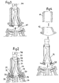
- Figure 1 we see the structure 1 of a nuclear reactor carrying a tank 2 inside which are arranged assemblies 3 constituting the core of the nuclear reactor.
- a transfer machine 5 which can be moved in rotation to occupy any position above the network of fuel assemblies by means of rotary caps 7 and 8 ensures the transfer of the assemblies 3 first to position 3a by means of telescopic movements of the transfer machine then in posibion 3b by rotation of the transfer machine then lowering of the assembly vertically by telescopic movements.
- the assembly can be tilted in a ramp 10 called primary ramp which opens at its upper part in an airlock 11 inside which also a ramp 12 communicates the airlock with a storage area 14.
- the isolation of the airlock from ramps 10 and 12 can be carried out using valves 16 and 17.
- a ramp movable in rotation 15 integral with a turntable 18 disposed at the upper part of the airlock 11 can be placed successively in position 15a in communication with the primary ramp and in position 15b in communication with the secondary ramp.
- An assembly 3 can be brought inside this mobile ramp from the primary ramp or from the secondary ramp thanks to a winch 19 surmounting the airlock 11 called the loading and unloading airlock.
- the displacement of the assemblies inside the ramps 10 and 12 and inside the airlock can be carried out only by the winch 19 or by the winch 19 and other winches arranged at the entrance to the primary and secondary ramps.
- the assembly can be taken care of after tilting in the vertical position, by a transfer machine 20 which can move the assembly 3 in the vertical direction in one direction and in the other, which allows to place this assembly 3 in any position inside the barrel tower storage space 21 arranged inside the storage area 14.
- new assemblies arranged in the storage zone can be removed by the transfer machine 20 and deposited in the part of this zone which makes it possible to tilt them in the secondary ramp 12 for the introduction of these assemblies into the reactor vessel. via the loading and unloading airlock 11.
- the loading and unloading lock is permanently placed on the structure 1 of the nuclear reactor which carries the ramps 10 and 12 opening into the lock.
- the large airlock forms a complex and bulky assembly covered by the elements 23 of great thickness for the protection of the neighboring areas of the airlock against radiation.
- Such a device according to the invention comprises a sealed metallic enclosure 25 comprising two openings 26 and 27 corresponding respectively to the primary and secondary ramps 28 and 29 of the reactor on which the removable airlock according to the invention is placed.
- Valves 30 and 31 can close these openings 26 and 27 located on the enclosure, respectively while valves 32 and 33 close the ends of the primary and secondary ramps respectively, these ramps communicating with the interior of the reactor and the storage area.
- junction flanges arranged between the valves 30 and 32 and 31 and 33 respectively make it possible to fix the removable airlock constituted by the sealed enclosure 25 on the primary and secondary ramps of a nuclear reactor.
- the enclosure 25 is covered by elements 34 providing insulation against radiation, from the outside of the airlock relative to the inside.
- a mobile ramp 35 is placed inside the airlock on a rotating element 36 which makes it possible to put this ramp in communication either with the primary ramp 28 or with the secondary ramp 29.
- a winch 37 which allows the displacement of the fuel assemblies inside the ramps either in the direction of the ascent or in the direction of the descent.
- FIG. 3 it can be seen that when the uncoupling between the removable airlock and the reactor has been carried out by dismantling the assembly flange disposed between the isolation valves, the removable airlock can be raised by an overhead crane, gripping elements 38 being provided at the upper part of the airlock.
- FIG 4 there is shown a removable airlock identical to the airlock shown in Figures 2 and 3 but whose insulation elements against radiation are made up of two separate parts 41 and 42 which can be put in place on the enclosure 25 or on the contrary separated from it independently of one another.
- the whole of the airlock and its radiation insulating elements is of very great weight, for example 400 to 500 tonnes and it may be difficult to have sufficient lifting means to lift the entire airlock. above the reactor and to move it to a new service position above another reactor.
- FIGS. 5 and 6 another embodiment of the enclosure of the removable airlock has been shown, this enclosure 45 being constituted by a cylinder comprising two openings 46 and 47 at its lower part and an assembly 48 for moving the mobile ramp 50 and a winch 49 at its upper part.
- this assembly can be disconnected from the primary and secondary ramps of the reactor and extracted from the protective structure 51 constituted by a very thick cylinder of insulating material placed at a fixed position on the reactor and whose the right section corresponds to the right section of the enclosure.
- a complementary protective plate 52 is then placed on the upper part of the cylinder 51 to completely isolate the interior of the reactor.
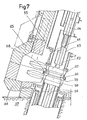
- FIGS 7 and 8 show in more detail all of the means of connection and isolation of the airlock and the secondary ramp of the reactor.
- connection and isolation means are placed at the level of the openings of the enclosure 55 allowing the latter to be placed in communication with the primary ramp or with the secondary ramp.
- FIGS. 7 and 8 show the connection and isolation devices allowing the enclosure to be placed in communication with the secondary ramp 56 secured to the structure 57 of the reactor.
- the ramp 56 is integral with an assembly comprising an isolation valve 58 and a fixing flange 59 carrying centering pins 60.
- the enclosure 55 carries at its lower part, by means of a bellows seal 61, an isolation valve 62 and a section of ramp 63 fixed relative to the enclosure 55, apart from slight displacements or deflections of this ramp 63 relative to the enclosure 55, obtained by deformation of the bellows seal 61 placed in the extension of the ramp 56.
- the mobile ramp 64 can then be placed in the extension of the ramp 63 by tilting.
- the ramp 64 has been shown in its position where it is in communication with the secondary ramp 56 and in FIG. 8, the mobile ramp 64 has been shown in a position where the mobile ramp and the fixed ramp are not more in line with each other.
- the mobile ramp is movable by tilting and rotation between its position shown in FIG. 7 and a position where the mobile ramp 64 is in the extension of a section of fixed ramp not shown allowing the junction with the primary ramp of the reactor.
- the enclosure 55 is surrounded by radiation protection elements 65 which come during the installation of the airlock on the reactor in the extension of protection elements 66 integral with the structure 57 of the reactor, to constitute with these this protection around the entire perimeter of the airlock.
- a flange 67 is also secured to the valve 62 at its lower end coming into position opposite the flange 59 secured to the valve 58 disposed on the fixed support structure of the secondary rail on the reactor.
- the flange 67 has holes allowing the positioning of the centering pins 60 during docking of the airlock on the reactor.
- the removable airlock according to the invention having to be used on several reactors, for example arranged on the same site, it is necessary to be able to adapt the junction device of this airlock to slight dimensional differences which may exist between two reactors as regards the tilt or position of the primary and secondary ramps. This is the reason why the ramp 63 integral with the enclosure 55 is fixed thereto by means of a bellows seal 61 which allows slight displacements or deflections.
- the centering pins 60 of the flange 59 can always be made to coincide with the holes in the flange 67.
- the airlock is fixed by tightening the flanges 59 and 67 and the corresponding flanges at the primary ramp.
- the ramps 59 and 67 have a number of holes 68 in which are introduced screws which are fixed by nuts.
- the mobile ramp 64 being placed by tilting relative to the ramp 63 in the extension of the latter thanks to a stop stopping its travel at the desired location, the continuity of the ramps is ensured between the mobile ramp and the primary ramps and secondary of the reactor.
- a slight angular variation in the displacement of the mobile ramp makes it possible to absorb slight deviations coming from deviations between the inclinations or the centers of the ramps from one reactor to another.
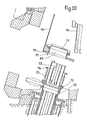
- FIGS. 9 and 10 another embodiment of the junction and isolation device between the enclosure 55 and the secondary ramp 56 is seen, the enclosure 55 carrying at its opening 69 a flange 70 carrying pins centering 71.
- the upper end of the ramp 56 carries a valve 72 itself extended by a portion of the ramp 73, however a flange 74 having holes corresponding to the centering pins 71 is fixed to the valve 72 by means of a bellows seal 75.
- An internal valve 77 enables the opening 69 to be closed when the airlock is isolated from the external environment, for its transport for example.
- the main advantages of the device according to the invention are that it makes it possible to use only one airlock containing the mobile devices for loading and unloading assemblies for a set of reactors, which saves on costs. construction of the nuclear reactor, to operate the mechanisms associated with the airlock more frequently and to allow easy maintenance of the airlock during the operation of the reactor.
- the shape of the enclosure constituting the airlock is not limited to the forms which have been described and shown, that the mode of fixing and isolation of the airlock can be different from the modes of fixing and isolation. which have been described and that the achievement of protection against radiation can be obtained in a different way from the particular modes described.
- the loading and unloading device according to the invention can be used for all fast neutron nuclear reactors using an airlock passing the fuel elements from a primary rail communicating with the reactor vessel to a secondary rail communicating with a point storage or loading of fuel assemblies.
Description
L'invention concerne une installation de production d'énergie comportant plusieurs réacteurs nucléaires à neutrons rapides et un dispositif de chargement et de déchargement permettant le passage des assemblages combustibles entre une rampe primaire de chargement et de déchargement communiquant avec la cuve d'un réacteur à neutrons rapides et une rampe secondaire communiquant avec une zone de stockage ou de chargement des assemblages.The invention relates to an energy production installation comprising several fast neutron nuclear reactors and a loading and unloading device allowing the passage of fuel assemblies between a primary loading and unloading ramp communicating with the vessel of a reactor. fast neutrons and a secondary ramp communicating with an assembly storage or loading area.
Dans le cas des réacteurs nucléaires à neutrons rapides, les assemblages combustibles constituant le coeur du réacteur nucléaire disposés dans la cuve de celui-ci doivent pouvoir être remplacés après un certain temps d'utilisation dans le réacteur.In the case of fast neutron nuclear reactors, the fuel assemblies constituting the core of the nuclear reactor arranged in the vessel thereof must be able to be replaced after a certain period of use in the reactor.
Dans ce type de réacteur, on dispose donc de moyens permettant d'extraire les assemblages irradiés du coeur du réacteur puis de la cuve de celui-ci pour les transférer dans une zone de stockage et de décontamination ou dans un moyen de transport et de stockage provisoire.In this type of reactor, there are therefore means making it possible to extract the irradiated assemblies from the core of the reactor and then from the vessel thereof to transfer them to a storage and decontamination zone or to a means of transport and storage. provisional.
Ces moyens d'extraction et de transfert décrits dans le FR-A2267614 comportent généralement une machine de transfert disposée au-dessus de la cuve du réacteur permettant l'extraction des assemblages combustibles du coeur, leur transfert et leur dépôt dans une zone de la cuve du réacteur dans laquelle débouche une rampe de transport des assemblages appelée rampe primaire. Cette rampe primaire permet le transport des assemblages depuis la cuve du réacteur jusqu'à un dispositif de transfert appelé sas de chargement et de déchargement dans lequel l'assemblage peut être transféré dans une seconde rampe appelée rampe secondaire qui communique avec une zone de stockage des assemblages ou avec une zone de chargement de ces assemblages dans des moyens de transport ou de stockage temporaire.These extraction and transfer means described in FR-A2267614 generally include a transfer machine disposed above the reactor vessel allowing the extraction of fuel assemblies from the core, their transfer and their deposition in a zone of the vessel. of the reactor into which an assembly transport ramp leads, called the primary ramp. This primary ramp allows the transport of assemblies from the reactor vessel to a transfer device called loading and unloading lock in which the assembly can be transferred into a second ramp called secondary ramp which communicates with a storage area for assemblies or with a loading area for these assemblies in means of transport or temporary storage.
Les assemblages sont déplacés à l'intérieur des rampes primaire et secondaire par des dispositifs de traction tels que des treuils.The assemblies are moved inside the primary and secondary ramps by traction devices such as winches.
Le sas de chargement et de déchargement renferme une rampe mobile fixée à un tourniquet permettant sa mise en rotation sous l'effet de moyens moteurs disposés à la partie supérieure du sas pour son déplacement par pivotement entre une position où la rampe mobile se trouve dans le prolongement de la rampe primaire et une position où cette rampe mobile se trouve dans le prolongement de la rampe secondaire.The loading and unloading lock contains a mobile ramp fixed to a turnstile allowing its rotation under the effect of motor means arranged at the top of the lock for its displacement by pivoting between a position where the mobile ramp is in the extension of the primary ramp and a position where this mobile ramp is located in the extension of the secondary ramp.
Le dispositif de traction est généralement fixé sur le tourniquet et suit donc les mouvements de rotation de la rampe mobile.The traction device is generally fixed on the turnstile and therefore follows the rotational movements of the mobile ramp.
D'autres dispositifs de déplacement des assemblages à l'intérieur des rampes primaire et secondaire peuvent également être fixés à ces rampes pour le déplacement des assemblages pendant une partie de leur transport entre la cuve et le sas de chargement ou entre le sas de chargement et de déchargement et la zone de stockage.Other devices for moving the assemblies inside the primary and secondary ramps can also be fixed to these ramps for moving the assemblies during part of their transport between the tank and the loading airlock or between the loading airlock and unloading and storage area.
Certains sas de chargement et de déchargement comportent deux rampes mobiles dont la mise en rotation simultanée permet de faire passer chacune de ces rampes d'une position en communication avec la rampe primaire à une position où elle est en communication avec la rampe secondaire et inversement.Certain loading and unloading airlocks comprise two mobile ramps, the simultaneous rotation of which allows each of these ramps to pass from a position in communication with the primary ramp to a position where it is in communication with the secondary ramp and vice versa.
Des assemblages étant amenés par les dispositifs de traction à l'intérieur de la rampe mobile, on peut ainsi faire passer ces assemblages de la rampe primaire à la rampe secondaire.Assemblies being brought by the traction devices inside the movable ramp, it is thus possible to pass these assemblies from the primary ramp to the secondary ramp.
Le sas de chargement et de déchargement et les dispositifs de transfert qui lui sont associés reposent sur la structure du réacteur sur laquelle sont fixées la cuve et les installations annexes du réacteur.The loading and unloading airlock and the transfer devices associated with it are based on the reactor structure on which the vessel and the associated reactor installations are fixed.
Ce sas est extrêmement encombrant et le coût de construction de cet élément intervient pour une part relativement importante dans le coût de construction du réacteur.This airlock is extremely bulky and the cost of construction of this element accounts for a relatively large part in the cost of construction of the reactor.
Par ailleurs, les périodes de fonctionnement de cet élément sont très espacées dans le temps puisqu'elles correspondent aux périodes pendant lesquelles on arrête le réacteur pour effectuer le rechargement en combustible. Le sas sert en effet non seulement au déchargement des assemblages irradiés mais au rechargement du réacteur en assemblages neufs, le mouvement de ces assemblages se faisant depuis la zone de stockage jusqu'au coeur du réacteur par l'intermédiaire des rampes secondaire et primaire.Furthermore, the periods of operation of this element are widely spaced over time since they correspond to the periods during which the reactor is stopped in order to refuel. The airlock is used not only for unloading irradiated assemblies but for recharging the reactor with new assemblies, the movement of these assemblies taking place from the storage area to the heart of the reactor via the secondary and primary ramps.
Les dispositifs mécaniques du sas de chargement et de déchargement sont donc amenés à fonctionner à des moments extrêmement éloignés dans le temps, si bien qu'on ne peut être sûr du bon fonctionnement de ces organes mécaniques qui ont subi un arrêt de très longue durée.The mechanical devices of the loading and unloading airlock are therefore brought to operate at extremely distant moments in time, so that one cannot be sure of the good functioning of these mechanical organs which have undergone a very long shutdown.
La tendance actuelle dans la construction des réacteurs nucléaires à neutrons rapides est de grouper ces réacteurs, par exemple par deux ou quatre unités, sur un même site pour réduire certains investissements par la mise en commun de certains organes de ces réacteurs.The current trend in the construction of fast neutron nuclear reactors is to group these reactors, for example by two or four units, on the same site to reduce certain investments by pooling certain parts of these reactors.
On n'a cependant jamais pensé à utiliser un même sas de chargement et de déchargement pour un ensemble comportant plusieurs réacteurs.However, we have never thought of using the same loading and unloading airlock for an assembly comprising several reactors.
Le but de l'invention est donc de proposer une installation de production d'énergie comportant plusieurs réacteurs nucléaires à neutrons rapides implantés sur un même site comportant chacun une cuve renfermant le coeur du réacteur immergé dans du sodium liquide de refroidissement, une structure supportant la cuve, une rampe primaire de chargement et de déchargement des assemblages combustibles du coeur communiquant avec la cuve du réacteur et une rampe secondaire communiquant avec une zone de stockage ou de chargement des assemblages, ces rampes primaire et secondaire portées par la structure étant munies à leurs extrémités de moyens d'isolation, l'installation comprenant un dispositif de chargement et de déchargement d'assemblages combustibles constitué par un sas reposant sur la structure d'un réacteur, à l'intérieur duquel sont fixés un moyen de transfert constitué par au moins une rampe mobile entre une position en communication avec la rampe primaire et une position en communication avec la rampe secondaire grâce à des moyens moteurs et au moins un dispositif relié à la rampe mobile de déplacement des assemblages à l'intérieur des rampes, cette installation devant permettre de réduire le coût de construction des réacteurs nucléaires groupés sur le même site tout en assurant un service plus fréquent des éléments mécaniques du dispositif de chargement et de déchargement sur l'un quelconque des réacteurs nucléaires, tout en autorisant également une maintenance aisée du sas pendant le fonctionnement du réacteur.The object of the invention is therefore to propose an energy production installation comprising several fast nuclear neutron reactors located on the same site, each comprising a vessel containing the core of the reactor immersed in coolant sodium, a structure supporting the tank, a primary ramp for loading and unloading the fuel assemblies of the core communicating with the reactor vessel and a secondary ramp communicating with a storage or loading area for the assemblies, these primary and secondary ramps carried by the structure being provided at their ends of insulation means, the installation comprising a device for loading and unloading of fuel assemblies consisting of an airlock resting on the structure of a reactor, inside which are fixed a transfer means constituted by at least one movable ramp between a position in communication with the primary ramp and a position in communication with the secondary ramp by means of motors and at least one device connected to the mobile ramp for moving the assemblies inside the ramps, this installation having to make it possible to reduce the cost of construction of the nuclear reactors grouped on the same site while ensuring more frequent service of the mechanical elements of the loading and unloading device on any one of the nuclear reactors, while also allowing easy maintenance of the airlock during the operation of the reactor.
Dans ce but, le dispositif de chargement et de déchargement suivant l'invention est amovible dans son ensemble, le sas étant constitué par une enceinte démontable, transportable et comportant des moyens de liaison et d'isolement, au niveau d'ouvertures pratiquées dans sa paroi, pour sa mise en communication avec les rampes primaire et secondaire d'un réacteur au niveau des extrémités de ces rampes munies de moyens d'isolation.For this purpose, the loading and unloading device according to the invention is removable as a whole, the airlock being constituted by a demountable enclosure, transportable and comprising connection and isolation means, at the level of openings made in its wall, for its communication with the primary and secondary ramps of a reactor at the ends of these ramps provided with isolation means.
Afin de bien faire comprendre l'invention on va maintenant décrire à titre d'exemples non limitatifs, en se référant aux figures jointes en annexe plusieurs modés de réalisation d'une installation comportant un dispositif de transfert suivant l'invention, dans le cas de réacteurs nucléaires à neutrons rapides refroidi au sodium liquide.
- La figure 1 représente de façon schématique l'ensemble du dispositif de transfert d'un assemblage entre le coeur du réacteur et une zone de stockage et de décontamination des assemblages, dans le cas d'un réacteur nucléaire comportant un sas de chargement et de déchargement suivant l'art antérieur.
- La figure 2 représente dans une vue en coupe par un plan vertical de symétrie un dispositif de chargement et de déchargement d'une installation suivant l'invention dans sa position de service sur un réacteur nucléaire.
- La figure 3 représente dans une vue en coupe identique à la vue de la figure 2 le même dispositif désaccouplé par rapport au réacteur nucléaire.
- La figure 4 représente dans une vue en coupe identique aux vues des figures 2 et 3, un second mode de réalisation d'un dispositif de chargement et de déchargement d'une installation suivant l'invention, dans sa position désaccouplée par rapport au réacteur nucléaire.
- La figure 5 représente un dispositif de chargement et de déchargement d'une installation suivant l'invention, selon un troisième mode de réalisation dans une vue en coupe par un plan vertical de symétrie, le dispositif de chargement et de déchargement étant dans sa position de service sur le réacteur nucléaire.
- La figure 6 représente, dans une vue en coupe identique à la vue de la figure 5, le dispositif représenté sur cette figure dans sa position désaccouplée par rapport au réacteur nucléaire.
- La figure 7 représente, dans une vue en coupe par un plan de symétrie, un premier mode de réalisation des moyens de liaison et d'isolement du sas, dans sa position en service sur le réacteur.
- La figure 8 représente les moyens de liaison et d'isolement du sas représentés à la figure 7 dans leur position désaccouplée par rapport au réacteur nucléaire.
- La figure 9 représente dans une vue en coupe un second mode de réalisation des moyens de liaison et d'isolement du sas.
- La figure 10 représente les moyens de liaison et d'isolement du sas représentés à la figure 9 dans leur position désaccouplée par rapport au réacteur nucléaire.
- FIG. 1 schematically represents the entire device for transferring an assembly between the reactor core and a storage and decontamination area for the assemblies, in the case of a nuclear reactor comprising an airlock for loading and unloading according to the prior art.
- 2 shows in a sectional view through a vertical plane of symmetry a device for loading and unloading an installation according to the invention in its operating position on a nuclear reactor.
- Figure 3 shows in a sectional view identical to the view of Figure 2 the same device uncoupled from the nuclear reactor.
- Figure 4 shows in a sectional view identical to the views of Figures 2 and 3, a second embodiment of a device for loading and unloading of an installation according to the invention, in its uncoupled position relative to the nuclear reactor .
- FIG. 5 represents a device for loading and unloading an installation according to the invention, according to a third embodiment in a sectional view through a vertical plane of symmetry, the device for loading and unloading being in its position nuclear reactor service.
- 6 shows, in a sectional view identical to the view of Figure 5, the device shown in this figure in its uncoupled position relative to the nuclear reactor.
- FIG. 7 represents, in a sectional view through a plane of symmetry, a first embodiment of the means of connection and isolation of the airlock, in its position in service on the reactor.
- Figure 8 shows the means of connection and isolation of the airlock shown in Figure 7 in their uncoupled position relative to the nuclear reactor.
- Figure 9 shows in a sectional view a second embodiment of the means of connection and isolation of the airlock.
- FIG. 10 represents the means of connection and isolation of the airlock shown in FIG. 9 in their uncoupled position relative to the nuclear reactor.
Sur la figure 1 on voit la structure 1 d'un réacteur nucléaire portant une cuve 2 à l'intérieur de laquelle sont disposés des assemblages 3 constituant le coeur du réacteur nucléaire.In Figure 1 we see the
Une machine de transfert 5 qui peut être déplacée en rotation pour venir occuper toute position au-dessus du réseau des assemblages combustibles grâce à des bouchons tournants 7 et 8 assure le transfert des assemblages 3 d'abord en position 3a grâce à des mouvements télescopiques de la machine de transfert puis en posibion 3b par rotation de la machine de transfert puis descente de l'assemblage à la verticale par des mouvements télescopiques.A
En position 3b, l'assemblage peut être basculé dans une rampe 10 appelée rampe primaire qui débouche à sa partie supérieure dans un sas 11 à l'intérieur duquel débouche également une rampe 12 faisant communiquer le sas avec une zone de stockage 14.In position 3b, the assembly can be tilted in a
L'isolement du sas par rapport aux rampes 10 et 12 peut être effectué grâce à des vannes 16 et 17.The isolation of the airlock from
Une rampe mobile en rotation 15 solidaire d'un plateau tournant 18 disposé à la partie supérieure du sas 11 peut venir se placer successivement en position 15a en communication avec la rampe primaire et en position 15b en communication avec la rampe secondaire.A ramp movable in
Un assemblage 3 peut être amené à l'intérieur de cette rampe mobile depuis la rampe primaire ou depuis la rampe secondaire grâce à un treuil 19 surmontant le sas 11 appelé sas de chargement et de déchargement.An
Le déplacement des assemblages à l'intérieur des rampes 10 et 12 et à l'intérieur du sas peut être effectué uniquement par le treuil 19 ou par le treuil 19 et d'autres treuils disposés à l'entrée des rampes primaire et secondaire.The displacement of the assemblies inside the
A la sortie de la rampe 12, l'assemblage peut être pris en charge après basculement en position verticale, par une machine de transfert 20 qui peut déplacer l'assemblage 3 dans la direction verticale dans un sens et dans l'autre, ce qui permet de placer cet assemblage 3 dans une position quelconque à l'intérieur du barillet tournant de stockage 21 disposé à l'intérieur de la zone de stockage 14.At the exit of the
Inversement, des assemblages neufs disposés dans la zone de stockage peuvent être prélevés par la machine de transfert 20 et déposés dans la partie de cette zone qui permet de les basculer dans la rampe secondaire 12 pour l'introduction de ces assemblages dans la cuve du réacteur par l'intermédiaire du sas de chargement et de déchargement 11.Conversely, new assemblies arranged in the storage zone can be removed by the
Le sas de chargement et de déchargement est disposé de façon permanente sur la structure 1 du réacteur nucléaire qui porte les rampes 10 et 12 débouchant dans le sas.The loading and unloading lock is permanently placed on the
On voit que dans ce dispositif selon l'art antérieur, le sas de grande dimension forme un ensemble complexe et encombrant recouvert par les éléments 23 de grande épaisseur pour la protection des zones voisines du sas contre le rayonnement.We see that in this device according to the prior art, the large airlock forms a complex and bulky assembly covered by the
Sur les figures 2 et 3, on voit un dispositif de chargement et de déchargement suivant l'invention dans ses positions, en service sur le réacteur et désaccouplée par rapport à ce réacteur.In Figures 2 and 3, we see a loading and unloading device according to the invention in its positions, in service on the reactor and uncoupled from this reactor.
Un tel dispositif suivant l'invention comporte une enceinte fermée étanche 25 métallique comportant deux ouvertures 26 et 27 correspondant respectivement aux rampes primaire et secondaire 28 et 29 du réacteur sur lequel est placé le sas amovible suivant l'invention.Such a device according to the invention comprises a sealed
Des vannes 30 et 31 peuvent permettre de fermer ces ouvertures 26 et 27 situées sur l'enceinte, respectivement alors que des vannes 32 et 33 permettent de fermer les extrémités des rampes primaire et secondaire respectivement, ces rampes communiquant avec l'intérieur du réacteur et la zone de stockage.
Des brides de jonction disposées entre les vannes 30 et 32 et 31 et 33 respectivement permettent de fixer le sas amovible constitué par l'enceinte étanche 25 sur les rampes primaire et secondaire d'un réacteur nucléaire.Junction flanges arranged between the
Le dispositif de jonction et d'isolation entre le sas et les rampes du réacteur sera décrit plus en détail en se référant aux figures 7, 8, 9 et 10.The junction and isolation device between the airlock and the reactor ramps will be described in more detail with reference to Figures 7, 8, 9 and 10.
L'enceinte 25 est recouverte par des éléments 34 assurant l'isolation contre les radiations, de l'extérieur du sas par rapport à l'intérieur.The
Une rampe mobile 35 est disposée à l'intérieur du sas sur un élément tournnant 36 qui permet de mettre cette rampe en communication soit avec la rampe primaire 28 soit avec la rampe secondaire 29.A
Au-dessus de l'ensemble tournant 36 est disposé un treuil 37 qui permet le déplacement des assemblages combustibles à l'intérieur des rampes soit dans le sens de la montée soit dans le sens de la descente.Above the rotating
Sur la figure 3, on voit que lorsque le désaccouplement entre le sas amovible et le réacteur a été effectué par démontage de la bride d'assemblage disposée entre les vannes d'isolation, on peut soulever le sas amovible grâce à un pont roulant, des éléments de prise 38 étant prévus à la partie supérieure du sas.In FIG. 3, it can be seen that when the uncoupling between the removable airlock and the reactor has been carried out by dismantling the assembly flange disposed between the isolation valves, the removable airlock can be raised by an overhead crane, gripping
Dans le cas où plusieurs réacteurs nucléaires sont disposés sur un même site, il est possible de transporter le sas amovible sur un autre réacteur nucléaire où l'accouplement avec les rampes primaire et secondaire peut être effectué. Les ouvertures de la structure du réacteur nucléaire d'où l'on vient d'enlever le sas sont refermées par les plaques d'isolation contre les rayonnements 40.In the case where several nuclear reactors are arranged on the same site, it is possible to transport the removable airlock on another nuclear reactor where the coupling with the primary and secondary ramps can be carried out. The openings in the structure of the nuclear reactor from which the airlock has just been removed are closed by the
Sur la figure 4, on a représenté un sas amovible identique au sas représenté sur les figures 2 et 3 mais dont les éléments d'isolation contre les rayonnements sont constitués en deux parties séparées 41 et 42 qui peuvent être mises en place sur l'enceinte 25 ou au contraire séparées de celle-ci indépendamment l'une de l'autre.In Figure 4, there is shown a removable airlock identical to the airlock shown in Figures 2 and 3 but whose insulation elements against radiation are made up of two
En effet l'ensemble du sas et de ses éléments d'isolation contre les rayonnements est d'un très grand poids, par exemple 400 à 500 tonnes et il peut être difficile de disposer de moyens de levage suffisants pour soulever l'ensemble du sas au-dessus du réacteur et pour le déplacer vers une nouvelle position de service au-dessus d'un autre réacteur.In fact, the whole of the airlock and its radiation insulating elements is of very great weight, for example 400 to 500 tonnes and it may be difficult to have sufficient lifting means to lift the entire airlock. above the reactor and to move it to a new service position above another reactor.
Dans le cas du dispositif représenté à la figure 4, avant de soulever le sas au-dessus du réacteur pour son transport, on effectue donc un levage des pièces 41 et 42 qui sont transportées dans un endroit proche du réacteur nucléaire sur lequel on va disposer le sas, avant d'effectuer le levage et le transport de celui-ci comme représenté à la figure 4.In the case of the device represented in FIG. 4, before lifting the airlock above the reactor for its transport, a lifting of the
Sur les figures 5 et 6, on a représenté un autre mode de réalisation de l'enceinte du sas amovible, cette enceinte 45 étant constituée par un cylindre comportant deux ouvertures 46 et 47 à sa partie inférieure et un ensemble 48 pour le déplacement de la rampe mobile 50 ainsi qu'un treuil 49 à sa partie supérieure.In FIGS. 5 and 6, another embodiment of the enclosure of the removable airlock has been shown, this
Ainsi qu'il est visible à la figure 6, cet ensemble peut être déconnecté des rampes primaire et secondaire du réacteur et extrait de la structure de protection 51 constituée par un cylindre de forte épaisseur en matériau isolant disposé à poste fixe sur le réacteur et dont la section droite correspond à la section droite de l'enceinte.As can be seen in FIG. 6, this assembly can be disconnected from the primary and secondary ramps of the reactor and extracted from the
Une plaque 52 de protection complémentaire est alors disposée sur la partie supérieure du cylindre 51 pour isoler totalement l'intérieur du réacteur.A complementary
Sur les figures 7 et 8 on voit de façon plus détaillée l'ensemble des moyens de liaison et d'isolation du sas et de la rampe secondaire du réacteur.Figures 7 and 8 show in more detail all of the means of connection and isolation of the airlock and the secondary ramp of the reactor.
Ces moyens de liaison et d'isolation sont placés au niveau des ouvertures de l'enceinte 55 permettant la mise en communication de celle-ci avec la rampe primaire ou avec la rampe secondaire.These connection and isolation means are placed at the level of the openings of the
Sur les figures 7 et 8 on a représenté les dispositifs de liaison et d'isolement permettant la mise en communication de l'enceinte avec la rampe secondaire 56 solidaire de la structure 57 du réacteur. La rampe 56 est solidaire d'un ensemble comportant une vanne d'isolement 58 et une bride de fixation 59 portant des pions de centrage 60.FIGS. 7 and 8 show the connection and isolation devices allowing the enclosure to be placed in communication with the
L'enceinte 55 porte à sa partie inférieure, par l'intermédiaire d'un joint à soufflet 61, une vanne d'isolement 62 et un tronçon de rampe 63 fixe par rapport à l'enceinte 55, mis à part les légers déplacements ou déflections de cette rampe 63 par rapport à l'enceinte 55, obtenus par déformation du joint à soufflet 61 placé dans le prolongement de la rampe 56.The
La rampe mobile 64 peut ensuite venir se placer dans le prolongement de la rampe 63 par basculement.The
Sur la figure 7, la rampe 64 a été représentée dans sa position où elle est en communication avec la rampe secondaire 56 et à la figure 8, la rampe mobile 64 a été représentée dans une position où la rampe mobile et la rampe fixe ne sont plus dans le prolongement l'une de l'autre. La rampe mobile est déplaçable par basculement et rotation entre sa position représentée à la figure 7 et une position où la rampe mobile 64 est dans le prolongement d'un tronçon de rampe fixe non représenté permettant la jonction avec la rampe primaire du réacteur.In FIG. 7, the
L'enceinte 55 est entourée par des éléments de protection contre les rayonnements 65 qui viennent lors de la mise en place du sas sur le réacteur dans le prolongement d'éléments de protection 66 solidaires de la structure 57 du réacteur, pour constituer avec ceux-ci une protection sur tout le pourtour du sas.The
Une bride 67 est d'autre part solidaire de la vanne 62 à son extrémité inférieure venant en position en regard de la bride 59 solidaire de la vanne 58 disposée sur la structure fixe de soutien de la rampe secondaire sur le réacteur.A
La bride 67 comporte des perçages permettant la mise en place des pions de centrage 60 lors de l'accostage du sas sur le réacteur.The
Le sas amovible selon l'invention devant servir sur plusieurs réacteurs, par exemple disposés sur un même site, il est nécessaire de pouvoir adapter le dispositif de jonction de ce sas à de légères différences dimensionnelles pouvant exister entre deux réacteurs en ce qui concerne l'inclinaison ou la position des rampes primaire et secondaire. C'est la raison pour laquelle la rampe 63 solidaire de l'enceinte 55 est fixée sur celle-ci par l'intermédiaire d'un joint à soufflet 61 qui permet de légers déplacements ou déflections.The removable airlock according to the invention having to be used on several reactors, for example arranged on the same site, it is necessary to be able to adapt the junction device of this airlock to slight dimensional differences which may exist between two reactors as regards the tilt or position of the primary and secondary ramps. This is the reason why the
De cette manière on peut toujours faire coïncider les pions de centrage 60 de la bride 59 avec les perçages de la bride 67. Lorsque la mise en place des deux dispositifs de jonction et d'isolement correspondant à chacune des rampes primaire et secondaire est réalisée, on effectue la fixation du sas par serrage des brides 59 et 67 et des brides correspondantes au niveau de la rampe primaire. Pour cela, les rampes 59 et 67 comportent un certain nombre de perçages 68 dans lesquels on introduit des vis qui sont fixées par des écrous.In this way, the centering pins 60 of the
La rampe mobile 64 venant se placer par basculement par rapport à la rampe 63 dans le prolongement de celle-ci grâce à une butée arrêtant sa course à l'endroit voulu, la continuité des rampes est assurée entre la rampe mobile et les rampes primaire et secondaire du réacteur.The
Une légère variation angulaire du déplacement de la rampe mobile permet d'absorber de légères déviations venant d'écarts entre les inclinaisons ou les entraxes des rampes d'un réacteur à un autre.A slight angular variation in the displacement of the mobile ramp makes it possible to absorb slight deviations coming from deviations between the inclinations or the centers of the ramps from one reactor to another.
Sur les figures 9 et 10, on voit un autre mode de réalisation du dispositif de jonction et d'isolement entre l'enceinte 55 et la rampe secondaire 56, l'enceinte 55 portant au niveau de son ouverture 69 une bride 70 portant des pions de centrage 71.In FIGS. 9 and 10, another embodiment of the junction and isolation device between the
L'extrémité supérieure de la rampe 56 porte une vanne 72 elle-même prolongée par une portion de rampe 73 cependant qu'une bride 74 comportant des perçages correspondant aux pions de centrage 71 est fixée sur la vanne 72 par l'intermédiaire d'un joint à soufflet 75.The upper end of the
De cette manière on peut rattraper des décalages angulaires ou d'entraxes entre les rampes et les ouvertures du sas lorsqu'on fait passer le sas d'un réacteur à un autre.In this way it is possible to make up for angular or center distance offsets between the ramps and the airlock openings when the airlock is passed from one reactor to another.
Dans ce cas, le basculeur 76 vient se mettre en position dans le prolongement de la portion de rampe 73 par basculement.In this case, the
Un clapet interne 77 permet la fermeture de l'ouverture 69 lors de l'isolement du sas par rapport au milieu extérieur, pour son transport par exemple.An
On voit que les principaux avantages du dispositif suivant l'invention sont de permettre de n'utiliser qu'un seul sas renfermant les dispositifs mobiles de chargement et de déchargement des assemblages pour un ensemble de réacteurs, ce qui permet d'économiser sur les coûts de construction du réacteur nucléaire, de faire fonctionner les mécanismes associés au sas de façon plus fréquente et de permettre la maintenance aisée du sas pendant le fonctionnement du réacteur.It can be seen that the main advantages of the device according to the invention are that it makes it possible to use only one airlock containing the mobile devices for loading and unloading assemblies for a set of reactors, which saves on costs. construction of the nuclear reactor, to operate the mechanisms associated with the airlock more frequently and to allow easy maintenance of the airlock during the operation of the reactor.
D'autre part entre les périodes d'utilisation du sas sur le réacteur nucléaire, un espace important se trouve disponible au-dessus de la cuve du réacteur dans le bâtiment de celui-ci.On the other hand, between the periods of use of the airlock on the nuclear reactor, a large space is available above the reactor vessel in the building of the latter.
Mais l'invention ne se limite pas aux modes de réalisation qui ont été décrits ; elle en comporte au contraire toutes les variantes. 1 However, the invention is not limited to the embodiments which have been described; on the contrary, it includes all its variants. 1
C'est ainsi que la forme de l'enceinte constituant le sas n'est pas limitée aux formes qui ont été décrites et représentées, que le mode de fixation et d'isolement du sas peut être différent des modes de fixation et d'isolement qui ont été décrits et que la réalisation de la protection contre les rayonnements peut être obtenue d'une façon différente des modes particuliers décrits.Thus, the shape of the enclosure constituting the airlock is not limited to the forms which have been described and shown, that the mode of fixing and isolation of the airlock can be different from the modes of fixing and isolation. which have been described and that the achievement of protection against radiation can be obtained in a different way from the particular modes described.
Enfin, le dispositif de chargement et de déchargement suivant l'invention est utilisable pour tous les réacteurs nucléaires à neutrons rapides utilisant un sas faisant passer les éléments combustibles d'une rampe primaire communiquant avec la cuve du réacteur à une rampe secondaire communiquant avec un point de stockage ou de chargement des assemblages combustibles.Finally, the loading and unloading device according to the invention can be used for all fast neutron nuclear reactors using an airlock passing the fuel elements from a primary rail communicating with the reactor vessel to a secondary rail communicating with a point storage or loading of fuel assemblies.
Claims (7)
Applications Claiming Priority (2)
| Application Number | Priority Date | Filing Date | Title |
|---|---|---|---|
| FR8014637A FR2486297A1 (en) | 1980-07-01 | 1980-07-01 | DEVICE FOR LOADING AND UNLOADING COMBUSTIBLE ASSEMBLIES FOR FAST NEUTRON NUCLEAR REACTOR |
| FR8014637 | 1980-07-01 |
Publications (2)
| Publication Number | Publication Date |
|---|---|
| EP0043328A1 EP0043328A1 (en) | 1982-01-06 |
| EP0043328B1 true EP0043328B1 (en) | 1984-09-26 |
Family
ID=9243719
Family Applications (1)
| Application Number | Title | Priority Date | Filing Date |
|---|---|---|---|
| EP81401046A Expired EP0043328B1 (en) | 1980-07-01 | 1981-06-30 | Energy production installation comprising several fast neutron breeder nuclear reactors and an apparatus for charging and discharging fuel elements |
Country Status (4)
| Country | Link |
|---|---|
| US (1) | US4443403A (en) |
| EP (1) | EP0043328B1 (en) |
| DE (1) | DE3166316D1 (en) |
| FR (1) | FR2486297A1 (en) |
Families Citing this family (3)
| Publication number | Priority date | Publication date | Assignee | Title |
|---|---|---|---|---|
| US4737336A (en) * | 1986-04-04 | 1988-04-12 | The United States Of America As Represented By The United States Department Of Energy | Core assembly storage structure |
| FR2599542B1 (en) * | 1986-05-29 | 1988-08-05 | Commissariat Energie Atomique | INSTALLATION FOR HANDLING THE ASSEMBLIES CONSTITUTING THE CORE OF A FAST NEUTRAL NUCLEAR REACTOR |
| JP5675448B2 (en) * | 2011-03-11 | 2015-02-25 | 三菱重工業株式会社 | Fuel rod changer |
Family Cites Families (11)
| Publication number | Priority date | Publication date | Assignee | Title |
|---|---|---|---|---|
| FR1525102A (en) * | 1967-01-26 | 1968-05-17 | Commissariat Energie Atomique | Fuel loading and unloading device for nuclear reactor |
| FR1527225A (en) * | 1967-04-21 | 1968-05-31 | Commissariat Energie Atomique | Nuclear reactor fuel loading and unloading facility |
| CH529425A (en) * | 1971-03-25 | 1972-10-15 | Bbc Brown Boveri & Cie | Fuel element changing machine |
| FR2188251B1 (en) * | 1972-06-08 | 1976-01-16 | Commissariat A En Atomique Fr | |
| FR2192057B1 (en) * | 1972-07-10 | 1976-01-16 | Commissariat A En Atomique Fr | |
| FR2267614A1 (en) * | 1974-04-11 | 1975-11-07 | Commissariat Energie Atomique | Articulated handling machines - which protect fast reactor containment vessel have links and release system to separate top and bottom portions of machine |
| GB1488075A (en) * | 1974-04-11 | 1977-10-05 | Commissariat Energie Atomique | Arrangement for protecting the containment vessel dome of a nuclear reactor |
| FR2279201A1 (en) * | 1974-06-10 | 1976-02-13 | Commissariat Energie Atomique | Articulated handling machines - which protect fast reactor containment vessel have links and release system to separate top and bottom portions of machine |
| JPS5241792A (en) * | 1975-09-29 | 1977-03-31 | Fuji Electric Co Ltd | Fuel transfer device of atomic reactor |
| FR2368122A1 (en) * | 1976-10-15 | 1978-05-12 | Commissariat Energie Atomique | FUEL LOADING AND UNLOADING DEVICE FOR NUCLEAR REACTOR |
| FR2464539A1 (en) * | 1979-08-30 | 1981-03-06 | Commissariat Energie Atomique | CONTAINMENT SLAB CROSSING ASSEMBLY FOR IRRADIA NUCLEAR FUEL TRANSFER |
-
1980
- 1980-07-01 FR FR8014637A patent/FR2486297A1/en active Granted
-
1981
- 1981-06-10 US US06/272,430 patent/US4443403A/en not_active Expired - Fee Related
- 1981-06-30 DE DE8181401046T patent/DE3166316D1/en not_active Expired
- 1981-06-30 EP EP81401046A patent/EP0043328B1/en not_active Expired
Also Published As
| Publication number | Publication date |
|---|---|
| DE3166316D1 (en) | 1984-10-31 |
| EP0043328A1 (en) | 1982-01-06 |
| FR2486297A1 (en) | 1982-01-08 |
| FR2486297B1 (en) | 1985-01-04 |
| US4443403A (en) | 1984-04-17 |
Similar Documents
| Publication | Publication Date | Title |
|---|---|---|
| EP2617040B1 (en) | Device for the dry handling of nuclear fuel assemblies | |
| EP0043328B1 (en) | Energy production installation comprising several fast neutron breeder nuclear reactors and an apparatus for charging and discharging fuel elements | |
| FR2582139A1 (en) | DEVICE FOR TRANSPORTING, POSITIONING AND MOUNTING A CONTAINER UNDER A LOADING TANK IN A NUCLEAR INSTALLATION | |
| EP0148802B1 (en) | Device for handling nuclear fuel assemblies, and an assembly suitable for this device | |
| EP0048671B1 (en) | Energy production installation comprising several fast neutron nuclear reactors and a fuel element exchange system | |
| EP0020487B1 (en) | Nuclear equipment and method for its production | |
| EP1700315A2 (en) | Device and method for packing nuclear fuel assemblies having a double containment barrier | |
| FR2953319A1 (en) | DEVICE AND METHOD FOR LOADING AND UNLOADING THE HEART OF A SODIUM CALOPORATOR NUCLEAR REACTOR AND SODIUM CALOPORER NUCLEAR REACTOR COMPRISING SUCH A DEVICE | |
| EP0267083A1 (en) | Installation for fueling a fast neutron nuclear reactor | |
| EP0681302A1 (en) | Machine for loading fuel assemblies of a nuclear reactor core with removable guide beams | |
| FR2583205A1 (en) | MACHINE FOR DISASSEMBLING DECLASSED NUCLEAR REACTORS OR COMPONENTS THEREOF | |
| EP0048672B1 (en) | Nuclear reactor with integrated heat exchangers | |
| EP0150148B1 (en) | Fast neutron reactor with a central maintenance cell and a closure having empty spaces | |
| EP2628160B1 (en) | Device for momentary support of the upper internal parts on a vessel of a pressurised water reactor | |
| EP0247937B1 (en) | Handling installation for assemblies forming the core of a liquid metal-cooled fast breeder reactor | |
| EP0156689B1 (en) | Fast nuclear reactor with suspended main vessel and lid | |
| FR2914483A1 (en) | Upper and lower internal equipments handling device for pressurized water nuclear reactor, has movable part moved between high utilization position, in which movable part protrudes above fixed part and retracted low position | |
| FR2582438A1 (en) | Handling and transportation cask for nuclear fuel assemblies and installation comprising a cask of this type | |
| FR2835645A1 (en) | Nuclear reactor intervention procedure, e.g. for removal of graphite blocks, uses beam with remote controlled horizontal rotating arm and mobile carriage in free space above core | |
| BE1008006A3 (en) | Method and device for assembly of turning a nuclear reactor fuel cold water. | |
| FR2475784A1 (en) | DEVICE FOR TRANSFERRING AND STORING COMBUSTIBLE ASSEMBLIES FOR NUCLEAR REACTORS | |
| JP2016538443A (en) | A device for repairing damage to the base of water filled containers | |
| FR2719698A1 (en) | Machine for loading fuel assemblies into a nuclear reactor through a pool | |
| FR2724754A1 (en) | Transport and storage of reactor internals on removal from PWR | |
| FR2937457A1 (en) | Prismatic fuel assembly recovering method for pressurized water nuclear reactor, involves discharging damaged assembly towards zone for being arranged in receiving device, and discharging securing tools after being separated from assembly |
Legal Events
| Date | Code | Title | Description |
|---|---|---|---|
| PUAI | Public reference made under article 153(3) epc to a published international application that has entered the european phase |
Free format text: ORIGINAL CODE: 0009012 |
|
| 17P | Request for examination filed |
Effective date: 19810915 |
|
| AK | Designated contracting states |
Designated state(s): BE DE FR GB IT LU NL |
|
| ITF | It: translation for a ep patent filed |
Owner name: JACOBACCI & PERANI S.P.A. |
|
| GRAA | (expected) grant |
Free format text: ORIGINAL CODE: 0009210 |
|
| AK | Designated contracting states |
Designated state(s): BE DE FR GB IT LU NL |
|
| REF | Corresponds to: |
Ref document number: 3166316 Country of ref document: DE Date of ref document: 19841031 |
|
| PG25 | Lapsed in a contracting state [announced via postgrant information from national office to epo] |
Ref country code: LU Free format text: LAPSE BECAUSE OF NON-PAYMENT OF DUE FEES Effective date: 19850630 |
|
| PLBE | No opposition filed within time limit |
Free format text: ORIGINAL CODE: 0009261 |
|
| STAA | Information on the status of an ep patent application or granted ep patent |
Free format text: STATUS: NO OPPOSITION FILED WITHIN TIME LIMIT |
|
| 26N | No opposition filed | ||
| PGFP | Annual fee paid to national office [announced via postgrant information from national office to epo] |
Ref country code: LU Payment date: 19890530 Year of fee payment: 9 |
|
| PGFP | Annual fee paid to national office [announced via postgrant information from national office to epo] |
Ref country code: BE Payment date: 19900531 Year of fee payment: 10 |
|
| PGFP | Annual fee paid to national office [announced via postgrant information from national office to epo] |
Ref country code: DE Payment date: 19900606 Year of fee payment: 10 |
|
| PGFP | Annual fee paid to national office [announced via postgrant information from national office to epo] |
Ref country code: GB Payment date: 19900619 Year of fee payment: 10 Ref country code: FR Payment date: 19900619 Year of fee payment: 10 |
|
| ITTA | It: last paid annual fee | ||
| PGFP | Annual fee paid to national office [announced via postgrant information from national office to epo] |
Ref country code: NL Payment date: 19900630 Year of fee payment: 10 |
|
| PG25 | Lapsed in a contracting state [announced via postgrant information from national office to epo] |
Ref country code: GB Effective date: 19910630 Ref country code: BE Effective date: 19910630 |
|
| BERE | Be: lapsed |
Owner name: NOVATOME Effective date: 19910630 |
|
| PG25 | Lapsed in a contracting state [announced via postgrant information from national office to epo] |
Ref country code: NL Effective date: 19920101 |
|
| NLV4 | Nl: lapsed or anulled due to non-payment of the annual fee | ||
| GBPC | Gb: european patent ceased through non-payment of renewal fee | ||
| PG25 | Lapsed in a contracting state [announced via postgrant information from national office to epo] |
Ref country code: FR Effective date: 19920228 |
|
| REG | Reference to a national code |
Ref country code: FR Ref legal event code: ST |
|
| PG25 | Lapsed in a contracting state [announced via postgrant information from national office to epo] |
Ref country code: DE Effective date: 19920602 |