EP0042944A2 - Système de reconnaissance de caractères - Google Patents
Système de reconnaissance de caractères Download PDFInfo
- Publication number
- EP0042944A2 EP0042944A2 EP81103612A EP81103612A EP0042944A2 EP 0042944 A2 EP0042944 A2 EP 0042944A2 EP 81103612 A EP81103612 A EP 81103612A EP 81103612 A EP81103612 A EP 81103612A EP 0042944 A2 EP0042944 A2 EP 0042944A2
- Authority
- EP
- European Patent Office
- Prior art keywords
- signals
- delay
- character
- timing
- time
- Prior art date
- Legal status (The legal status is an assumption and is not a legal conclusion. Google has not performed a legal analysis and makes no representation as to the accuracy of the status listed.)
- Granted
Links
- 230000003111 delayed effect Effects 0.000 claims description 7
- 230000002401 inhibitory effect Effects 0.000 claims 4
- 230000003044 adaptive effect Effects 0.000 abstract description 20
- 238000010586 diagram Methods 0.000 description 5
- 230000007547 defect Effects 0.000 description 4
- 230000002950 deficient Effects 0.000 description 4
- 238000001514 detection method Methods 0.000 description 3
- 238000006073 displacement reaction Methods 0.000 description 3
- 238000005070 sampling Methods 0.000 description 3
- 230000001934 delay Effects 0.000 description 2
- 230000007812 deficiency Effects 0.000 description 1
- 238000004049 embossing Methods 0.000 description 1
- 230000004907 flux Effects 0.000 description 1
- 230000010354 integration Effects 0.000 description 1
- 238000005192 partition Methods 0.000 description 1
- 238000004804 winding Methods 0.000 description 1
Images


Classifications
-
- G—PHYSICS
- G06—COMPUTING; CALCULATING OR COUNTING
- G06V—IMAGE OR VIDEO RECOGNITION OR UNDERSTANDING
- G06V30/00—Character recognition; Recognising digital ink; Document-oriented image-based pattern recognition
- G06V30/10—Character recognition
- G06V30/22—Character recognition characterised by the type of writing
- G06V30/224—Character recognition characterised by the type of writing of printed characters having additional code marks or containing code marks
- G06V30/2253—Recognition of characters printed with magnetic ink
Definitions
- This invention relates to character recognition systems and particularly single gap magnetic ink character recognition systems utilizing an adaptive timing system. More parti- culary, the invention relates to an adaptive timing system which will compensate for printing defects in the characters to be recognized by the system.
- This invention intends to provide a remedy for this drawback by altering the operation of the system timing circuits in accordance with the location of peaks in the input waveform. This leads to an improved character recognition system in which the timing of the system is adapted to compensate for faulty printing.
- the timing of the peak detection circuits is governed by the location of the next two previous peaks. Also the resetting time of the integrators used in the system is varied to compensate for printing imperfections.
- a single gap character recognition system is provided with a subsystem of timing circuits which are governed by the location and amplitude of the next two previous peaks in the analog signals derived from scanning the character.
- the peak detecting circuitry governs the supply of signals from the basic system clock to a delay time-out counter, which in turn governs the resetting of time zone integrators which examine the integrated value of the signal in each of the plurality of time zones which divide or partition the input signal.
- an inhibit delay trigger is also provided to distinguish a narrow line character. When conditions are met, this trigger will disable the adaptive timing for that character.
- Fig. 1 shows a schematic diagram of a single gap magnetic ink character reading system of the type already known in the art.
- Signals from magnetized characters are generated by passing a read head 1 across the character wherein the changes in the magnetic flux induce voltages in the head winding which are supplied to the input of a preamplifier 3, and then through a low pass filter 5, which serves to extract noise from the signal, to the imput of a voltage controlled amplifier 7, the output of which is connected to the input of a power amplifier 9.
- the output of amplifier 7 is also supplied to the input of a peak detector circuit 11, which has one output connected back to the gain control input of amplifier 7.
- the other output of peak detector 11 is supplied as a timing control signal to the input of an oscillator 13, which supplies timing signals for the remainder of the system.
- the output of amplifier 9 is connected to the inputs of a plurality of time zone integrators 15, in the present case 8 time zones being provided.
- the integrators are all reset by a common reset control signal supplied over a line 17 from the oscillator 13.
- the output of integrators 15 are supplied to the input of a plurality of correlation networks 19, one such correlation network being provided for each of the characters to be recognized, in this instance 14 characters.
- the 14 outputs of correlation networks 19 are supplied to the corresponding inputs of a plurality of maximum level detectors 21, also equal to the number of characters to be recognized, namely 14.
- the outputs of the maximum level detectors are supplied to a corresponding plurality of character latches 23, which store the output signals representing the character which has been read.
- Line 31 provides signals indicating sample time between time zones and line 33 provides signals indicating a sample during a time zone.
- the detectors 29 determine whether or not the signals occur at the proper intervals, and are translated by a logic block 35, designated as "character peak in error logic".
- This logic block provides an output to OR circuit 27 when an error occurs in detecting the peak or peaks in a character.
- the output of OR circuit 27 appears on a line 37 which when active indicates that a character error has occurred and therefore the output of the character latches 23 should not be utilized.
- Displacement of the prime signal points in the character waveforms affect the prior single gap recognition system in two different ways.
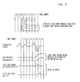
- An example of a printing defect causing an error in both the correlation circuitry and in the peak in error circuitry is shown in Fig. 2.
- the character "6" shown at the top of the figure has a left hand border which comprises an embossed edge shown by the heavy line instead of the normal trailing edge indicated by the dotted vertical line.
- the character signal waveform resulting from the scanning of the character, as shown, provides an output as indicated in the topmost waveform shown in Fig. 2.
- the dotted waveform shown in zone 6 represents the normal waveform which would be seen if the character were properly formed, while the solid line shows the distorted portion of the waveform extending into zone 7 resulting from the heavy embossed edge.
- the next two waveforms show the integrator signals for zones 6 and 7 and the resulting time zone correlation results in a conflict between the character "6" which is the correct character shown and a symbol "SS3" which is caused by the malformed portion of character 6.
- a test for a signal existing between time zone 6 and time zone 7 provides a peak in error signal at the boundary between lines 6 and 7 and also provides a peak in error signal in time zone 7 which should not exist.
- the adaptive timing system corrects the timing boundary according to the information relating to peaks and wave amplitudes found in the previous two peaks. If a peak is detected late within the fixed time boundaries and the previous peak does not signify that the system is dealing with a narrow line, the following boundary is displaced in time. The time displacement is determined by absolute location of the previous peak and is controlled to make the peak appear as if located in the center of the time zone. Following boundaries are not affected unless the associated signal is also distorted. Additional information is used in the beginning third of the character to determine if correction is needed. This circuit, known as the inhibit delay trigger, looks for particular peak sequences such as the character described as "SS3".
- this character does not need displaced boundaries to separate it from the other 13 characters in the usual font to be recognized.
- This system according to the present invention is also capable of correcting a peak of the curve just after the fixed time boundary by resetting the associated integrator.
- This circuit is known as the force integrator TZX extension.
- Fig. 3 of the drawings shows a single gap magnetic ink character recognition system similar to that shown in Fig. 1, but including the adaptive timing circuits which comprise the present invention.
- This showing is in a broad schematic form and is used to illustrate the manner in which the adaptive timing circuits are included in the recognition circuit of the type already known in the art.
- the adaptive timing circuits 39 are essentially introduced between the timing control oscillator 13 and the remainder of the recognition system.
- the control line to the integrator resets, 17 as well the lines 31 and 33 to the peak signal and time zone detectors now emanate from the adaptive timing circuits 39 rather than from the timing control 13.
- the adaptive timing control utilizes a full wave rectified signal plus peak levels Supplied from the detector circuits 29 and utilizes an input in the timing circuits 39.
- the output of peak detector 11 is supplied to the timing circuits 39 via the timing control oscillator 13 as in the arrangement shown in Fig. 1.
- Figs. 4A, 4B, 4C and 4D are diagrammatic views of waveforms encountered at various points in the system, illustrating the manner in which the adaptive timing circuits operate.
- Fig. 4A shows a character "6" in which the shaded area shows an embossed portion which represents defective printing and which in the usual instance would cause a mistaken reading by prior known systems.
- Fig. 4B shows a waveform of the inducedMICR signal resulting from scanning an idealized character 6, illustrating the relationships of the various portions of the scan signal with the basic time zones designated O through 8 as manifest from the drawing.
- Fig. 4C shows the time zones as adjusted by the adaptive timing system, with the delayed peaks shown in their re-_ lationship to the time zones 1 and 6.
- Fig. 4D shows the relationship between the induced MICR signals resulting from scanning a defective character 6 such as shown in Fig. 4A, and the relationship of that waveform to the various signals developed in the system utilizing the adaptive timing arrangement. Note that the two negative going peaks in time zones 1 and 7 are displaced from their normal position.
- the waveform designated as Control 1, reference character .41 is a square wave having equal on and off times and extending over the duration of the basic time zone, such as, for example, the time zone TZ1.
- the waveform for the basic sample time zones and the sample time zone signals 45 when the adaptive timing system is provided It will be noted that a delay.time is added to the off time of the first cycle, as designated in the drawing by the legend "sample TZ delay.”
- the next pair of waveforms are the signals described as sample between TZ, and comprised of waveforms 47 and 49. Again, it will be noted that the sample between time zone signal is altered by the amount of the delay designated by the legend BTZ Delay and shown in the drawing.
- the next pair of waveforms are the resetting signals for zone 2, designated by reference characters 51 and 53 in which the reset signal is delayed by an amount indicated by the legend INTG TZ Delay as shown in the drawing.
- the next pair of signals are the reset integrator signals for zone 7, designated by reference characters 55 and 57.
- an output pulse 59 is provided on the waveform 57, and is designated as Force INTG TZX Extension.
- the waveforms 61 and 63 show the signals generated by the integrator for time zone 7 without and with the adaptive timing system respectively. It can be seen that the integrated curve 63 is reset by the additional pulse 59 and the waveform 57.
- Fig. 5 is a more detailed schematic block diagram of the-adaptive timing circuits shown generally by the block 39 of Fig. 3.
- the input signals are mainly supplied from the system clock or oscillator 13 of Fig. 3, and to simplify the drawing, the source of each signal is indicated on the drawing as conventional manually operated switches, rather than the logical circuits which would be actually employed. Suffice it to say that when the switches shown are closed the signals indicated by the accompanying legend are supplied as inputs to the circuit elements shown in the drawings.
- the amplified analog signals are full-wave rectified and supplied to the peak detection and discriminator circuit 69, and are supplied as one input to an AND circuit 71.
- a Second input to this AND circuit is a peak level signal controlled by switch 73, and a third input is supplied via a switch 75, and comprises the timing signals for the 8 time zones, designated by the legend TZ timing.
- the output of the circuit 71 constitutes the set input for a delay trigger 77. This trigger sets the delay timing into operation. This trigger is reset by terminating conditions which result in a reset signal being supplied from an OR circuit 79.
- the first criteria for resetting the trigger 77 is detection of a narrow line in the character.
- Switches 81 and 83 control the positive and negative level inputs to a narrow line detector 85', which is also rendered effective by an "on" output from trigger 77, on line 103.
- the output of detector 85 on line 86 comprises one input to OR circuit 79.
- a second resetting circuit is provided by the inhibit delay trigger output on a line 87.
- Inputs to trigger 89 are governed by switches 91, 93 and 95, governing the supply of signals "peak level”, “Intg TZ", and “TZ Timing” respectively.
- the remaining reset signal to trigger 77 is supplied by the delay time-out element 97.
- This element which may comprise, for example, an appropriate counter or cascaded single-shot multivibrator provides a plurality of timed output pulses at intervals determined by signals from the base oscillator, governed by switch 101.
- the delay time-out cycle is initiated by a signal on the output line 103 of trigger 77 and the final time-out signal on line 105 is supplied to OR circuit 79, to thereby reset trigger 77.
- the Force Integrator TZX Extension Circuit 106 combines off signals from the delay trigger 77, on line 107 and the inhibit delay trigger 89, on line 109. Also supplied to this circuit, via switches 111, 113 and 115 are the signals peak level, INTG TZ signals and TZ timing signals, as shown.
- the delay trigger latch is set to drive the delay time-out counter at the speed of the base oscillator frequency rate.
- This delay time-out counter determines the amount of time delay on the between TZ sampling pulses, on the sample TZ sampling pulses, as well as on the extension of the Intg Zne X reset.
- the delays will be terminated as soon as the delay time-out expires or when a "narrow line condition" is detected and the induced MICR signal swings across the reference level.
- the "Force Intg TZx Extension" circuit looks for a very strong negative peak, which is within the first division of the six segments of the TZX+1, together with the previous information that also indicates it is a possible delayed peak. This forces a TZx+1 integrator reset pulse at the third divison of of the six segments of TZx+1 to remove the energy which has already been accumulated from integrator TZx+1. It is essentially the same as extending TZx boundary 1/2 time zone further for the peak of that character to the integrating and correlating networks.
- An example of how the "Force Intg TZx Extension" circuit works on a distorted signal of character six is shown in Fig. 4 by generating an extra reset pulse for Intg Zne 7 to remove the incorrect energy away from Intg 7.
- the "inhibit delay trigger" circuit is designed to differentiate the narrow line SS3 character from the reset. It is looking for certain conditions between the TZ2 and TZ3 boundary. When the conditions are met, the adaptive timing logic will be disabled.
Landscapes
- Engineering & Computer Science (AREA)
- Computer Vision & Pattern Recognition (AREA)
- Physics & Mathematics (AREA)
- General Physics & Mathematics (AREA)
- Multimedia (AREA)
- Theoretical Computer Science (AREA)
- Character Discrimination (AREA)
- Character Input (AREA)
Applications Claiming Priority (2)
| Application Number | Priority Date | Filing Date | Title |
|---|---|---|---|
| US163672 | 1980-06-27 | ||
| US06/163,672 US4356472A (en) | 1980-06-27 | 1980-06-27 | Character recognition system |
Publications (3)
| Publication Number | Publication Date |
|---|---|
| EP0042944A2 true EP0042944A2 (fr) | 1982-01-06 |
| EP0042944A3 EP0042944A3 (en) | 1982-09-29 |
| EP0042944B1 EP0042944B1 (fr) | 1985-10-30 |
Family
ID=22591072
Family Applications (1)
| Application Number | Title | Priority Date | Filing Date |
|---|---|---|---|
| EP81103612A Expired EP0042944B1 (fr) | 1980-06-27 | 1981-05-12 | Système de reconnaissance de caractères |
Country Status (5)
| Country | Link |
|---|---|
| US (1) | US4356472A (fr) |
| EP (1) | EP0042944B1 (fr) |
| JP (1) | JPS6034158B2 (fr) |
| CA (1) | CA1162309A (fr) |
| DE (1) | DE3172748D1 (fr) |
Cited By (3)
| Publication number | Priority date | Publication date | Assignee | Title |
|---|---|---|---|---|
| WO1989012283A1 (fr) * | 1988-06-06 | 1989-12-14 | Ncr Corporation | Appareil de lecture de caracteres magnetiques |
| WO1991006922A1 (fr) * | 1989-10-24 | 1991-05-16 | Unisys Corporation | Appareil de reconnaissance de caracteres |
| US8636214B2 (en) | 2011-10-25 | 2014-01-28 | International Business Machines Corporation | Recognition of encoded information on documents |
Families Citing this family (19)
| Publication number | Priority date | Publication date | Assignee | Title |
|---|---|---|---|---|
| WO1986004208A1 (fr) * | 1984-12-28 | 1986-07-17 | Micro Engineering Co., Ltd. | Procede d'empilage de cartes de circuits imprimes |
| US4797938A (en) * | 1985-10-15 | 1989-01-10 | International Business Machines Corporation | Method of identifying magnetic ink (MICR) characters |
| US5054092A (en) * | 1988-03-31 | 1991-10-01 | Checkmate Electronics, Inc. | Hand-operated low cost magnetic character recognition system |
| US4913182A (en) * | 1989-03-24 | 1990-04-03 | Sloan Valve Company | Plumbing fixture check stop |
| US5201010A (en) * | 1989-05-01 | 1993-04-06 | Credit Verification Corporation | Method and system for building a database and performing marketing based upon prior shopping history |
| US5644723A (en) * | 1989-05-01 | 1997-07-01 | Credit Verification Corporation | Method and system for selective incentive point-of-sale marketing in response to customer shopping histories |
| US5687322A (en) | 1989-05-01 | 1997-11-11 | Credit Verification Corporation | Method and system for selective incentive point-of-sale marketing in response to customer shopping histories |
| US8700458B2 (en) | 1989-05-01 | 2014-04-15 | Catalina Marketing Corporation | System, method, and database for processing transactions |
| US5305196A (en) | 1989-05-01 | 1994-04-19 | Credit Verification Corporation | Check transaction processing, database building and marketing method and system utilizing automatic check reading |
| US5237620A (en) * | 1989-05-01 | 1993-08-17 | Credit Verification Corporation | Check reader method and system for reading check MICR code |
| US5621812A (en) * | 1989-05-01 | 1997-04-15 | Credit Verification Corporation | Method and system for building a database for use with selective incentive marketing in response to customer shopping histories |
| US5026974A (en) * | 1989-12-27 | 1991-06-25 | Ncr Corporation | Method for recognizing the leading edge of a character in E13B font |
| US5134663A (en) * | 1991-04-19 | 1992-07-28 | Unisys Corporation | Center line magnetic ink character recognition system |
| US6292786B1 (en) | 1992-05-19 | 2001-09-18 | Incentech, Inc. | Method and system for generating incentives based on substantially real-time product purchase information |
| US6609104B1 (en) | 1999-05-26 | 2003-08-19 | Incentech, Inc. | Method and system for accumulating marginal discounts and applying an associated incentive |
| US6993498B1 (en) | 1999-07-15 | 2006-01-31 | Midnight Blue Remote Access, Llc | Point-of-sale server and method |
| US6956962B1 (en) * | 2002-05-07 | 2005-10-18 | Unisys Corporation | System and method of signal processing for use in reading data |
| US7796798B2 (en) * | 2006-05-17 | 2010-09-14 | International Business Machines Corporation | Frequency domain based MICR reader |
| US8023718B1 (en) * | 2007-01-16 | 2011-09-20 | Burroughs Payment Systems, Inc. | Method and system for linking front and rear images in a document reader/imager |
Citations (6)
| Publication number | Priority date | Publication date | Assignee | Title |
|---|---|---|---|---|
| DE1147791B (de) * | 1960-06-23 | 1963-04-25 | Gen Electric | Einrichtung zum Erkennen von Wellenzuegen bei automatischen Lesegeraeten |
| US3629829A (en) * | 1969-09-09 | 1971-12-21 | Ibm | Character recognition circuitry |
| DE1549766B2 (de) * | 1966-05-27 | 1972-09-28 | International Business Machines Corp., Armonk, N.Y. (V.StA.) | Zeichenerkennungsgeraet |
| DE2728594A1 (de) * | 1976-06-25 | 1978-01-05 | Recognition Equipment Inc | Magnetischer leser fuer strichkodierte zeichen |
| US4148010A (en) * | 1977-10-31 | 1979-04-03 | Ncr Canada Ltd. - Ncr Canada Ltee | Magnetic ink character reader system |
| DE2847302A1 (de) * | 1977-10-31 | 1979-05-03 | Ncr Canada | Zeichenerkennungsvorrichtung |
Family Cites Families (4)
| Publication number | Priority date | Publication date | Assignee | Title |
|---|---|---|---|---|
| US3535682A (en) * | 1965-12-10 | 1970-10-20 | Lundy Electronics & Syst Inc | Waveform recognition system |
| US3987411A (en) * | 1975-08-11 | 1976-10-19 | Burroughs Corporation | Character recognition system employing extraneous and required peak detection with variable threshold controlled timing |
| US4143355A (en) * | 1977-08-29 | 1979-03-06 | Signature Guardian Systems, Inc. | Character recognition system |
| US4277776A (en) * | 1979-10-01 | 1981-07-07 | Ncr Canada Ltd - Ncr Canada Ltee | Magnetic ink character recognition apparatus |
-
1980
- 1980-06-27 US US06/163,672 patent/US4356472A/en not_active Expired - Lifetime
-
1981
- 1981-04-20 JP JP56058704A patent/JPS6034158B2/ja not_active Expired
- 1981-05-06 CA CA000376943A patent/CA1162309A/fr not_active Expired
- 1981-05-12 DE DE8181103612T patent/DE3172748D1/de not_active Expired
- 1981-05-12 EP EP81103612A patent/EP0042944B1/fr not_active Expired
Patent Citations (6)
| Publication number | Priority date | Publication date | Assignee | Title |
|---|---|---|---|---|
| DE1147791B (de) * | 1960-06-23 | 1963-04-25 | Gen Electric | Einrichtung zum Erkennen von Wellenzuegen bei automatischen Lesegeraeten |
| DE1549766B2 (de) * | 1966-05-27 | 1972-09-28 | International Business Machines Corp., Armonk, N.Y. (V.StA.) | Zeichenerkennungsgeraet |
| US3629829A (en) * | 1969-09-09 | 1971-12-21 | Ibm | Character recognition circuitry |
| DE2728594A1 (de) * | 1976-06-25 | 1978-01-05 | Recognition Equipment Inc | Magnetischer leser fuer strichkodierte zeichen |
| US4148010A (en) * | 1977-10-31 | 1979-04-03 | Ncr Canada Ltd. - Ncr Canada Ltee | Magnetic ink character reader system |
| DE2847302A1 (de) * | 1977-10-31 | 1979-05-03 | Ncr Canada | Zeichenerkennungsvorrichtung |
Cited By (3)
| Publication number | Priority date | Publication date | Assignee | Title |
|---|---|---|---|---|
| WO1989012283A1 (fr) * | 1988-06-06 | 1989-12-14 | Ncr Corporation | Appareil de lecture de caracteres magnetiques |
| WO1991006922A1 (fr) * | 1989-10-24 | 1991-05-16 | Unisys Corporation | Appareil de reconnaissance de caracteres |
| US8636214B2 (en) | 2011-10-25 | 2014-01-28 | International Business Machines Corporation | Recognition of encoded information on documents |
Also Published As
| Publication number | Publication date |
|---|---|
| JPS5714975A (en) | 1982-01-26 |
| US4356472A (en) | 1982-10-26 |
| DE3172748D1 (en) | 1985-12-05 |
| CA1162309A (fr) | 1984-02-14 |
| EP0042944B1 (fr) | 1985-10-30 |
| EP0042944A3 (en) | 1982-09-29 |
| JPS6034158B2 (ja) | 1985-08-07 |
Similar Documents
| Publication | Publication Date | Title |
|---|---|---|
| US4356472A (en) | Character recognition system | |
| US4053737A (en) | Magnetic reader for bar encoded characters | |
| US4148010A (en) | Magnetic ink character reader system | |
| US3089123A (en) | Character recognition quantizing apparatus | |
| US4143355A (en) | Character recognition system | |
| EP0027547B1 (fr) | Appareil de détection de signaux de données | |
| US3932840A (en) | Error detection and sequence maintaining system for bar-code readers | |
| US5396370A (en) | Process for evaluating binary data of a magnetic storage card | |
| JPH05500721A (ja) | 調整可能なしきい値を有する磁気コード読取装置 | |
| US3938089A (en) | Double read system for character recognition systems | |
| US4218612A (en) | Magnetic signal detector | |
| US3638238A (en) | Magnetic ink symbol recognition system with waveshapes representing direct magnetic flux | |
| US3879707A (en) | Character recognition system for bar coded characters | |
| US3571793A (en) | Character recognition systems | |
| WO1989012868A1 (fr) | Methode et appareil pour lire des caracteres | |
| US5153788A (en) | Method of recording and detecting servo information for positioning magnetic head | |
| EP0729148A2 (fr) | Méthode et appareil pour la qualification des impulsions de données dans un signal de suite de données, reproduit par un transducteur magnétique | |
| US3212058A (en) | Null dependent symbol recognition | |
| US4578720A (en) | Self-clocking code demodulator with error detecting capability | |
| EP0451252B1 (fr) | Appareil de reconnaissance de caracteres par detection de rapports | |
| EP0344301B1 (fr) | Procede et appareil pour lire des caracteres | |
| US5257319A (en) | Character recognition apparatus | |
| JPS6232546B2 (fr) | ||
| JP3209315B2 (ja) | 磁気データリーダ装置 | |
| US4813059A (en) | Readback recovery of run length limited codes |
Legal Events
| Date | Code | Title | Description |
|---|---|---|---|
| PUAI | Public reference made under article 153(3) epc to a published international application that has entered the european phase |
Free format text: ORIGINAL CODE: 0009012 |
|
| 17P | Request for examination filed |
Effective date: 19811027 |
|
| AK | Designated contracting states |
Designated state(s): DE FR GB IT |
|
| PUAL | Search report despatched |
Free format text: ORIGINAL CODE: 0009013 |
|
| AK | Designated contracting states |
Designated state(s): DE FR GB IT |
|
| GRAA | (expected) grant |
Free format text: ORIGINAL CODE: 0009210 |
|
| AK | Designated contracting states |
Designated state(s): DE FR GB IT |
|
| REF | Corresponds to: |
Ref document number: 3172748 Country of ref document: DE Date of ref document: 19851205 |
|
| ITF | It: translation for a ep patent filed | ||
| ET | Fr: translation filed | ||
| PLBE | No opposition filed within time limit |
Free format text: ORIGINAL CODE: 0009261 |
|
| STAA | Information on the status of an ep patent application or granted ep patent |
Free format text: STATUS: NO OPPOSITION FILED WITHIN TIME LIMIT |
|
| 26N | No opposition filed | ||
| PGFP | Annual fee paid to national office [announced via postgrant information from national office to epo] |
Ref country code: GB Payment date: 19910419 Year of fee payment: 11 |
|
| PGFP | Annual fee paid to national office [announced via postgrant information from national office to epo] |
Ref country code: FR Payment date: 19910430 Year of fee payment: 11 |
|
| PGFP | Annual fee paid to national office [announced via postgrant information from national office to epo] |
Ref country code: DE Payment date: 19910525 Year of fee payment: 11 |
|
| ITTA | It: last paid annual fee | ||
| PG25 | Lapsed in a contracting state [announced via postgrant information from national office to epo] |
Ref country code: GB Effective date: 19920512 |
|
| GBPC | Gb: european patent ceased through non-payment of renewal fee |
Effective date: 19920512 |
|
| PG25 | Lapsed in a contracting state [announced via postgrant information from national office to epo] |
Ref country code: FR Effective date: 19930129 |
|
| PG25 | Lapsed in a contracting state [announced via postgrant information from national office to epo] |
Ref country code: DE Effective date: 19930202 |
|
| REG | Reference to a national code |
Ref country code: FR Ref legal event code: ST |