EP0042757B1 - Mécanismes de loquets - Google Patents
Mécanismes de loquets Download PDFInfo
- Publication number
- EP0042757B1 EP0042757B1 EP81302812A EP81302812A EP0042757B1 EP 0042757 B1 EP0042757 B1 EP 0042757B1 EP 81302812 A EP81302812 A EP 81302812A EP 81302812 A EP81302812 A EP 81302812A EP 0042757 B1 EP0042757 B1 EP 0042757B1
- Authority
- EP
- European Patent Office
- Prior art keywords
- bolt
- plate
- latch mechanism
- mechanism according
- deadlatch
- Prior art date
- Legal status (The legal status is an assumption and is not a legal conclusion. Google has not performed a legal analysis and makes no representation as to the accuracy of the status listed.)
- Expired
Links
Images


Classifications
-
- E—FIXED CONSTRUCTIONS
- E05—LOCKS; KEYS; WINDOW OR DOOR FITTINGS; SAFES
- E05B—LOCKS; ACCESSORIES THEREFOR; HANDCUFFS
- E05B55/00—Locks in which a sliding latch is used also as a locking bolt
Definitions
- This invention is concerned with latch mechanisms such as those which are used on doors.
- the invention is distinguished from the device disclosed in the above mentioned United States Patent in that the operating handle is slidably movable with respect to the casing so as to act on a bolt plate carrying the bolt, and wherein the drive member and the operating handle engage independently with the bolt plate for operation of the bolt.
- the handle is linked with the bolt plate through a handle plate which defines a slot receiving the rotatable drive shaft which is formed, in the region of the slot, with a groove cut in the side of the drive shaft, or a projection from the side of the drive shaft, the slot providing a track extending in the direction of movement of the plate and notches extending generally at right angles to the track such that, when the drive shaft is in one attitude the track may slide thereabout, the drive shaft being rotatable from that attitude to locate within one of the notches to prevent sliding of the handle plate.
- a further preferred embodiment of the invention incorporates a deadlatch which can slide between an extended position wherein it projects through the one end of the casing and a retracted position wherein it is at least partially withdrawn into the casing, the deadlatch being carried by a deadlatch plate which forms part of a deadlatch mechanism also incorporating a bolt securing member which is held by the deadlatch plate out of contact with the bolt plate when the deadlatch is in the extended position but which is driven into locking engagement with a part of the bolt plate so as to prevent movement of the bolt to the retracted position when the bolt is extended and the deadlatch is in the retracted position, the drive member being operable to disengage a part of the bolt securing member from the notch in the bolt plate.
- a latch hold mechanism incorporated in a plate which causes movement of the bolt between its two positions defined by a slot in the plate, the edge of which slot may be engaged by a notch at the end of a hold member, the hold member being biased to raise the notched end thereof free of the slot in the plate when the edge of the slot in the plate is disengaged from the notch, the hold member also incorporating an actuating portion which can be pressed against the bias to allow the notch to engage with the edge of the slot in the plate.
- the hold member is biased by integral spring-like arms thereof acting on part of the casing, and the actuating portion is a button extending through the casing.
- Retaining means may be included for preventing the hold member from being removed from the casing.
- This retaining means can comprise projecting resilient flaps on part of the hold member sliding within a sleeve of the casing, the sleeve carrying flanges against which the flaps will abut when the hold member is disengaged and biased away from the plate.
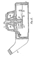
- the latch mechanism illustrated in Figures 1 and 2 comprises a body 1 which houses parts for operating a bolt 2 which will be received within an opening 3 in a staple 4 which will be attached to a door frame.
- the mechanism within the body 1 also operates a deadlatch nose 5.
- the bolt 2 may be withdrawn by pulling a handle 6 in a sliding motion in the direction away from the staple 4.
- the handle 6 may be held in the open condition (fully retracted) by pressing a hold button 7, the operation of which will be described later.
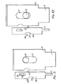
- the lock moulding 13 has a slot 25 formed therein leaving a semi-circular portion 26 which can be moved into or out of one of a pair of notches 27, 28 in the hold plate 23.
- the stepped plate 22 carrying the hold plate 23 can slide freely backwards and forwards about the portion 26 of the lock moulding 13.
- the lock moulding 13 can be rotated through 90° into the condition illustrated in Figure 7 so as to locate in a notch 27 in the hold plate 23 whereby the stepped plate 22 is locked against sliding movement.
- the handle 6 may be held in the retracted position temporarily by means of the hold button 7.
- the hold button 7 comprises a moulded body of a resilient plastics material formed at its lower end with a notch 32.
- this notch 32 can locate about a reduced portion 33 of the stepped plate 22 as the tip 34 of the hold button 7 passes into an opening 35 due to pressure applied to the face of the button 7.
- the moulded hold button body incorporates a pair of resilient arms 36 which react against a part of the moulded portion 11 of the body 1 and thus bias the hold button 7 outwardly of the portion 11.
Landscapes
- Lock And Its Accessories (AREA)
- Ignition Installations For Internal Combustion Engines (AREA)
- Vehicle Body Suspensions (AREA)
- Medicines Containing Antibodies Or Antigens For Use As Internal Diagnostic Agents (AREA)
- Axle Suspensions And Sidecars For Cycles (AREA)
Claims (21)
Priority Applications (1)
| Application Number | Priority Date | Filing Date | Title |
|---|---|---|---|
| AT81302812T ATE12132T1 (de) | 1980-06-24 | 1981-06-23 | Fallenmechanismen. |
Applications Claiming Priority (2)
| Application Number | Priority Date | Filing Date | Title |
|---|---|---|---|
| GB8020677A GB2080382A (en) | 1980-06-24 | 1980-06-24 | Improvements relating to latch mechanisms |
| GB8020677 | 1980-06-24 |
Publications (2)
| Publication Number | Publication Date |
|---|---|
| EP0042757A1 EP0042757A1 (fr) | 1981-12-30 |
| EP0042757B1 true EP0042757B1 (fr) | 1985-03-13 |
Family
ID=10514285
Family Applications (1)
| Application Number | Title | Priority Date | Filing Date |
|---|---|---|---|
| EP81302812A Expired EP0042757B1 (fr) | 1980-06-24 | 1981-06-23 | Mécanismes de loquets |
Country Status (4)
| Country | Link |
|---|---|
| EP (1) | EP0042757B1 (fr) |
| AT (1) | ATE12132T1 (fr) |
| DE (1) | DE3169242D1 (fr) |
| GB (1) | GB2080382A (fr) |
Families Citing this family (1)
| Publication number | Priority date | Publication date | Assignee | Title |
|---|---|---|---|---|
| ES2137792B1 (es) * | 1995-07-31 | 2000-05-16 | Talleres Escoriaza Sa | Cerradura perfeccionada. |
Family Cites Families (2)
| Publication number | Priority date | Publication date | Assignee | Title |
|---|---|---|---|---|
| US1513904A (en) * | 1922-10-07 | 1924-11-04 | Elert A Hill | Lock mechanism |
| US3765710A (en) * | 1971-05-10 | 1973-10-16 | Keystone Consolidated Ind Inc | Dual action night latch and lock |
-
1980
- 1980-06-24 GB GB8020677A patent/GB2080382A/en not_active Withdrawn
-
1981
- 1981-06-23 DE DE8181302812T patent/DE3169242D1/de not_active Expired
- 1981-06-23 AT AT81302812T patent/ATE12132T1/de not_active IP Right Cessation
- 1981-06-23 EP EP81302812A patent/EP0042757B1/fr not_active Expired
Also Published As
| Publication number | Publication date |
|---|---|
| DE3169242D1 (en) | 1985-04-18 |
| ATE12132T1 (de) | 1985-03-15 |
| GB2080382A (en) | 1982-02-03 |
| EP0042757A1 (fr) | 1981-12-30 |
Similar Documents
| Publication | Publication Date | Title |
|---|---|---|
| US5116261A (en) | Auxiliary computer panel to cover a disk drive access side of a computer casing | |
| KR890003023B1 (ko) | 도어정 조립체 | |
| US6848728B2 (en) | Window fastener | |
| JP2533004B2 (ja) | トランク扉等の電動式ロック装置 | |
| JPH07166750A (ja) | 車両用扉のロック装置 | |
| JPH0662150U (ja) | 引出し回転型扉用ロックハンドル装置 | |
| US5984384A (en) | Vehicle door latch device with self-cancelling mechanism | |
| KR930016631A (ko) | 좌향 당김문 및 우향 당김문 겸용 도어로크 핸들장치 | |
| US5056835A (en) | Latching mechanism for a closure with a disconnectable handle and a sliding catch | |
| EP0141020B1 (fr) | Equipement de manipulation pour portes | |
| EP1485557B1 (fr) | Dispositif de serrure avec verrou a poucier | |
| EP0042757B1 (fr) | Mécanismes de loquets | |
| JPH08135279A (ja) | 左右兼用型扉用ロックハンドル装置 | |
| KR100638246B1 (ko) | 도어의 잠금장치 | |
| EP1179108B1 (fr) | Verrou | |
| US4121864A (en) | Latch assembly | |
| US4995653A (en) | Door lock apparatus | |
| US4858969A (en) | Door latch assembly | |
| US4147045A (en) | Combination lock with scrambler | |
| JPH11141207A (ja) | ラッチ錠 | |
| JP3844812B2 (ja) | 電気錠装置 | |
| US4784416A (en) | Door latch | |
| GB2297799A (en) | Handle assembly | |
| JPH0344936Y2 (fr) | ||
| JPH0635090Y2 (ja) | 車両用ドアロック機構の施錠解錠装置 |
Legal Events
| Date | Code | Title | Description |
|---|---|---|---|
| PUAI | Public reference made under article 153(3) epc to a published international application that has entered the european phase |
Free format text: ORIGINAL CODE: 0009012 |
|
| AK | Designated contracting states |
Designated state(s): AT BE CH DE FR GB IT LU NL SE |
|
| 17P | Request for examination filed |
Effective date: 19820623 |
|
| GRAA | (expected) grant |
Free format text: ORIGINAL CODE: 0009210 |
|
| AK | Designated contracting states |
Designated state(s): AT BE CH DE FR GB IT LI LU NL SE |
|
| PG25 | Lapsed in a contracting state [announced via postgrant information from national office to epo] |
Ref country code: SE Effective date: 19850313 Ref country code: NL Effective date: 19850313 Ref country code: LI Effective date: 19850313 Ref country code: IT Free format text: LAPSE BECAUSE OF FAILURE TO SUBMIT A TRANSLATION OF THE DESCRIPTION OR TO PAY THE FEE WITHIN THE PRESCRIBED TIME-LIMIT;WARNING: LAPSES OF ITALIAN PATENTS WITH EFFECTIVE DATE BEFORE 2007 MAY HAVE OCCURRED AT ANY TIME BEFORE 2007. THE CORRECT EFFECTIVE DATE MAY BE DIFFERENT FROM THE ONE RECORDED. Effective date: 19850313 Ref country code: FR Free format text: THE PATENT HAS BEEN ANNULLED BY A DECISION OF A NATIONAL AUTHORITY Effective date: 19850313 Ref country code: CH Effective date: 19850313 Ref country code: BE Effective date: 19850313 Ref country code: AT Effective date: 19850313 |
|
| REF | Corresponds to: |
Ref document number: 12132 Country of ref document: AT Date of ref document: 19850315 Kind code of ref document: T |
|
| REF | Corresponds to: |
Ref document number: 3169242 Country of ref document: DE Date of ref document: 19850418 |
|
| REG | Reference to a national code |
Ref country code: CH Ref legal event code: PL |
|
| PG25 | Lapsed in a contracting state [announced via postgrant information from national office to epo] |
Ref country code: LU Free format text: LAPSE BECAUSE OF NON-PAYMENT OF DUE FEES Effective date: 19850630 |
|
| NLV1 | Nl: lapsed or annulled due to failure to fulfill the requirements of art. 29p and 29m of the patents act | ||
| EN | Fr: translation not filed | ||
| PLBE | No opposition filed within time limit |
Free format text: ORIGINAL CODE: 0009261 |
|
| STAA | Information on the status of an ep patent application or granted ep patent |
Free format text: STATUS: NO OPPOSITION FILED WITHIN TIME LIMIT |
|
| PG25 | Lapsed in a contracting state [announced via postgrant information from national office to epo] |
Ref country code: DE Effective date: 19860301 |
|
| 26N | No opposition filed | ||
| PGFP | Annual fee paid to national office [announced via postgrant information from national office to epo] |
Ref country code: GB Payment date: 19900620 Year of fee payment: 10 |
|
| PG25 | Lapsed in a contracting state [announced via postgrant information from national office to epo] |
Ref country code: GB Effective date: 19910623 |
|
| GBPC | Gb: european patent ceased through non-payment of renewal fee |