EP0042609A1 - Process for lowering the electrodes of an electric arc furnace - Google Patents
Process for lowering the electrodes of an electric arc furnace Download PDFInfo
- Publication number
- EP0042609A1 EP0042609A1 EP81104756A EP81104756A EP0042609A1 EP 0042609 A1 EP0042609 A1 EP 0042609A1 EP 81104756 A EP81104756 A EP 81104756A EP 81104756 A EP81104756 A EP 81104756A EP 0042609 A1 EP0042609 A1 EP 0042609A1
- Authority
- EP
- European Patent Office
- Prior art keywords
- electrodes
- electrode
- furnace
- support plates
- clamps
- Prior art date
- Legal status (The legal status is an assumption and is not a legal conclusion. Google has not performed a legal analysis and makes no representation as to the accuracy of the status listed.)
- Granted
Links
Images


Classifications
-
- F—MECHANICAL ENGINEERING; LIGHTING; HEATING; WEAPONS; BLASTING
- F27—FURNACES; KILNS; OVENS; RETORTS
- F27B—FURNACES, KILNS, OVENS, OR RETORTS IN GENERAL; OPEN SINTERING OR LIKE APPARATUS
- F27B3/00—Hearth-type furnaces, e.g. of reverberatory type; Tank furnaces
- F27B3/08—Hearth-type furnaces, e.g. of reverberatory type; Tank furnaces heated electrically, with or without any other source of heat
- F27B3/085—Arc furnaces
-
- F—MECHANICAL ENGINEERING; LIGHTING; HEATING; WEAPONS; BLASTING
- F27—FURNACES; KILNS; OVENS; RETORTS
- F27D—DETAILS OR ACCESSORIES OF FURNACES, KILNS, OVENS, OR RETORTS, IN SO FAR AS THEY ARE OF KINDS OCCURRING IN MORE THAN ONE KIND OF FURNACE
- F27D11/00—Arrangement of elements for electric heating in or on furnaces
- F27D11/08—Heating by electric discharge, e.g. arc discharge
- F27D11/10—Disposition of electrodes
-
- H—ELECTRICITY
- H05—ELECTRIC TECHNIQUES NOT OTHERWISE PROVIDED FOR
- H05B—ELECTRIC HEATING; ELECTRIC LIGHT SOURCES NOT OTHERWISE PROVIDED FOR; CIRCUIT ARRANGEMENTS FOR ELECTRIC LIGHT SOURCES, IN GENERAL
- H05B7/00—Heating by electric discharge
- H05B7/02—Details
- H05B7/10—Mountings, supports, terminals or arrangements for feeding or guiding electrodes
Definitions
- the invention relates to a method for releasing the electrodes of an electric arc furnace releasably clipped by vertically displaceable electrode arms.
- the electrodes of an electric arc furnace are subject to erosion, with the result that the length of the electrodes decreases continuously in the course of a melt. It is therefore necessary after exhaustion of the adjustment stroke, which can be regulated as a function of the burn-up speed, of the electrode arms releasably gripping the electrodes, lifting the clasping, then releasing the electrodes relative to the electrode arms and then re-tightening the electrode arms on the electrodes in order to continue to regulate the tracking Ensure electrodes during the subsequent melting process.
- the electrodes can be released in a known manner, for example before the first basket filled with scrap is charged.
- the electrode arms are first moved to the lowest position with the furnace lid remaining restricted above the furnace vessel. Then a crane picks up the electrode carrying nipple, so that the clasping of this electrode can be released.
- the electrode is then lowered by the crane by a predetermined amount, which restores the correct removal of the electrode tip from the bottom of the furnace vessel.
- the electrode arm in question can then be clamped to the electrode again.
- the crane can now be used to release the other electrodes.
- the advantage of this method is that the electrodes can be released exactly.
- the high is a disadvantage Loss of time because the furnace vessel is not accessible while the electrodes are releasing and therefore charging is not possible.
- the electrodes In practice, in order to reduce the loss of time when the electrodes are released, the electrodes have been released using a crane as soon as the electrodes have worked their way through the scrap and the electrode arms have reached the lowest position. This method is used in particular where only a single crane is available for an electric arc furnace.
- the clasping of the electrode is released and the electrode arm is then moved upwards by an amount which must necessarily be estimated by the melter. Once the height determined by the melter has been reached, the electrode arm is clamped to the electrode again and the other electrodes are then released.
- a major disadvantage of this method is that it is only a matter of the ability of the melter to estimate how exactly the relaxation of each individual electrode is carried out and its height is brought into line with the height of the other electrodes.
- the arc between the electrode tip and the material to be melted will lead to an unstable arc, which inevitably increases the melting time and increases the energy consumption.
- the stove lining can be easily damaged if an electrode has been worn too much.
- the electrodes were decayed when the first scrap basket had been charged and the arc was present at all electrodes.
- the arc furnace is then switched off and the electrodes are loosened together or in succession.
- the electrodes slide or fall down until the electrode tips hit the scrap.
- the electrode arms are then raised by an amount which in turn can only be estimated by the smelter for each electrode.
- the electrode arms are clamped back to the electrodes and the arc furnace is switched on.
- the easing of the electrodes with the support of the scrap is associated with the least loss of production time, but has the disadvantage of a very imprecise adjustment of the electrodes to the melt.
- the electrodes can be damaged relatively quickly if the electrode tips hit oblique, sharp-edged shot parts.
- the invention is therefore based on the object of providing a method for releasing the electrodes of an electric arc furnace, by means of which an exact release of the electrodes is ensured without loss of production time while avoiding the risk of electrode damage.
- the essence of the inventive concept is the possibility of having work processes run in parallel, which previously could only be carried out one after the other.
- the electrodes are now released when the furnace lid is swung out in the end position, that is to say next to the furnace vessel.
- Swinging out the furnace lid is an already necessary process to enable charging. Consequently, during the charging of the first scrap basket, the electrodes next to the furnace vessel are released at the same time. In view of the high minute costs of an electric arc furnace, production time is saved due to the simultaneous work processes, which is therefore noticeable in a higher economic output.
- Another advantage of the invention is that the electrodes can now be released with absolute precision.
- stops arranged according to the number of electrodes, that is to say support plates, can be used, which can be adjusted sensitively, that is to say exactly in height.
- This method can be used in particular where the furnace construction allows the electrode arms to be moved downwards when the furnace cover is pivoted out. The investment costs are also reduced.
- the invention provides that the stops are adjustable in height.
- the stops in the form of support plates can be raised and softly brought into contact at the electrode tips. After the clasping is released, the stops are lowered to the intended heel height together with the electrodes standing on them. When the intended height of reduction is reached, the electrode arms are fixed to the electrodes again.
- the solution to the objective part of the task is characterized by the pivoted-out position of the furnace cover Stops arranged below the electrodes, also variable in height and lockable in the preselected height, in the form of support plates.
- stops arranged in the form of support plates next to the furnace vessel have the particular advantage that they are largely independent of the warm area of the arc furnace. They can therefore be designed to be comparatively simple. If the stops are fixed at a certain height, for example in the form of a support table, which is advantageous in furnace designs in which the electrode arms can be moved downwards when the furnace cover is pivoted out, the investment is low since no moving parts have to be provided.
- the height of the stops in the form of individual support plates is adjustable and lockable at the preselected height.
- the means for adjusting the stops can be controlled sensitively, so that the stops cannot hit the electrode tips hard with the risk of damage.
- FIG. 1 the furnace vessel 1 and the pivoted furnace cover 3 shows an electric - arc furnace 2 in section.
- the devices and devices shown in FIG. 1 and the following drawings are only shown schematically.
- the furnace vessel 1 can be closed by a furnace lid 3, which can be adjusted in height by means not shown in the drawing, and which can be pivoted horizontally about a vertical axis (not shown).
- the furnace cover 3 is penetrated vertically by three electrodes 4 arranged offset by 120 ° to one another. These electrodes 4 are moved by an electrode lifting and carrying device, not shown in the drawing, via support arms and releasably clipped by means of electrode clamps 5. The electrode support arms carrying the electrode clips 5 can be displaced vertically when the furnace cover 3 is pivoted out.
- the electrical feeds to the electrodes 4 via the electrode clamps which usually consist of a mounting ring and contact jaws, are not shown in the drawings.
- Fig. 1 shows the electrodes 4 after a series of melting processes and it can be seen that due to different erosion, the electrode tips 6, 6 'and 6''have burned differently.
- the electrodes which have different lengths after the previous erosion, are relieved, so that their tips are then relieved at a height which is indicated by the line 7.
- the easing of the electrodes 4 is shown schematically by means of a lifting device 8 with the furnace cover fully pivoted out.
- the electrodes 4 are connected with the carrying nipples 9 located at their upper end via suspension hooks to the lifting device 8 assigned in the electrode position when the cover is pivoted out.
- the free lengths of the electrodes 4 are reduced to a preselectable length below the electrode clips 5.
- the electrode tips 6, 6 'and 6 are lowered to the same height, which corresponds to line 7.
- a releasing device 10 with three mutually independent support plates 11 and associated lifting elements 12 with control elements is provided exactly in the extension of the electrode axes of the furnace cover 3 pivoted out in the end position.
- the height-adjustable support plates 11 are moved sensitively from below up to contact with the electrode tips 6 via individual lifting elements 12. As soon as the support plates 11 touch and support the electrodes during their upward movement, the electrode clips 5 are released. Now the support plates 11 with the electrodes are opened with the electrode clamps 5 down to a fixed position, that is to the drop position 13, the support plates 11 being lowered together with the upstanding electrodes 4. When the reduction position 13 according to FIG. 5 is reached, the electrode clips 5 are clamped again.
- the electrode arms with the electrode clips 5 and the clamped electrodes are moved back into the upper starting position; the support plates 11 are moved back into the lower starting position, so that the furnace lid can be swiveled in again over the furnace vessel after the charging process has been completed.
- the set electrode length A - that is, the distance from the electrode tips 6 to the lower edge of the electrode clamp 5 is constant for sufficiently long electrodes for each melt.
- the upward movement of the support plates 11 is stopped as soon as a slight pressure is applied to the inflation system, and damage to the electrodes is excluded.
- Some furnace designs allow the electrode arms to be moved downwards when the furnace lid is swung out. With these furnace designs it is not necessary that the height of the support plates can be moved.
- the downward movement of the individual electrode arms with the clamped electrodes 4 is stopped and the electrode clamps 5 are released.
- the electrode arms with the electrode clamps 5 are raised to a fixed height, the estate height 15. This is shown in Fig. 8.
- the clamps 5 are then closed and the electrode arms with the electrode clamps which clamp the electrodes are moved back into the uppermost position according to FIG. 9. Now the furnace lid 6 can be swiveled in again after the charging process has been completed.
- the two methods described last differ in principle in that, according to FIGS. 4 and 5, the electrode tips, which are at different levels of burnup, are carefully approached from below by individual support plates.
- the electrode arms are suitable for moving the electrodes into the lowest position until the electrode tips sit on the support table by carefully moving them down. It is of course also included that instead of this support table common to all electrodes, a support plate which is firmly fixed in height can also be provided for each electrode.
- the detailed representation of the devices in the drawing is deliberately omitted, since, for example, both hydraulic cylinders or motor-driven support columns can be used for the intended, sensitive displacement of the support plates.
- the devices only have to meet the two conditions of the switchable speed control.
- the upstroke must be delicately provided with an overload switch that stops the upstroke when it comes into contact with the electrode tips.
- the automatic downward stroke must be limited to a lower reduction position 13. If the electrode length is no longer sufficient, the downward stroke is controlled by hand.
Abstract
Verfahren zum Nachlassen der von vertikal verlagerbaren Elektrodenhaltern getragenen, den Deckel (3) eines Elektro-Lichtbogenofens senkrecht durchsetzenden Graphit-Elektroden (4), wobei der Ofendeckel (3) zunächst vollständig vom Ofengefäß (1) seitlich weggeschwenkt und anschließend die freien Längen der Elektroden (4) unterhalb der Elektrodenklammern (5) auf das einen stabilen Lichtbogen gewährleistende Maß eingestellt werden. Die freien Längen der Elektroden (4) unterhalb der Elektrodenklammern (5) werden mittels einer Hubvorrichtung (8) eingestellt. Die Elektroden (4) werden an ihren oberen Enden mit der Hubvorrichtung (8) verbunden; nach dem Lösen der Elektrodenklammern (5) werden die freien Längen durch Absenken der Elektroden (4) eingestellt, worauf die Elektrodenklammern (5) wieder angeklemmt und die Elektroden von der Hubvorrichtung (8) gelöst werden. Alternativ werden, wenn keine Möglichkeit besteht, die Elektrodenarme bei ausgeschwenktem Ofendeckel zu verlagern, an die Elektroden (4) in der Höhe verstellbare Stützplatten (11) bis zum Kontakt herangefahren und nach dem Lösen der Elektrodenklammern (5) die freien Längen der sich auf den Stützplatten (11) abstützenden Elektroden (4) durch Absenken der Stützplatten (11) auf das gewünschte Maß eingestellt, worauf die Elektrodenklammern (5) wieder an die Elektroden (4) geklemmt und die Stützplatten (11) durch weiteres Absenken außer Kontakt mit den Elektroden (4) gebracht werden.Method for releasing the graphite electrodes (4) carried by vertically displaceable electrode holders and penetrating the lid (3) of an electric arc furnace vertically, the furnace lid (3) first being pivoted completely sideways away from the furnace vessel (1) and then the free lengths of the electrodes (4) below the electrode clamps (5) to the dimension ensuring a stable arc. The free lengths of the electrodes (4) below the electrode clamps (5) are set by means of a lifting device (8). The electrodes (4) are connected at their upper ends to the lifting device (8); After loosening the electrode clamps (5), the free lengths are adjusted by lowering the electrodes (4), whereupon the electrode clamps (5) are clamped again and the electrodes are released from the lifting device (8). Alternatively, if there is no possibility of moving the electrode arms with the furnace lid swung out, the height-adjustable support plates (11) are brought up to the electrodes (4) until contact and after the electrode clamps (5) have been loosened, the free lengths corresponding to the Support plates (11) supporting electrodes (4) by lowering the support plates (11) to the desired size, whereupon the electrode clamps (5) clamped back to the electrodes (4) and the support plates (11) by further lowering out of contact with the electrodes (4) are brought.
Description
Die Erfindung betrifft ein Verfahren zum Nachlassen der von vertikal verlagerbaren Elektrodenarmen lösbar umklammerten Elektroden eines Elektro-Lichtbogenofens.The invention relates to a method for releasing the electrodes of an electric arc furnace releasably clipped by vertically displaceable electrode arms.
Die Elektroden eines Elektro-Lichtbogenofens unterliegen bekanntlich einem Abbrand mit der Folge, daß die Länge der Elektroden im Verlauf einer Schmelze ständig abnimmt. Es ist daher nach Erschöpfung des in Abhängigkeit von der Abbrandgeschwindigkeit regulierbaren Nachführhubs der die Elektroden lösbar umklammernden Elektrodenarme erforderlich, die Umklammerung aufzuheben, anschließend die Elektroden relativ zu den Elektrodenarmen nachzulassen und dann die Elektrodenarme wieder an den Elektroden zu verspannen, um weiterhin ein reguliertes Nachführen der Elektroden während des nachfolgenden Schmelzvorgangs sicherzustellen.As is known, the electrodes of an electric arc furnace are subject to erosion, with the result that the length of the electrodes decreases continuously in the course of a melt. It is therefore necessary after exhaustion of the adjustment stroke, which can be regulated as a function of the burn-up speed, of the electrode arms releasably gripping the electrodes, lifting the clasping, then releasing the electrodes relative to the electrode arms and then re-tightening the electrode arms on the electrodes in order to continue to regulate the tracking Ensure electrodes during the subsequent melting process.
Das Nachlassen der Elektroden kann in bekannter Weise zum Beispiel vor dem Chargieren des ersten mit Schrott gefüllten Korbes durchgeführt werden.The electrodes can be released in a known manner, for example before the first basket filled with scrap is charged.
In diesem Fall werden zunächst die Elektrodenarme bei über dem Ofengefäß eingeschränkt bleibendem Ofendeckel in die unterste Position gebracht. Danach nimmt ein Kran den Elektroden-Tragenippel auf, so daß die Umklammerung dieser Elektrode gelöst werden kann.In this case, the electrode arms are first moved to the lowest position with the furnace lid remaining restricted above the furnace vessel. Then a crane picks up the electrode carrying nipple, so that the clasping of this electrode can be released.
Im Anschluß daran wird die Elektrode durch den Kran um einen vorbestimmten Betrag abgesenkt, der die korrekte Entfernung der Elektrodenspitze vom Boden des Ofengefäßes wieder herstellt. Daraufhin kann der betreffende Elektrodenarm wieder an die Elektrode verspannt werden. Der Kran ist nunmehr zum Nachlassen der anderen Elektroden nutzbar.The electrode is then lowered by the crane by a predetermined amount, which restores the correct removal of the electrode tip from the bottom of the furnace vessel. The electrode arm in question can then be clamped to the electrode again. The crane can now be used to release the other electrodes.
Der Vorteil dieser Methode ist die genaue Nachlaßmöglichkeit der Elektroden. Nachteilig ist jedoch der hohe Zeitverlust, da während des Nachlassens der Elektroden das Ofengefäß nicht zugänglich und damit kein Chargieren möglich ist.The advantage of this method is that the electrodes can be released exactly. However, the high is a disadvantage Loss of time because the furnace vessel is not accessible while the electrodes are releasing and therefore charging is not possible.
In der Praxis hat man zwecks Reduzierung der Verlustzeit beim Nachlassen der Elektroden daher die Elektroden mittels eines Krans nachgelassen, sobald sich die Elektroden durch den Schrott gearbeitet und die Elektrodenarme die unterste Position erreicht haben. Dieses Verfahren wird insbesondere dort angewendet, wo nur ein einziger Kran für einen Lichtbogenofen zur Verfügung steht.In practice, in order to reduce the loss of time when the electrodes are released, the electrodes have been released using a crane as soon as the electrodes have worked their way through the scrap and the electrode arms have reached the lowest position. This method is used in particular where only a single crane is available for an electric arc furnace.
In diesem Fall wird nach dem Aufnehmen einer Elektrode durch den Kran die Umklammerung der Elektrode aufgehoben und anschließend der Elektrodenarm um einen Betrag aufwärts bewegt, der zwangsläufig vom Schmelzer geschätzt werden muß. Ist die folglich vom Schmelzer bestimmte Höhe erreicht, wird der Elektrodenarm wieder an der Elektrode verspannt und es werden anschließend die anderen Elektroden nachgelassen.In this case, after the electrode has been picked up by the crane, the clasping of the electrode is released and the electrode arm is then moved upwards by an amount which must necessarily be estimated by the melter. Once the height determined by the melter has been reached, the electrode arm is clamped to the electrode again and the other electrodes are then released.
Ein wesentlicher Nachteil dieses Verfahrens besteht darin, daß es allein auf die Schätzfähigkeit des Schmelzers ankommt, wie genau das Nachlassen jeder einzelnen Elektrode durchgeführt und ihre Höhe mit der Höhe der anderen Elektroden in Übereinstimmung gebracht wird.A major disadvantage of this method is that it is only a matter of the ability of the melter to estimate how exactly the relaxation of each individual electrode is carried out and its height is brought into line with the height of the other electrodes.
So kommt es beispielsweise einerseits bei einer zu kurzen Nachlassung wegen des dann zu großen Abstandes zwischen der Elektrodenspitze und dem zu schmelzenden Material zu einem instabilen Lichtbogen, was zwangsläufig die Schmelzzeit verlängert und den Energieaufwand vermehrt. Auf der anderen Seite kann wiederum die Herdausmauerung leicht beschädigt werden, wenn eine Elektrode um einen zu großen Betrag nachgelassen worden ist.For example, if the relaxation is too short, the arc between the electrode tip and the material to be melted will lead to an unstable arc, which inevitably increases the melting time and increases the energy consumption. On the other hand, the stove lining can be easily damaged if an electrode has been worn too much.
Schließlich hat man zur Reduzierung der Nachlaßzeit das Nachlassen der Elektroden dann vorgenommen, wenn der erste Schrottkorb chargiert worden ist und an allen Elektroden der Lichtbogen ansteht. Es werden dann der Lichtbogenofen abgeschaltet und die Umklammerungen der Elektroden gemeinsam oder nacheinander gelöst.Finally, in order to reduce the decay time, the electrodes were decayed when the first scrap basket had been charged and the arc was present at all electrodes. The arc furnace is then switched off and the electrodes are loosened together or in succession.
Je nach Art der Umklammerung rutschen oder fallen die Elektroden nach unten, bis die Elektrodenspitzen auf den Schrott auftreffen. Im Anschluß daran werden die Elektrodenarme um einen Betrag hochgefahren, der wiederum für jede Elektrode vom Schmelzer nur geschätzt werden kann. Ist die gewählte Höhe erreicht, werden die Elektrodenarme wieder an den Elektroden verspannt und der Lichtbogenofen eingeschaltet.Depending on the type of clasping, the electrodes slide or fall down until the electrode tips hit the scrap. The electrode arms are then raised by an amount which in turn can only be estimated by the smelter for each electrode. When the selected height is reached, the electrode arms are clamped back to the electrodes and the arc furnace is switched on.
Das Nachlassen der Elektroden unter Abstützung am Schrott ist zwar mit dem geringsten Verlust an Produktionszeit verbunden, hat jedoch den Nachteil einer sehr ungenauen Einstellung der Elektroden zur Schmelze. Außerdem können die Elektroden verhältnismäßig schnell beschädigt werden, wenn die Elektrodenspitzen auf schrägliegende, scharfkantige Schrotteile auftreffen.The easing of the electrodes with the support of the scrap is associated with the least loss of production time, but has the disadvantage of a very imprecise adjustment of the electrodes to the melt. In addition, the electrodes can be damaged relatively quickly if the electrode tips hit oblique, sharp-edged shot parts.
Der Erfindung liegt demgemäß die Aufgabe zugrunde, ein Verfahren zum Nachlassen der Elektroden eines Elektro-Lichtbogenofens zu schaffen, durch welches bei Vermeidung der Gefahr einer Elektrodenbeschädigung ein exaktes Nachlassen der Elektroden ohne Verlust von Produktionszeit gewährleistet wird.The invention is therefore based on the object of providing a method for releasing the electrodes of an electric arc furnace, by means of which an exact release of the electrodes is ensured without loss of production time while avoiding the risk of electrode damage.
Die Lösung dieser Aufgabe wird in den im kennzeichnenden Teil des Anspruches 1 aufgeführten Merkmalen gesehen.The solution to this problem is seen in the features listed in the characterizing part of claim 1.
Kern des Erfindungsgedankens ist die Möglichkeit, Arbeitsvorgänge zeitlich parallel nebeneinander ablaufen zu lassen, die bislang nur nacheinander durchgeführt werden konnten. Das Nachlassen der Elektroden wird nunmehr bei dem in Endstellung ausgeschwenkten Ofendeckel, das heißt also neben dem Ofengefäß, vorgenommen.The essence of the inventive concept is the possibility of having work processes run in parallel, which previously could only be carried out one after the other. The electrodes are now released when the furnace lid is swung out in the end position, that is to say next to the furnace vessel.
Das Ausschwenken des Ofendeckels ist ein ohnehin notwendiger Vorgang, um ein Chargieren zu ermöglichen. Folglich wird vorzugsweise während des Chargierens des ersten Schrottkorbes zeitlich parallel das Nachlassen der Elektroden neben dem Ofengefäß durchgeführt. Im Hinblick auf die hohen Minutenkosten eines Elektro-Lichtbogenofens wird somit durch die zeitlich parallel ablaufenden Arbeitsvorgänge Produktionszeit gewonnen, was sich mithin in einem höheren wirtschaftlichen Ausbringen bemerkbar macht.Swinging out the furnace lid is an already necessary process to enable charging. Consequently, during the charging of the first scrap basket, the electrodes next to the furnace vessel are released at the same time. In view of the high minute costs of an electric arc furnace, production time is saved due to the simultaneous work processes, which is therefore noticeable in a higher economic output.
Ein weiterer Vorteil der Erfindung besteht darin, daß das Nachlassen der Elektroden jetzt absolut exakt durchgeführt werden kann. Hierzu dienen neben dem Ofengefäß entsprechend der Anzahl der Elektroden angeordnete Anschläge, das heißt Stützplatten, welche feinfühlig, das heißt genau in der Höhe justiert werden können.Another advantage of the invention is that the electrodes can now be released with absolute precision. For this purpose, in addition to the furnace vessel, stops arranged according to the number of electrodes, that is to say support plates, can be used, which can be adjusted sensitively, that is to say exactly in height.
Eine genaue Höhenjustierung gewährleistet aber wiederum ein exaktes Nachlassen der in der Regel unterschiedlich stark abgebrannten Elektroden. Dabei ist es möglich, daß die Anschläge, das heißt Stützplatten, nur auf eine einzige Nachlaßhöhe fixiert sind. Die abgebrannten Elektroden werden dann mit Hilfe der Elektrodenarme abgesenkt bis die Elektrodenspitzen die Anschläge berühren. Dieses Absenken kann absolut weich durchgeführt werden, so daß keine Beschädigungen der Elektroden zu erwarten sind. Stehen die Elektroden dann auf den Anschlägen, das heißt Stützplatten, werden die Elektrodenarme von den Elektroden gelöst, um das vorgesehene Maß genauestens hochgefahren und wieder an den Elektroden verspannt.An exact height adjustment, however, in turn ensures an exact decrease of the electrodes, which are usually burned to different extents. It is possible that the stops, that is, support plates, are only fixed to a single estate height. The burned electrodes are then lowered using the electrode arms until the electrode tips touch the stops. This lowering can be carried out absolutely softly, so that no damage to the electrodes is to be expected. Then stand the electrodes on the stops, that is to say support plates, the electrode arms are detached from the electrodes, brought up to the intended extent with the utmost precision and braced again on the electrodes.
Dieses Verfahren kann insbesondere dort angewendet werden, wo die Ofenkonstruktion es zuläßt, daß bei ausgeschwenktem Ofendeckel die Elektrodenarme abwärts gefahren werden können. Außerdem werden die Investitionskosten gesenkt.This method can be used in particular where the furnace construction allows the electrode arms to be moved downwards when the furnace cover is pivoted out. The investment costs are also reduced.
Besteht keine Möglichkeit, die Elektrodenarme bei ausgeschwenktem Ofendeckel zu verlagern, so sieht die Erfindung vor, daß die Anschläge höhenverstellbar sind. In diesem Fall also können die Anschläge in Form von Stützplatten hochgefahren und weich an den Elektrodenspitzen zur Berührung gebracht werden. Nachdem die Umklammerung aufgehoben ist, werden die Anschläge bis auf die vorgesehene Nachlaßhöhe gemeinsam mit den auf ihnen stehenden Elektroden abgesenkt. Ist die vorgesehene Nachlaßhöhe erreicht, werden die Elektrodenarme wieder an den Elektroden festgelegt.If there is no possibility of moving the electrode arms when the furnace lid is pivoted out, the invention provides that the stops are adjustable in height. In this case, the stops in the form of support plates can be raised and softly brought into contact at the electrode tips. After the clasping is released, the stops are lowered to the intended heel height together with the electrodes standing on them. When the intended height of reduction is reached, the electrode arms are fixed to the electrodes again.
In bezug auf eine Vorrichtung zum Nachlassen der von vertikal verlagerbaren Elektrodenarmen lösbar umklammerten Elektroden eines Elektro-Lichtbogenofens, welcher einen ausschwenkbaren Ofendeckel aufweist, der von den Elektroden senkrecht durchgesetzt ist, kennzeichnet sich die Lösung des gegenständlichen Teiles der Aufgabe durch in der ausgeschwenkten Stellung des Ofendeckels unterhalb der Elektroden angeordnete, ebenfalls in der Höhe veränderbare und in der vorgewählten Höhenlage arretierbare Anschläge in Form von Stützplatten.With regard to a device for releasing the electrodes of an electric arc furnace releasably clasped by vertically displaceable electrode arms, which has a pivotable furnace cover which is penetrated vertically by the electrodes, the solution to the objective part of the task is characterized by the pivoted-out position of the furnace cover Stops arranged below the electrodes, also variable in height and lockable in the preselected height, in the form of support plates.
Diese neben dem Ofengefäß angeordneten Anschläge in Form von Stützplatten, haben den besonderen Vorteil, daß sie weitgehend unabhängig vom Warmbereich des Lichtbogenofens sind. Sie können daher vergleichsweise einfach ausgebildet werden. Sind die Anschläge örtlich höhenfixiert, zum Beispiel in Form eines Stütztisches, was bei Ofenkonstruktionen vorteilhaft ist, bei denen die Elektrodenarme bei ausgeschwenktem Ofendeckel abwärts gefahren werden können, wird der Investitionsaufwand gering, da keine bewegten Teile vorgesehen werden müssen.These stops arranged in the form of support plates next to the furnace vessel have the particular advantage that they are largely independent of the warm area of the arc furnace. They can therefore be designed to be comparatively simple. If the stops are fixed at a certain height, for example in the form of a support table, which is advantageous in furnace designs in which the electrode arms can be moved downwards when the furnace cover is pivoted out, the investment is low since no moving parts have to be provided.
Ist es nicht möglich, die Elektrodenarme bei ausgeschwenktem Ofendeckel abwärts zu senken, so werden die Anschläge in Form von einzelnen Stützplatten in der Höhe verstellbar und in der vorgewählten Höhe arretierbar ausgebildet. Die Mittel zum Verstellen der Anschläge sind dabei feinfühlig steuerbar, so daß die Anschläge nicht hart an den Elektrodenspitzen mit der Gefahr von Beschädigungen auftreffen können.If it is not possible to lower the electrode arms when the furnace lid is swung out, the height of the stops in the form of individual support plates is adjustable and lockable at the preselected height. The means for adjusting the stops can be controlled sensitively, so that the stops cannot hit the electrode tips hard with the risk of damage.
Auch ist es in diesem Zusammenhang denkbar, daß nach dem Kontakt der Elektrodenspitzen mit den Anschlägen, sei es nun bei örtlich höhenfixierten Anschlägen, dem Stütztisch oder bei in der Höhe verstellbaren Anschlägen, den Stützplatten die Folgevorgänge, wie Lösen der Umklammerung, Relativverlagerung der Elektrodenarme und Wiederverspannen, automatisch ausgelöst werden.It is also conceivable in this context that after the contact of the electrode tips with the stops, be it with locally fixed stops, the support table or with height-adjustable stops, the support plates the subsequent processes, such as loosening the clasp, relative displacement of the electrode arms and Re-tensioning, are triggered automatically.
Die Erfindung ist nachstehend anhand von in den Zeichnungen dargestellten Ausführungsbeispielen näher erläutert.The invention is explained in more detail below with reference to exemplary embodiments shown in the drawings.
Schematisch im Schnitt zeigen:
- Fig. 1 einen Elektro-Lichtbogenofen, bestehend aus Ofengefäß mit ausgeschwenktem Ofendeckel und in der Länge unterschiedlich abgebrannten Elektroden,
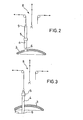
- Fig. 2 den ausgeschwenkten Ofendeckel mit einer Hubvorrichtung, bei der eine der drei Elektroden am Kragennippel erfaßt, in oberer Stellung dargestllt ist,
- Fig. 3 wie Fig. 2, jedoch ist die Elektrode über die Hubvorrichtung in der gewünschten Länge nachgelassen, dargestellt,
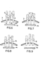
- Fig. 4 den ausgeschwenkten Ofendeckel mit drei unterschiedlich abgebrannten Elektroden, die von einzelnen Stützplatten von unten unterstützt, dargestellt sind,
- Fig. 5 wie Fig. 4, jedoch sind die drei Elektroden um die vorgesehene Länge nachgelassen, indem die Stützplatten mit den aufstehenden Elektrodenspitzen auf die vorgewählte gleiche Höhe abwärts gefahren, dargestellt sind,
- Fig. 6 den ausgeschwenkten Ofendeckel mit unterschiedlich abgebrannten Elektroden und darunter befindlichem Stütztisch,
- Fig. 7 wie Fig. 6, wobei die Elektrodenarme die angeklammerten Elektroden soweit abwärts gefahren haben, bis die Elektrodenspitzen auf dem Stütztisch aufstehen,
- Fig. 8 wie Fig. 7, wobei die Elektroden mit den Spitzen auf dem Stütztisch aufstehen, die Elektrodenklammern gelöst sind und auf gleiches Höhenmaß hochgefahren, dargestellt sind,
- Fig. 9 wie Fig. 8, die Elektrodenarme fahren mit den wieder angeklammerten Elektroden um ein vorgewähltes Maß hoch, damit der Ofendeckel samt Elektroden-Trageeinrichtung bereit zum einschwenken auf das Ofengefäß, dargestellt ist.
- 1 shows an electric arc furnace, consisting of a furnace vessel with the furnace lid swung out and electrodes that have burned up differently in length,
- 2 the swung-out furnace cover with a lifting device, in which one of the three electrodes is gripped on the collar nipple, is shown in the upper position,
- 3 as in FIG. 2, but the electrode has been reduced in the desired length via the lifting device,
- 4 shows the pivoted-out furnace cover with three differently burned electrodes, which are supported by individual support plates from below,
- 5 as in FIG. 4, but the three electrodes have been reduced by the intended length in that the support plates with the rising electrode tips are moved down to the preselected same height,
- 6 the pivoted-out furnace cover with differently burned-off electrodes and a support table underneath,
- 7 as in FIG. 6, the electrode arms having moved the clamped electrodes downwards until the electrode tips stand on the support table,
- 8 like FIG. 7, the electrodes with the tips standing on the support table, the electrode clamps being released and being raised to the same height, are shown,
- Fig. 9 as Fig. 8, the electrode arms move up with the electrodes clipped on again by a preselected amount, so that the furnace lid together with the electrode carrying device is shown ready to be pivoted onto the furnace vessel.
Fig. 1 zeigt das Ofengefäß 1 und den abgeschwenkten Ofendeckel 3 eines Elektro-Lichtbogenofens 2 im Schnitt. In der Absicht, das Verfahren übersichtlich zu erläutern, sind die in Fig. 1 und den folgenden Zeichnungen dargestellten Einrichtungen und Vorrichtungen nur schematisch dargestellt.Fig. 1, the furnace vessel 1 and the pivoted
Das Ofengefäß 1 ist durch einen Ofendeckel 3 verschließbar, welcher durch in der Zeichnung nicht näher veranschaulichte Mittel höhenverstellbar, sowie um eine nicht näher bezeichnete, vertikale Achse in der Horizontalen schwenkbar ist.The furnace vessel 1 can be closed by a
Der Ofendeckel 3 wird von drei um 120° zueinander versetzt angeordneten Elektroden 4 vertikal durchsetzt. Diese Elektroden 4 werden von einer in der Zeichnung nicht näher dargestellten Elektroden-Hub- und -tragevorrichtung über Tragarme bewegt und mittels Elektrodenklammern 5 lösbar umklammert. Die die Elektrodenklammern 5 tragenden Elektroden-Tragearme sind bei ausgeschwenktem Ofendeckel 3 vertikal verlagerbar.The
Zur Erhaltung der zeichnerischen Übersichtlichkeit sind darüber hinaus auch die elektrischen Zuführungen zu den Elektroden 4 über die Elektrodenklammern, die zumeist aus Fassungsring und Kontaktbacken bestehen, in den Zeichnungen nicht näher dargestellt.In order to maintain the clarity of the drawing, the electrical feeds to the
Fig. 1 zeigt die Elektroden 4 nach einer Reihe von Einschmelzvorgängen und es ist ersichtlich, daß bedingt durch unterschiedlichen Abbrand die Elektrodenspitzen 6, 6' und 6'' unterschiedlich abgebrannt sind.Fig. 1 shows the
Beim Nachlaßvorgang werden die Elektroden, die nach dem vorhergehenden Abbrand unterschiedliche Längen aufweisen, nachgelassen, so daß ihre Spitzen dann auf einer Höhe nachgelassen werden, die mit der Linie 7 angezeigt ist.During the releasing process, the electrodes, which have different lengths after the previous erosion, are relieved, so that their tips are then relieved at a height which is indicated by the line 7.
In Fig. 2 und 3 wird das Nachlassen der Elektroden 4 mittels einer Hubvorrichtung 8 bei vollausgeschwenktem Ofendeckel schematisch dargestellt. Die Elektroden 4 werden mit den an ihrem oberen Ende befindlichen Tragenippeln 9 über Aufhängehaken mit der in Elektrodenposition bei ausgeschwenktem Deckel zugeordneten Hubvorrichtung 8 verbunden. Nach dem Lösen der Elektrodenklammern 5 werden die freien Längen der Elektroden 4 auf eine vorwählbare Länge unterhalb der Elektrodenklammern 5 abgesenkt. Die Elektrodenspitzen 6, 6' und 6" werden auf die gleiche Höhe, die der Linie 7 entspricht, abgelassen.2 and 3, the easing of the
Nach dem Wiederanklemmen der Elektrodenklammern 5 wird die Verbindung zur Hubvorrichtung 8 gelöst.After reconnecting the electrode clamps 5, the connection to the
Beim Einsatz dieser Hubvorrichtung ist die Beobachtung und Abstimmung der Höhe der Elektrodenspitzen 6, 6' und 6" etwa in der Höhe der Linie 7 zwar dem Schmelzer überlassen. Der Vorteil ist aber der, daß die Nachlaßlänge der den ausgeschwenkten Ofendeckel durchsetzenden Elektroden frei vom Ofengefäß und ohne thermische Beeinträchtigung des Schmelzers von diesem festgelegt werden kann.When using this lifting device, the observation and coordination of the height of the
Bei dem in Fig. 4 und 5 schematisch dargestellten Verfahren zum Nachlassen der Elektroden ist eine Nachlaßvorrichtung 10 mit drei voneinander unabhängigen Stützplatten 11 und zugehörigen Hubelementen 12 mit Steuerelementen exakt in der Verlängerung der Elektrodenachsen des in der Endstellung ausgeschwenkten Ofendeckels 3 vorgesehen.In the method for releasing the electrodes shown schematically in FIGS. 4 and 5, a releasing
Nachdem der Ofendeckel 3 für das Chargieren in seine Endstellung ausgeschwenkt ist, werden über einzelne Hubelemente 12 die in der Höhe verstellbaren Stützplatten 11 von unten feinfühlig bis zum Kontakt mit den Elektrodenspitzen 6 an diese herangefahren. Sobald die Stützplatten 11 bei ihrer Aufwärtsbewegung die Elektroden berühren und diese tragen, werden die Elektrodenklammern 5 gelöst. Nunmehr werden die Stützplatten 11 mit den Elektroden bei geöffneten Elektrodenklammern 5 bis auf eine festgelegte Stellung, das heißt bis auf die Nachlaßstellung 13 abwärts gefahren, wobei die Stützplatten 11 mit den aufstehenden Elektroden 4 gemeinsam abgesenkt werden. Bei Erreichung der Nachlaßstellung 13 gemäß Fig. 5 werden die Elektrodenklammern 5 wieder angeklemmt. Nach dem Abklemmen der drei Elektrodenklammern werden die Elektrodenarme mit den Elektrodenklammern 5 und den angeklemmten Elektroden in die obere Ausgangstellung zurückgefahren; die Stützplatten 11 werden in die untere Ausgangsstellung zurückgefahren, so daß der Ofendeckel nach Abschluß des Chargievorganges über das Ofengefäß wieder eingeschwenkt werden kann.After the
Da die Elektrodenklammern sich in oberster Position befinden und die Stützplatten 11 mit den Elektroden in die festgelegte Nachlaßstellung 13 gefahren werden, ist die eingestellte Elektrodenlänge A - das heißt der Abstand von den Elektrodenspitzen 6 bis Unterkante Elektrodenklammer 5 bei ausreichend langen Elektroden für jede Schmelze konstant. Die Aufwärtsbewegung der Stützplatten 11 wird gestoppt, sobald ein geringer Druck auf das Nachlaßsystem ansteht, und es ist eine Beschädigung der Elektroden ausgeschlossen.Since the electrode clamps are in the uppermost position and the
Einige Ofenkonstruktionen lassen es zu, daß bei ausgeschwenktem Ofendeckel die Elektrodenarme abwärts gefahren werden können. Bei diesen Ofenkonstruktionen ist es nicht erforderlich, daß Stützplatten in ihrer Höhe verfahrbar sind.Some furnace designs allow the electrode arms to be moved downwards when the furnace lid is swung out. With these furnace designs it is not necessary that the height of the support plates can be moved.
Nachdem der Ofendeckel 3 in seine Endlage ausgeschwenkt worden ist, werden die Elektrodenarme mit den die Elektroden halternden Klammern 5 soweit heruntergefahren, bis die Elektrodenspitzen 6, 6' und 6'' den Stütztisch 14 berühren. Dieses ist in Fig. 6 und 7 schematisch veranschaulicht.After the
Sobald die Elektrodenspitzen 6 mit dem Stütztisch 14 Kontakt bekommen, wird die Abwärtsbewegung der einzelnen Elektrodenarme mit den angeklemmten Elektroden 4 gestoppt und die Elektrodenklammern 5 lösen sich. Nachdem alle drei Elektroden auf dem Stütztisch 14 aufstehen und die Klammern 5 gelöst sind, werden die Elektrodenarme mit den Elektrodenklammern 5 auf eine festgelegte Höhe, die Nachlaßhöhe 15, hochgefahren. Dieses ist in Fig. 8 dargestellt. Anschließend werden die Klammern 5 geschlossen und die Elektrodenarme mit den die Elektroden klammernden Elektrodenklammern werden wieder in die oberste Position gemäß Fig. 9 gefahren. Nunmehr kann nach Abschluß des Chargiervorganges der Ofendeckel 6 wieder eingeschwenkt werden.As soon as the
Die beiden zuletzt beschriebenen Verfahren unterscheiden sich also prinzipiell dadurch, daß gemäß Fig. 4 und 5 die in unterschiedlicher Abbrandhöhe befindlichen Elektrodenspitzen von einzelnen Stützplatten von unten vorsichtig angefahren werden. Im anderen Falle sind die Elektrodenarme bedingt durch eine besondere Ofenkonstruktion geeignet, die Elektroden soweit in die unterste Stellung zu fahren, bis die Elektrodenspitzen durch vorsichtiges Abwärtsfahren auf dem Stütztisch aufsitzen. Es ist natürlich mit eingeschlossen, daß statt dieses für alle Elektroden gemeinsamen Stütztisches auch für jede Elektrode ein in der Höhe fest fixierter Stützteller vorgesehen sein kann.The two methods described last differ in principle in that, according to FIGS. 4 and 5, the electrode tips, which are at different levels of burnup, are carefully approached from below by individual support plates. In the other case, due to a special furnace construction, the electrode arms are suitable for moving the electrodes into the lowest position until the electrode tips sit on the support table by carefully moving them down. It is of course also included that instead of this support table common to all electrodes, a support plate which is firmly fixed in height can also be provided for each electrode.
Auf die zeichnerische Detaildarstellung der Vorrichtungen wird bewußt verzichtet, da beispielsweise sowohl Hydraulikzylinder oder auch motorisch höhenbewegte Stützsäulen zur vorgesehenen, feinfühligen Verlagerung der Stützplatten eingesetzt werden können. Die Vorrichtungen müssen nur die beiden Bedingungen der umschaltbaren Geschwindigkeitsregelung erfüllen. Der Aufwärtshub muß feinfühlig vorgesehen sein mit einem Überlastschalter, der bei Kontakt mit den Elektrodenspitzen den Aufwärtshub stopt. Der automatische Abwärtshub muß auf eine untere Nachlaßstellung 13 begrenzt sein. Für den Fall der nicht mehr voll ausreichenden Elektrodenlänge wird der Abwärtshub von Hand gesteuert.The detailed representation of the devices in the drawing is deliberately omitted, since, for example, both hydraulic cylinders or motor-driven support columns can be used for the intended, sensitive displacement of the support plates. The devices only have to meet the two conditions of the switchable speed control. The upstroke must be delicately provided with an overload switch that stops the upstroke when it comes into contact with the electrode tips. The automatic downward stroke must be limited to a
- 1 Ofengefäß1 oven vessel
- 2 Lichtbogenofen2 arc furnaces
- 3 Ofendeckel3 furnace covers
- 4 Elektroden4 electrodes
- 5 Elektrodenklammern5 electrode clips
- 6 Elektrodenspitzen (6, 6' und 6" )6 electrode tips (6, 6 'and 6 ")
- 7 Linie7 line
- 8 Hubvorrichtung8 lifting device
- 9 Tragenippel9 carrying nipples
- 10 Nachlaßvorrichtung10 release device
- 11 Stützplatte11 support plate
- 12 Hubelement12 lifting element
- 13 Nachlaßstellung13 estate position
- 14 Stütztisch14 support table
- 15 Nachlaßhöhe15 estate amount
Claims (5)
Applications Claiming Priority (2)
| Application Number | Priority Date | Filing Date | Title |
|---|---|---|---|
| DE19803023052 DE3023052A1 (en) | 1980-06-20 | 1980-06-20 | METHOD FOR RELEASING THE ELECTRODES OF AN ELECTRIC ARC FURNACE |
| DE3023052 | 1980-06-20 |
Publications (2)
| Publication Number | Publication Date |
|---|---|
| EP0042609A1 true EP0042609A1 (en) | 1981-12-30 |
| EP0042609B1 EP0042609B1 (en) | 1983-06-22 |
Family
ID=6105024
Family Applications (1)
| Application Number | Title | Priority Date | Filing Date |
|---|---|---|---|
| EP81104756A Expired EP0042609B1 (en) | 1980-06-20 | 1981-06-20 | Process for lowering the electrodes of an electric arc furnace |
Country Status (5)
| Country | Link |
|---|---|
| US (1) | US4399545A (en) |
| EP (1) | EP0042609B1 (en) |
| BR (1) | BR8103910A (en) |
| DE (1) | DE3023052A1 (en) |
| ES (1) | ES503226A0 (en) |
Families Citing this family (5)
| Publication number | Priority date | Publication date | Assignee | Title |
|---|---|---|---|---|
| DE3427904A1 (en) * | 1984-07-28 | 1986-02-06 | M.A.N. Maschinenfabrik Augsburg-Nürnberg AG, 4200 Oberhausen | LIFTING AND LOWERING DEVICE FOR A DEVICE FOR ADJUSTING THE ELECTRODES OF AN ELECTRIC ARC FURNACE AND METHOD FOR OPERATING THE DEVICE |
| US5115447A (en) * | 1991-01-10 | 1992-05-19 | Ucar Carbon Technology Corporation | Arc furnace electrode control |
| CN104122448B (en) * | 2014-07-23 | 2017-04-12 | 上海硅酸盐研究所中试基地 | High-temperature test fixture |
| ITUB20160079A1 (en) * | 2016-01-19 | 2017-07-19 | Fast Tech S R L | POSITIONING DEVICE FOR AT LEAST ONE ELECTRODE FOR FUSER OVENS. |
| CN111886323A (en) * | 2017-10-13 | 2020-11-03 | 加拿大派罗杰尼斯有限公司 | DC electric arc furnace for melting and gasifying wastes |
Citations (6)
| Publication number | Priority date | Publication date | Assignee | Title |
|---|---|---|---|---|
| CH136502A (en) * | 1928-10-26 | 1929-11-15 | Wacker Chemie Gmbh | Method and device for moving the sockets on electrodes of electric ovens. |
| DE568927C (en) * | 1927-12-17 | 1933-01-28 | Schloesser Johann | Moving device for electrodes of electric oven |
| GB598462A (en) * | 1944-10-07 | 1948-02-18 | Asea Ab | Suspending device for the electrodes of electric furnaces |
| DE2121119A1 (en) * | 1971-04-29 | 1972-11-09 | Leybold-Heraeus GmbH & Co KG, 5000 Köln | Electro slag melting electrode replacement - electric sensing positioner device |
| AT311070B (en) * | 1971-10-25 | 1973-10-25 | Inst Elektroswarki Patona | Device for adjusting the plasmatron of a plasma arc furnace |
| DE2522801A1 (en) * | 1975-05-22 | 1976-12-02 | Sueddeutsche Kalkstickstoff | Measuring the length of an electrode inside an electric furnace - by lowering a plummet through it to the unmelted charge beneath |
Family Cites Families (5)
| Publication number | Priority date | Publication date | Assignee | Title |
|---|---|---|---|---|
| DE563262C (en) * | 1932-11-03 | Norske Elektrokemisk Ind As | Method for moving the sockets that are to be supplied with power and at the same time carry only the electrodes of electric ovens | |
| US2365521A (en) * | 1943-02-16 | 1944-12-19 | Swindell Dressler Corp | Electric arc furnace |
| US2485094A (en) * | 1946-09-28 | 1949-10-18 | Askania Regulator Co | Multiple speed control system |
| US3404209A (en) * | 1965-05-25 | 1968-10-01 | Brooke Frank Wharton | Furnace construction and utilization |
| US3823243A (en) * | 1973-10-29 | 1974-07-09 | Phoenix Steel Corp | Apparatus for limiting mast travel in electric furnace system |
-
1980
- 1980-06-20 DE DE19803023052 patent/DE3023052A1/en active Granted
-
1981
- 1981-06-19 ES ES503226A patent/ES503226A0/en active Granted
- 1981-06-20 EP EP81104756A patent/EP0042609B1/en not_active Expired
- 1981-06-22 BR BR8103910A patent/BR8103910A/en unknown
- 1981-06-23 US US06/276,459 patent/US4399545A/en not_active Expired - Fee Related
Patent Citations (6)
| Publication number | Priority date | Publication date | Assignee | Title |
|---|---|---|---|---|
| DE568927C (en) * | 1927-12-17 | 1933-01-28 | Schloesser Johann | Moving device for electrodes of electric oven |
| CH136502A (en) * | 1928-10-26 | 1929-11-15 | Wacker Chemie Gmbh | Method and device for moving the sockets on electrodes of electric ovens. |
| GB598462A (en) * | 1944-10-07 | 1948-02-18 | Asea Ab | Suspending device for the electrodes of electric furnaces |
| DE2121119A1 (en) * | 1971-04-29 | 1972-11-09 | Leybold-Heraeus GmbH & Co KG, 5000 Köln | Electro slag melting electrode replacement - electric sensing positioner device |
| AT311070B (en) * | 1971-10-25 | 1973-10-25 | Inst Elektroswarki Patona | Device for adjusting the plasmatron of a plasma arc furnace |
| DE2522801A1 (en) * | 1975-05-22 | 1976-12-02 | Sueddeutsche Kalkstickstoff | Measuring the length of an electrode inside an electric furnace - by lowering a plummet through it to the unmelted charge beneath |
Also Published As
| Publication number | Publication date |
|---|---|
| DE3023052A1 (en) | 1982-01-14 |
| ES8204268A1 (en) | 1982-05-01 |
| DE3023052C2 (en) | 1987-05-07 |
| EP0042609B1 (en) | 1983-06-22 |
| ES503226A0 (en) | 1982-05-01 |
| BR8103910A (en) | 1982-03-09 |
| US4399545A (en) | 1983-08-16 |
Similar Documents
| Publication | Publication Date | Title |
|---|---|---|
| EP0906161B1 (en) | Shaping machine for sheet-like workpieces, especially for bending the edges of sheet-steel components | |
| DE112012000186T5 (en) | Attachment machine for the air-permeable caps of the disposable cell culture bottle | |
| DE2349767A1 (en) | DEVICE FOR AUTOMATIC APPLICATION OF COVER GLASSES | |
| EP0042609B1 (en) | Process for lowering the electrodes of an electric arc furnace | |
| DE2512613A1 (en) | SUCTION DEVICE FOR CAPTURING AND HANDLING A GENERALLY CUBE-SHAPED BODY | |
| DE2407349A1 (en) | COMPLEX BENDING AND / OR FORMING MACHINE | |
| EP0790086B1 (en) | Method and device for separating and further processing of metal bars | |
| EP0505668B1 (en) | Work table with vacuum clamping | |
| EP0387687B1 (en) | Process and apparatus for regulating the interpolar distance to compensate the anode burning up in electrolysis cells | |
| DE3626888A1 (en) | SUSPENSION DEVICE ON A MELTING FURNACE FOR A FURNACE FOR THE CONTINUOUS PRODUCTION OF SELF-BAKING COAL ELECTRODES | |
| DE2712651B1 (en) | Frame placement station in a system for assembling insulating glass | |
| EP3421392A1 (en) | Shelf access equipment suitable for use in a high-bay warehouse | |
| EP0551828A1 (en) | Individual paring stones lifting device | |
| DE2930026A1 (en) | DEVICE FOR APPLYING SEALING MATERIAL TO A SEALING SURFACE OF A FUNNEL-SHAPED PISTON PART OF A CATHODE JET PIPE | |
| DE2525465B2 (en) | METHOD AND APPARATUS FOR THE SIMULTANEOUS REMOVAL OF SEVERAL CORE PLATES FROM A STACK | |
| DE69838744T2 (en) | DEVICE FOR MAINTAINING PROGRAMMABLE AUTOMATICS | |
| DE1558725B2 (en) | DEVICE FOR REMOVING RETAINING RODS FROM THE SUSPENSION EYES OF CATHODE PLATES | |
| AT407967B (en) | Device for blocking optical lenses, in particular spectacle lenses | |
| DE2230925A1 (en) | Filter press - with sliding mechanism for the filter plates or cloths | |
| DE3427904A1 (en) | LIFTING AND LOWERING DEVICE FOR A DEVICE FOR ADJUSTING THE ELECTRODES OF AN ELECTRIC ARC FURNACE AND METHOD FOR OPERATING THE DEVICE | |
| DE2423240C3 (en) | Method and device for detaching an electrolytically precipitated metal plate from cathodes | |
| DE657083C (en) | Fixed stripping device | |
| AT212556B (en) | Device for centering round workpieces on a clamping axis | |
| DE578475C (en) | Method and device for producing electrolytic coatings | |
| DE2256471C3 (en) | Record presser for a record changer |
Legal Events
| Date | Code | Title | Description |
|---|---|---|---|
| PUAI | Public reference made under article 153(3) epc to a published international application that has entered the european phase |
Free format text: ORIGINAL CODE: 0009012 |
|
| AK | Designated contracting states |
Designated state(s): BE FR GB IT |
|
| ITCL | It: translation for ep claims filed |
Representative=s name: BARZANO' E ZANARDO MILANO S.P.A. |
|
| 17P | Request for examination filed |
Effective date: 19811117 |
|
| ITF | It: translation for a ep patent filed |
Owner name: BARZANO' E ZANARDO MILANO S.P.A. |
|
| GRAA | (expected) grant |
Free format text: ORIGINAL CODE: 0009210 |
|
| AK | Designated contracting states |
Designated state(s): BE FR GB IT |
|
| ET | Fr: translation filed | ||
| PLBE | No opposition filed within time limit |
Free format text: ORIGINAL CODE: 0009261 |
|
| STAA | Information on the status of an ep patent application or granted ep patent |
Free format text: STATUS: NO OPPOSITION FILED WITHIN TIME LIMIT |
|
| PGFP | Annual fee paid to national office [announced via postgrant information from national office to epo] |
Ref country code: FR Payment date: 19840515 Year of fee payment: 4 |
|
| PGFP | Annual fee paid to national office [announced via postgrant information from national office to epo] |
Ref country code: BE Payment date: 19840630 Year of fee payment: 4 |
|
| 26N | No opposition filed | ||
| BERE | Be: lapsed |
Owner name: MASCHINENFABRIK AUGSBURG-NURNBERG A.G. Effective date: 19870630 |
|
| PG25 | Lapsed in a contracting state [announced via postgrant information from national office to epo] |
Ref country code: FR Free format text: LAPSE BECAUSE OF NON-PAYMENT OF DUE FEES Effective date: 19880226 |
|
| GBPC | Gb: european patent ceased through non-payment of renewal fee | ||
| REG | Reference to a national code |
Ref country code: FR Ref legal event code: ST |
|
| PG25 | Lapsed in a contracting state [announced via postgrant information from national office to epo] |
Ref country code: GB Effective date: 19881118 |
|
| PG25 | Lapsed in a contracting state [announced via postgrant information from national office to epo] |
Ref country code: BE Effective date: 19890630 |