EP0040837B1 - Durchfluss-Strömungsmesser mit Ultraschall - Google Patents
Durchfluss-Strömungsmesser mit Ultraschall Download PDFInfo
- Publication number
- EP0040837B1 EP0040837B1 EP81103954A EP81103954A EP0040837B1 EP 0040837 B1 EP0040837 B1 EP 0040837B1 EP 81103954 A EP81103954 A EP 81103954A EP 81103954 A EP81103954 A EP 81103954A EP 0040837 B1 EP0040837 B1 EP 0040837B1
- Authority
- EP
- European Patent Office
- Prior art keywords
- transducer
- transducer body
- flowmeter
- pipeline
- periodicity
- Prior art date
- Legal status (The legal status is an assumption and is not a legal conclusion. Google has not performed a legal analysis and makes no representation as to the accuracy of the status listed.)
- Expired
Links
- 230000005855 radiation Effects 0.000 claims abstract description 29
- 230000010355 oscillation Effects 0.000 claims description 10
- 230000005540 biological transmission Effects 0.000 claims description 9
- 239000000463 material Substances 0.000 claims description 6
- 230000008602 contraction Effects 0.000 claims description 3
- 230000010287 polarization Effects 0.000 abstract description 28
- 238000002604 ultrasonography Methods 0.000 description 16
- 230000005284 excitation Effects 0.000 description 14
- 230000010363 phase shift Effects 0.000 description 7
- 238000000576 coating method Methods 0.000 description 5
- 239000011248 coating agent Substances 0.000 description 4
- 238000010586 diagram Methods 0.000 description 4
- 230000000694 effects Effects 0.000 description 4
- 230000000737 periodic effect Effects 0.000 description 4
- XLYOFNOQVPJJNP-UHFFFAOYSA-N water Substances O XLYOFNOQVPJJNP-UHFFFAOYSA-N 0.000 description 4
- 238000011161 development Methods 0.000 description 3
- 230000018109 developmental process Effects 0.000 description 3
- 230000010339 dilation Effects 0.000 description 3
- 238000005259 measurement Methods 0.000 description 3
- 230000035945 sensitivity Effects 0.000 description 3
- 239000000919 ceramic Substances 0.000 description 2
- 230000001419 dependent effect Effects 0.000 description 2
- 238000013461 design Methods 0.000 description 2
- 230000009467 reduction Effects 0.000 description 2
- 239000007787 solid Substances 0.000 description 2
- 230000006978 adaptation Effects 0.000 description 1
- 230000003321 amplification Effects 0.000 description 1
- 230000015572 biosynthetic process Effects 0.000 description 1
- 239000003990 capacitor Substances 0.000 description 1
- 229910010293 ceramic material Inorganic materials 0.000 description 1
- 238000010276 construction Methods 0.000 description 1
- 230000008878 coupling Effects 0.000 description 1
- 238000010168 coupling process Methods 0.000 description 1
- 238000005859 coupling reaction Methods 0.000 description 1
- 238000000151 deposition Methods 0.000 description 1
- 230000008021 deposition Effects 0.000 description 1
- 230000000916 dilatatory effect Effects 0.000 description 1
- 238000011156 evaluation Methods 0.000 description 1
- 238000002474 experimental method Methods 0.000 description 1
- 238000009434 installation Methods 0.000 description 1
- 230000002452 interceptive effect Effects 0.000 description 1
- 238000004519 manufacturing process Methods 0.000 description 1
- 238000001465 metallisation Methods 0.000 description 1
- 238000003199 nucleic acid amplification method Methods 0.000 description 1
- 230000001902 propagating effect Effects 0.000 description 1
- 230000003252 repetitive effect Effects 0.000 description 1
Images
Classifications
-
- G—PHYSICS
- G01—MEASURING; TESTING
- G01F—MEASURING VOLUME, VOLUME FLOW, MASS FLOW OR LIQUID LEVEL; METERING BY VOLUME
- G01F1/00—Measuring the volume flow or mass flow of fluid or fluent solid material wherein the fluid passes through a meter in a continuous flow
- G01F1/66—Measuring the volume flow or mass flow of fluid or fluent solid material wherein the fluid passes through a meter in a continuous flow by measuring frequency, phase shift or propagation time of electromagnetic or other waves, e.g. using ultrasonic flowmeters
- G01F1/662—Constructional details
-
- G—PHYSICS
- G01—MEASURING; TESTING
- G01F—MEASURING VOLUME, VOLUME FLOW, MASS FLOW OR LIQUID LEVEL; METERING BY VOLUME
- G01F1/00—Measuring the volume flow or mass flow of fluid or fluent solid material wherein the fluid passes through a meter in a continuous flow
- G01F1/66—Measuring the volume flow or mass flow of fluid or fluent solid material wherein the fluid passes through a meter in a continuous flow by measuring frequency, phase shift or propagation time of electromagnetic or other waves, e.g. using ultrasonic flowmeters
- G01F1/667—Arrangements of transducers for ultrasonic flowmeters; Circuits for operating ultrasonic flowmeters
Definitions
- the present invention relates to a flow meter as specified in the preamble of claim 1.
- a flow meter as specified in the preamble of claim 1.
- Such a device is known from US-A-39 64 308.
- Another embodiment is the one in which a transmission body for the ultrasound radiation is inserted obliquely into the tube wall, on the outer end face of which the actual transducer body is attached.
- this transmission body In the area of the inner wall of the pipeline, this transmission body has a surface that continues smoothly on the inner wall of the pipe. With such a transmission body, the radiation refraction effect already mentioned occurs.
- transducer body is attached to a coupling block attached to the outside of the tube wall, the refraction also occurring.
- the two documents US-A-3 891 869 and 3 964308 describe an arrangement with ultrasonic transducers, the respective flat radiation surface of which has a circular cross-section and the surface of the inner tube wall viewed in the direction of the tube axis, i. H. essentially, can continue.
- these transducers In order to be able to emit ultrasound radiation in a direction other than perpendicular, these transducers have such a construction that they essentially emit radiation at a certain selected frequency of the electrical excitation voltage with a directional diagram of a corresponding, and in fact whole, solid angle. The dimension of this solid angle is determined by the structural dimensions of the resonance body of this transducer.
- the invention is based on the provision of such transducers for ultrasound radiation which can transmit or receive ultrasound by themselves in an oblique direction, preferably at an angle of ⁇ ⁇ 45 °.
- the transducers for ultrasound radiation provided for the invention according to the claim character can even be curved to match the inner tube wall. Instead of a curvature of the entire transducer body, a curvature only of the inner surface of this transducer can also be provided.
- This periodic structure can be a polarity in the material of the transducer body that alternates over the length of the transducer body (parallel to the tube axis), the polarization of the transducer body parallel to the thickness of the transducer body being alternately directed antiparallel with this period. Another off.
- An embodiment of the principle of the invention provides an interdigital structure as an electrode arrangement on the surface of the transducer body facing away from the tube interior, this interdigital structure consisting of two interdigitated comb structures, each with fingers and busbar. Such interdigital structures are also known for other purposes from piezoceramic runtime arrangements.
- a particularly advanced solution according to the principle of the invention is a transducer which has both periodically alternating polarization and correspondingly periodically designed interdigital structure on the surface of the transducer body facing away from the tube interior.
- this embodiment of the invention When excited with two alternating voltages which are 90 ° out of phase with one another, this embodiment of the invention, which is embodied in alternating fashion, has a transmission and reception direction at an angle to the surface, but only in one direction.
- the periodicity d according to the above equation applies there to the distance between such next-adjacent fingers, which also includes repetitive polarization.
- Another, particularly advanced solution has a transducer with a double interdigital structure on one side of the transducer body and uniform polarization of the transducer body.
- the excitation takes place with four alternating voltages, each phase-shifted by 90 °, one of which is applied between one of the four comb structures of the double interdigital structure and the common counter electrode on the back.
- This converter also emits only in one direction at an angle ⁇ .
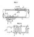
- Fig. 1, 1 denotes the pipe in section, in which the medium to be measured (not shown) flows and through the interior of which ultrasound in a manner known per se with the angle ⁇ from a converter 2 to a converter 3 and for forming the difference between Converter 3 to converter 2 is sent.
- the transducer 2 with a plate-shaped body K made of piezoelectric ceramic is installed in the wall of the tube 1 in such a way that the tube inner wall has the smallest possible interruption in its shape.
- the inside 4 of the body K of the transducer 2 of the tube inner wall can have a corresponding curvature.
- the transducer 2 has on the inside 4 an electrode coating 5 as is usual for piezoceramic components, which is sufficiently resistant to the respective flowing medium or is protected by an acoustically non-interfering coating.
- This electrode coating 5 is preferably electrically conductively connected to the tube as a connecting line.
- an interdigital structure known per se, consisting of two comb structures which interlock with their fingers, the fingers of each comb structure being connected to a busbar in each case.
- the fingers 7 shown in section in FIG. 1 belong to one comb structure and the fingers 8 belong to the other comb structure.
- FIG. 1 shows the diagram of such an interdigital structure 9 with the fingers 7 and 8 of a respective comb structure for better explanation door. With 10 and 10 'the respective fingers 7 or 8 connecting busbars are designated.
- the arrows 11 denote the permanent polarization of the piezoelectric ceramic material of the transducer 2. This direction of polarization can also be directed in the direction of the arrows 11 without the operation of this embodiment according to FIG. 1 changing anything.
- the converter 3 can have exactly the same embodiment as the converter 2.
- the dimension d indicates the periodicity of this interdigital structure. It can be clearly seen that a finger 8 of the other comb structure (8, 10 ') lies between the two adjacent fingers of one comb structure (7, 10).
- a second AC voltage U. 2 created between the connection of the comb structure of the fingers 7 and the counter electrode 5 on the inside an AC voltage U 1 and between the connection 18 of the other comb structure of the fingers 8 and the counter electrode 5, a second AC voltage U. 2 created.
- the two AC voltages U 1 and U 2 have the same ultrasonic transmission frequency and reception frequency of the transducers 2 and 3, have the same amplitude, but are 180 ° out of phase with each other.
- This condition and the above-mentioned angular relationship with the periodicity d provides an ultrasound radiation 12, which is emitted from the body K with a predetermined thickness as shown, with a wavefront that is normal (except for the edge regions) with a flat wavefront as shown.
- the same sharp directional characteristic also applies to the reception behavior of transducers 2 and 3.
- the interdigital structure 9 can also be attached to the inside of the tube on the body of the transducer 2 or 3 (and the counter electrode 5 on the outside). Nice . out. Because of the durability of the transducers 2 and 3, however, the choice of sides for the interdigital structure and counterelectrode shown is preferable.
- FIG. 1 also emits an ultrasound wave in the direction indicated by 12 ', which, however, runs dead in the interior of the pipe and has no useful meaning for the flow measurement according to the invention.
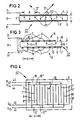
- Fig. 2 shows in an enlarged view only the transducer 22 in its special embodiment for a flow meter, as it is to be installed in the pipe wall instead of a transducer 2 and 3.
- Fig. 2 shows the embodiment with alternating polarization in the body K of the converter 22; 111 and 112 denote the opposite polarization directions of the total polarization of the piezoceramic body K of the transducer 22.
- a periodic structure with the periodicity spacing d (to fulfill the above equation for the radiation at angle a) is carried out by prior polarization with a corresponding grid-shaped electrode.
- a single excitation alternating voltage U ⁇ with the predetermined frequency f is applied between these two electrodes, ie to the connections 71 and 81.
- the periodicity of the polarization 111, 112 ensures the required ultrasound radiation at the angle ⁇ .
- the reception characteristic of such a converter 22 according to FIG. 2 has a corresponding angle ⁇ .
- FIG. 3 again shows an enlarged representation of the special embodiment of a transducer 32 to be used for the invention, which, like the transducers 2 and 3, is to be installed in the pipe wall 1.
- FIG. 4 shows an embodiment of a transducer for a flow meter, in which this transducer 42 has on its one surface a schematically represented double interdigital structure with the periodicity d.
- this transducer 42 has on its one surface a schematically represented double interdigital structure with the periodicity d.
- a full-surface metallization is sufficient as the counter electrode (as in the examples in FIGS. 1 and 3).
- the double interdigital structure 91 consists of a total of four comb structures, each with a busbar 10, 10 ', 10 ", 10"'.
- the two busbars 10 and 10 are located on one edge of the double interdigital structure.
- the busbar 10 has the fingers 7 shown and the busbar 10" includes the fingers 7 'shown.
- the fingers 7 and 7 'of the two comb structures alternate with one another, as can be seen from FIG. 4.
- connection 43, 44, 45 and 46 The connections of the individual comb structures or of the busbars 10 to 10 are denoted by 43, 44, 45 and 46.
- a first alternating voltage U 43 with the intended ultrasonic frequency f is to be applied between the connection 43 and the counter-electrode (not shown) over the entire surface of the rear of the transducer 42.
- a second AC voltage U 44 is to be applied between the connection 44 and the counter electrode mentioned, which has a phase shift of + 43 ° with respect to the voltage U 43 .
- An AC voltage U 45 with a phase shift with respect to U 43 + 180 ° is to be connected between the connection 45 and the counter electrode and an AC voltage U 46 with a phase shift with respect to U 43 + 270 ° is to be connected between the connection 46 and the counter electrode.
- These four AC voltages U 43 to U 46 have the same frequency and the same amplitude.
- the permanent polarization of the body of the transducer 42 is the same in the thickness direction of the same throughout the body and rectified, that is, uniform.
- the converter 42 according to FIG. 4 has the advantage over the converters according to FIGS. 1 to 3 only one radiation direction 12 with the angle ⁇ according to the above equation.
- the further radiation direction shown with dashed lines and denoted by 12 ' is omitted.
- this transducer according to FIG. 4 also has only one-sided reception sensitivity in the direction 12 alone. This transducer is therefore also insensitive to disturbances due to multiply reflected sound which would always be incident in the pipeline from the direction 12 '.
- the omission of the radiation direction 12 ′ leads to a corresponding amplification of the beam 12 with the same electrical AC power output being used and also to a correspondingly increased reception sensitivity.
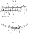
- the transducer 52 in its piezoceramic body K having a periodicity of polarization and, on one side, again preferably the outside 6 of the transducer 52 built into the tube, also an interdigital structure 9 according to FIG. 1a Has.
- the alternating polarization belonging to this interdigital structure 9 is indicated by 211 and 212. It is important to recognize that adjacent fingers 7 or adjacent fingers 8 of one or the other comb structure in the body K of the transducer each have opposite polarization directions 211 and 212, and that only for the second finger 7 or second finger 8 one or the other comb structure again has the same polarization direction 211 or 212.
- the interdigital structure 9 has been adapted to the alternating structure of the polarization indicated, the periodicity d as indicated in FIG. 5.
- the transducer 52 according to FIG. 5 as well as for the transducer 42 according to FIG. 4, this means that there are half as great for otherwise identical conditions with regard to the angle ⁇ , the thickness of the body of the transducer, the excitation frequency f etc.
- the interdigital structure of the transducers 42 and 52 to be produced according to FIG. 4 and therefore requires twice the resolution of the fingers 7, 7 ', 8 and 8'.
- the fingers 7 are connected to one connection and the fingers 8 to a second common connection 54, and to excite the converter 52 there are the two frequency and amplitude-identical alternating voltages U 11 and U 12 , as shown , but U 11 and U 12 (in contrast to FIGS. 1, 1a) need only have a 90 ° phase shift with respect to one another.
- the 90 ° phase shift has the advantage that such a phase shift can be generated electronically in a simple manner with a capacitor.
- the converter 52 according to FIG. 5 also has only one radiation direction 12 with the angle ⁇ according to the above equation, so that what was said about FIG. 4 applies here again.
- FIG. 6 shows a detail view of an adaptation piece 61, as already mentioned above, as is also to be used for the converter 2 (as shown) for all other converters 3, 22, 32, 42 and 52 with a flat converter body with the same advantage.
- the reference number 1 indicates the pipe.
- transducers described Another advantage of the transducers described is that by simply changing the frequency of the excitation alternating voltage (s) U, the radiation angle, ie the angle ⁇ in the direction 12, can be electrically readjusted or controlled. This is not only for inaccurate original installation, but also for, for example, temperature-related changes in the refractive index dex of the flowing medium important. It can in the invention, for. B. a simple automatic tuning to the optima of sending and receiving can be provided. The relationship is optimal with constructively given d and ⁇ . This means that the value of the speed of sound is c - and can be determined from the value f.
- the value c of the speed of sound is required in the final numerical evaluation (known for ultrasonic flow meters) and is obtained here in a simple manner.
- the transducer body is given a thickness t which is equal to half the wavelength of the acoustic wave in the material of the transducer body, which is generated there by electrical excitation with the AC voltage of frequency f, then a thickness resonance oscillation of the transducer body is generated.
- this value for a transducer body with an interdigital structure of polarization and / or the electrodes for a given thickness t of the transducer body is lower than the thickness resonance frequency of a conventional plate-shaped transducer body of the same thickness t without an interdigital structure.
- the value of the thickness t at which this body vibrates in thickness resonance is greater than that for resonance of a conventional plate without such a structure at a predetermined frequency f.
- these transducer bodies with an interdigital structure can be thought of as being composed of strips or adjacent partial volumes that are adjacent in the direction parallel to the finger electrodes or parallel to the stripes of the polarization of this transducer body and that correspond to the alternating electrical excitation or the spatial alternating permanent polarization of the transducer body are expanded accordingly.
- Neighboring partial volumes of the transducer body with an interdigital structure vibrate in opposite phases, i. H.
- a partial volume that is instantaneously contracting in the thickness direction is located between two adjacent partial volumes that are just dilating at this moment, essentially in the direction of the adjacent partial volume that is just contracting.
- the dilation therefore finds a substantially lower internal resistance of the respective neighboring sub-volumes, which is directed against this expansion, which corresponds to a reduction in the stiffness inherent in the material.
- the Poisson's transverse contraction can therefore have a major effect.
- a further embodiment of the invention provides for alternatively generating a resonance vibration of such a vibration mode in the transducer body, in which the variable determining the mechanical resonance frequency is equal to the value d / 2.
- This value d / 2 corresponds to the width of an individual strip with permanent polarization which is in the same direction or with electrical excitation which is in each case in phase.
- Such a strip of width d / 2 can largely be viewed here as a single resonance body.
- the thickness t to be provided for the resonance of a piezoceramic plate can be given mathematically as a function of the frequency f. However, it is much simpler to determine the value of the thickness t or the period d for the predetermined frequency f for the practical application by a simple experiment. A value determined on a single piece then applies to the entire production series. If the thickness t or the dimension d is specified in individual cases, the frequency value f should be varied accordingly until one or the other resonance occurs, for which a corresponding angle IX then results (which then also applies to the arrangement of the second ( Receiving) converter applies.
- a phase shift by 180 ° is inevitably associated with a resonance.
- This is disadvantageous if the excitation frequency and the material and design-related resonance frequency shift from one another or have to be shifted inevitably.
- a shift in the frequency f of the electrical excitation voltage becomes necessary if - in order to maintain a constant angle a - the flowing medium to be measured in the pipeline is replaced, e.g. B. gasoline against oil and / or a change in temperature of the flowing medium occurs.
- the resonance oscillation according to the present invention if the flow meter for a certain medium, e.g. B. only for water, is advantageous, the fact that the fact that the speed of sound in water is relatively little temperature dependent is advantageous.
- Such a flow meter further developed according to the present invention can therefore not only be used advantageously for cold or warm water, but it can also be used with sufficient measuring accuracy for the flow measurement of alternating hot and cold water.
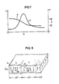
- the diagram of FIG. 7 contains the frequency on the abscissa with the value fo for the resonance frequency.
- the value fo of the resonance frequency corresponds to the selected thickness t or the dimension d / 2 of the transducer body. It is then equal to the frequency of the exciting AC voltage applied to the converter, which frequency is caused by the predetermined angle ⁇ .
- the amplitude A is plotted in arbitrary units on the left ordinate in FIG. 7 and the phase ⁇ is plotted on the right ordinate.
- the frequency-dependent amplitude of the ultrasonic vibration of the transducer body K represents curve A of the diagram and the associated one. Phase shows the curve ⁇ .
- FIG. 7 It can be seen from FIG. 7 what gain in efficiency can be achieved with regard to the generation of ultrasound energy to be emitted. It also shows the possible limits and the effects of a shift in the frequency of the exciting electrical AC voltage in the region of a resonance of the transducer body K.
- FIG. 8 shows a transducer body K as in FIG. 2, but here without the electrodes 5 and 5 '.
- the polarization is indicated at 111 as in FIG. 2. It can be seen that strip or bar-shaped partial volumes a, b, c... Are present adjacent to one another, within which there is uniform polarization 111. For example, the partial volume b the sub-volume A (and the partial volume c) have opposite direction of the permanent Pola - risation 111 has. With electrical excitation by applying the AC voltage to the electrodes 5 and 5 'shown only in FIG. B.
Landscapes
- Physics & Mathematics (AREA)
- Electromagnetism (AREA)
- Fluid Mechanics (AREA)
- General Physics & Mathematics (AREA)
- Measuring Volume Flow (AREA)
- Reciprocating Pumps (AREA)
- Infusion, Injection, And Reservoir Apparatuses (AREA)
- Domestic Plumbing Installations (AREA)
- Indicating Or Recording The Presence, Absence, Or Direction Of Movement (AREA)
Priority Applications (1)
| Application Number | Priority Date | Filing Date | Title |
|---|---|---|---|
| AT81103954T ATE9184T1 (de) | 1980-05-28 | 1981-05-22 | Durchfluss-stroemungsmesser mit ultraschall. |
Applications Claiming Priority (2)
| Application Number | Priority Date | Filing Date | Title |
|---|---|---|---|
| DE3020282A DE3020282C2 (de) | 1980-05-28 | 1980-05-28 | Durchfluß-Strömungsmesser mit Ultraschall |
| DE3020282 | 1980-05-28 |
Publications (2)
| Publication Number | Publication Date |
|---|---|
| EP0040837A1 EP0040837A1 (de) | 1981-12-02 |
| EP0040837B1 true EP0040837B1 (de) | 1984-08-29 |
Family
ID=6103438
Family Applications (1)
| Application Number | Title | Priority Date | Filing Date |
|---|---|---|---|
| EP81103954A Expired EP0040837B1 (de) | 1980-05-28 | 1981-05-22 | Durchfluss-Strömungsmesser mit Ultraschall |
Country Status (6)
| Country | Link |
|---|---|
| US (1) | US4375767A (enExample) |
| EP (1) | EP0040837B1 (enExample) |
| JP (2) | JPS5720614A (enExample) |
| AT (1) | ATE9184T1 (enExample) |
| DE (1) | DE3020282C2 (enExample) |
| DK (1) | DK161259C (enExample) |
Families Citing this family (29)
| Publication number | Priority date | Publication date | Assignee | Title |
|---|---|---|---|---|
| DE3235750C2 (de) * | 1982-09-27 | 1984-12-13 | Endress U. Hauser Gmbh U. Co, 7867 Maulburg | Sensor zur Detektion zufälliger, zur korrelativen Signalverarbeitung geeigneter Signale |
| DE3306529C2 (de) * | 1983-02-24 | 1985-02-14 | Siemens AG, 1000 Berlin und 8000 München | Ultraschallwandler zur Wärmemengenmessung |
| DE3333409A1 (de) * | 1983-09-15 | 1985-04-04 | Siemens AG, 1000 Berlin und 8000 München | Verfahren zur ultraschall-durchflussmessung nach dem dopplerprinzip mit verbesserter ortsaufloesung |
| DE3429099A1 (de) * | 1984-08-07 | 1986-02-20 | Siemens AG, 1000 Berlin und 8000 München | Verfahren zur messung der stroemungsgeschwindigkeit v eines fluids nach dem prinzip der phasen-nachregelung und differenzfrequenz-auswertung |
| US4735097A (en) * | 1985-08-12 | 1988-04-05 | Panametrics, Inc. | Method and apparatus for measuring fluid characteristics using surface generated volumetric interrogation signals |
| GB2187552B (en) * | 1986-03-05 | 1990-07-11 | Gen Electric Plc | Apparatus for monitoring movement of a fluid |
| NL8602458A (nl) * | 1986-09-29 | 1988-04-18 | Rheometron Ag | Ultrasone stromingsmeter. |
| DE3633306A1 (de) * | 1986-09-30 | 1988-03-31 | Siemens Ag | Schaltungsanordnung fuer ultraschall-durchflussmesser |
| JPS63188524U (enExample) * | 1987-05-28 | 1988-12-02 | ||
| FI900511A7 (fi) * | 1987-08-10 | 1990-02-01 | Siemens Ag | Ultraääni-virtaamamittauslaite |
| US5540230A (en) * | 1994-04-15 | 1996-07-30 | Echocath, Inc. | Diffracting doppler-transducer |
| US5488953A (en) * | 1994-04-15 | 1996-02-06 | Ecocath, Inc. | Diffracting doppler-transducer |
| DE4416367C1 (de) * | 1994-05-04 | 1995-12-21 | Gerd Prof Dr Stange | Ultraschall-Durchfluß-Meßgerät |
| GB2301186A (en) * | 1995-05-23 | 1996-11-27 | Smith Meters Ltd | Ultrasonic flow meter |
| US6189389B1 (en) | 1996-05-28 | 2001-02-20 | Krohne A.G. | Ultrasonic flowmeter |
| JP3306029B2 (ja) * | 1999-07-27 | 2002-07-24 | サーパス工業株式会社 | 超音波流量計及びその製造方法 |
| US6609430B1 (en) * | 2000-05-09 | 2003-08-26 | Shrinivas G. Joshi | Low profile transducer for flow meters |
| DE10034474C1 (de) * | 2000-07-15 | 2001-10-11 | Flexim Flexible Industriemeste | Verfahren und Vorrichtung zur Charakterisierung eines Fluides oder Gases mittels Ultraschall |
| US6826965B1 (en) * | 2000-10-30 | 2004-12-07 | Panametrics, Inc. | Anti-parallel tag flow measurement system |
| DE50114227D1 (de) * | 2000-11-30 | 2008-09-25 | Landis & Gyr Gmbh | Ultraschallwandler und ultraschall-durchflussmesser |
| EP1350077B1 (de) * | 2001-01-09 | 2006-11-22 | Landis+Gyr GmbH | Durchflussmesser |
| US6637268B1 (en) * | 2002-05-20 | 2003-10-28 | Kohji Toda | Vibration displacement sensing system |
| US6640631B1 (en) * | 2002-05-20 | 2003-11-04 | Kohji Toda | System and measuring sound velocity in material |
| US7658114B1 (en) | 2008-11-17 | 2010-02-09 | General Electric Company | Ultrasonic flow meter |
| US8974606B2 (en) | 2011-05-09 | 2015-03-10 | Intermolecular, Inc. | Ex-situ cleaning assembly |
| US9678091B2 (en) * | 2012-10-02 | 2017-06-13 | Stamford Scientific International, Inc. | In situ monitoring for wastewater treatment systems and the like |
| FR3047068B1 (fr) | 2016-01-25 | 2019-07-19 | Integra Metering Sas | Dispositif de montage d'un transducteur a ultrasons et debitmetre equipe d'un tel dispositif |
| DE102018008393A1 (de) * | 2018-10-24 | 2020-04-30 | Diehl Metering Gmbh | Verfahren und Messeinrichtung zur Ermittlung einer Fluidgröße |
| CN113476739B (zh) * | 2021-06-07 | 2022-11-08 | 浙江迪远医疗器械有限公司 | 具有检测装置的血液泵 |
Family Cites Families (5)
| Publication number | Priority date | Publication date | Assignee | Title |
|---|---|---|---|---|
| SU422958A1 (ru) * | 1972-04-13 | 1974-04-05 | В. И. Домаркас, А. П. Машонис , А. И. Петраускас Каунасский политехнический институт | Ультразвуковой расходомер |
| US3964308A (en) * | 1973-09-04 | 1976-06-22 | Scarpa Laboratories, Inc. | Ultrasonic flowmeter |
| US3891869A (en) * | 1973-09-04 | 1975-06-24 | Scarpa Lab Inc | Piezoelectrically driven ultrasonic generator |
| JPS535429U (enExample) * | 1976-06-30 | 1978-01-18 | ||
| JPS56157861A (en) * | 1980-05-09 | 1981-12-05 | Tdk Corp | Measuring system for velocity of flow of fluid |
-
1980
- 1980-05-28 DE DE3020282A patent/DE3020282C2/de not_active Expired
-
1981
- 1981-05-22 AT AT81103954T patent/ATE9184T1/de active
- 1981-05-22 EP EP81103954A patent/EP0040837B1/de not_active Expired
- 1981-05-27 DK DK233581A patent/DK161259C/da not_active IP Right Cessation
- 1981-05-27 US US06/267,567 patent/US4375767A/en not_active Expired - Fee Related
- 1981-05-28 JP JP8177581A patent/JPS5720614A/ja active Pending
-
1987
- 1987-12-18 JP JP1987193390U patent/JPS63111619U/ja active Pending
Also Published As
| Publication number | Publication date |
|---|---|
| US4375767A (en) | 1983-03-08 |
| DK161259C (da) | 1991-12-30 |
| DE3020282A1 (de) | 1981-12-03 |
| DK161259B (da) | 1991-06-17 |
| JPS5720614A (en) | 1982-02-03 |
| DE3020282C2 (de) | 1985-08-08 |
| EP0040837A1 (de) | 1981-12-02 |
| DK233581A (da) | 1981-11-29 |
| ATE9184T1 (de) | 1984-09-15 |
| JPS63111619U (enExample) | 1988-07-18 |
Similar Documents
| Publication | Publication Date | Title |
|---|---|---|
| EP0040837B1 (de) | Durchfluss-Strömungsmesser mit Ultraschall | |
| DE102019110514B4 (de) | Fluidmesseinrichtung | |
| EP0303255B1 (de) | Ultraschall-Durchflussmesseinrichtung | |
| DE68925093T2 (de) | Torsionswellenfühler und System für Flüssigkeiten | |
| DE3687772T2 (de) | Geraet zur messung der charakteristiken fliessfaehiger stoffe unter verwendung oberflaechenerzeugter volumenuntersuchungssignale. | |
| EP3577427B1 (de) | Ultraschallzähler und verfahren zur erfassung einer durchflussgrösse | |
| DE102015107750A1 (de) | Meßsystem zum Messen wenigstens eines Parameters eines Fluids | |
| DE1805834B2 (de) | Wellenleiteranordnung fuer elastische wellen | |
| DE1958235A1 (de) | Verfahren und Geraet zur Messung von Stroemungen in Leitungen | |
| EP0684457A2 (de) | Ultraschall-Durchfluss-Messgerät | |
| DE2418958A1 (de) | Wandlergitter fuer elastische oberflaechenwellen sowie akusto-optisches ablenkglied oder frequenzselektives uebertragungssystem mit einem solchen wandlergitter | |
| WO2012120039A2 (de) | Verfahren zur ultraschall-clamp-on-durchflussmessung und vorrichtung zur umsetzung des verfahrens | |
| DE102017006173A1 (de) | Messeinrichtung und Verfahren zur Ermittlung einer Fluidgröße | |
| EP3421945B1 (de) | Verfahren und messeinrichtung zur ermittlung einer fluidgrösse | |
| DE10137679C1 (de) | Verfahren und Vorrichtung zur Ermittlung akustischer Parameter von Flüssigkeiten | |
| EP0138017B1 (de) | Verfahren zur Ultraschall-Durchflussmessung nach dem Dopplerprinzip mit verbesserter Ortsauflösung | |
| DE102018005540B4 (de) | 1D-Ultraschallwandler-Einheit | |
| EP1337998B1 (de) | Ultraschallwandler und ultraschall-durchflussmesser | |
| DE4441225C2 (de) | Massendurchfluß-Meßgerät | |
| DE102020126021A1 (de) | Fluidmesseinrichtung | |
| DE102018006127A1 (de) | 1D-Ultraschallwandler-Einheit für die Materialerfassung | |
| DE102021133898A1 (de) | Fluidmesseinrichtung | |
| EP3910295B1 (de) | Messeinrichtung zur ermittlung einer fluidgrösse | |
| DE3120541A1 (de) | Verbesserung eines durchfluss-stroemungsmessers mit ultraschall | |
| DE102009046862A1 (de) | Koppelelement eines Sensors eines Ultraschall-Durchflussmessgeräts |
Legal Events
| Date | Code | Title | Description |
|---|---|---|---|
| PUAI | Public reference made under article 153(3) epc to a published international application that has entered the european phase |
Free format text: ORIGINAL CODE: 0009012 |
|
| AK | Designated contracting states |
Designated state(s): AT CH FR GB IT NL SE |
|
| 17P | Request for examination filed |
Effective date: 19811030 |
|
| ITF | It: translation for a ep patent filed | ||
| GRAA | (expected) grant |
Free format text: ORIGINAL CODE: 0009210 |
|
| AK | Designated contracting states |
Designated state(s): AT CH FR GB IT LI NL SE |
|
| REF | Corresponds to: |
Ref document number: 9184 Country of ref document: AT Date of ref document: 19840915 Kind code of ref document: T |
|
| ET | Fr: translation filed | ||
| PLBE | No opposition filed within time limit |
Free format text: ORIGINAL CODE: 0009261 |
|
| STAA | Information on the status of an ep patent application or granted ep patent |
Free format text: STATUS: NO OPPOSITION FILED WITHIN TIME LIMIT |
|
| 26N | No opposition filed | ||
| PGFP | Annual fee paid to national office [announced via postgrant information from national office to epo] |
Ref country code: AT Payment date: 19910424 Year of fee payment: 11 |
|
| ITTA | It: last paid annual fee | ||
| PGFP | Annual fee paid to national office [announced via postgrant information from national office to epo] |
Ref country code: NL Payment date: 19910531 Year of fee payment: 11 |
|
| PGFP | Annual fee paid to national office [announced via postgrant information from national office to epo] |
Ref country code: CH Payment date: 19910823 Year of fee payment: 11 |
|
| PG25 | Lapsed in a contracting state [announced via postgrant information from national office to epo] |
Ref country code: AT Effective date: 19920522 |
|
| PG25 | Lapsed in a contracting state [announced via postgrant information from national office to epo] |
Ref country code: LI Effective date: 19920531 Ref country code: CH Effective date: 19920531 |
|
| PG25 | Lapsed in a contracting state [announced via postgrant information from national office to epo] |
Ref country code: NL Effective date: 19921201 |
|
| NLV4 | Nl: lapsed or anulled due to non-payment of the annual fee | ||
| REG | Reference to a national code |
Ref country code: CH Ref legal event code: PL |
|
| PGFP | Annual fee paid to national office [announced via postgrant information from national office to epo] |
Ref country code: SE Payment date: 19940526 Year of fee payment: 14 |
|
| EAL | Se: european patent in force in sweden |
Ref document number: 81103954.4 |
|
| PG25 | Lapsed in a contracting state [announced via postgrant information from national office to epo] |
Ref country code: SE Effective date: 19950523 |
|
| EUG | Se: european patent has lapsed |
Ref document number: 81103954.4 |
|
| PGFP | Annual fee paid to national office [announced via postgrant information from national office to epo] |
Ref country code: GB Payment date: 19980414 Year of fee payment: 18 |
|
| PGFP | Annual fee paid to national office [announced via postgrant information from national office to epo] |
Ref country code: FR Payment date: 19980529 Year of fee payment: 18 |
|
| PG25 | Lapsed in a contracting state [announced via postgrant information from national office to epo] |
Ref country code: GB Free format text: LAPSE BECAUSE OF NON-PAYMENT OF DUE FEES Effective date: 19990522 |
|
| GBPC | Gb: european patent ceased through non-payment of renewal fee |
Effective date: 19990522 |
|
| PG25 | Lapsed in a contracting state [announced via postgrant information from national office to epo] |
Ref country code: FR Free format text: LAPSE BECAUSE OF NON-PAYMENT OF DUE FEES Effective date: 20000131 |
|
| REG | Reference to a national code |
Ref country code: FR Ref legal event code: ST |