EP0040834A1 - Folding box - Google Patents
Folding box Download PDFInfo
- Publication number
- EP0040834A1 EP0040834A1 EP81103935A EP81103935A EP0040834A1 EP 0040834 A1 EP0040834 A1 EP 0040834A1 EP 81103935 A EP81103935 A EP 81103935A EP 81103935 A EP81103935 A EP 81103935A EP 0040834 A1 EP0040834 A1 EP 0040834A1
- Authority
- EP
- European Patent Office
- Prior art keywords
- folding box
- walls
- edge
- mirror
- side walls
- Prior art date
- Legal status (The legal status is an assumption and is not a legal conclusion. Google has not performed a legal analysis and makes no representation as to the accuracy of the status listed.)
- Withdrawn
Links
Images


Classifications
-
- B—PERFORMING OPERATIONS; TRANSPORTING
- B65—CONVEYING; PACKING; STORING; HANDLING THIN OR FILAMENTARY MATERIAL
- B65D—CONTAINERS FOR STORAGE OR TRANSPORT OF ARTICLES OR MATERIALS, e.g. BAGS, BARRELS, BOTTLES, BOXES, CANS, CARTONS, CRATES, DRUMS, JARS, TANKS, HOPPERS, FORWARDING CONTAINERS; ACCESSORIES, CLOSURES, OR FITTINGS THEREFOR; PACKAGING ELEMENTS; PACKAGES
- B65D5/00—Rigid or semi-rigid containers of polygonal cross-section, e.g. boxes, cartons or trays, formed by folding or erecting one or more blanks made of paper
- B65D5/20—Rigid or semi-rigid containers of polygonal cross-section, e.g. boxes, cartons or trays, formed by folding or erecting one or more blanks made of paper by folding-up portions connected to a central panel from all sides to form a container body, e.g. of tray-like form
- B65D5/2014—Rigid or semi-rigid containers of polygonal cross-section, e.g. boxes, cartons or trays, formed by folding or erecting one or more blanks made of paper by folding-up portions connected to a central panel from all sides to form a container body, e.g. of tray-like form the central panel having a non rectangular shape
- B65D5/2033—Rigid or semi-rigid containers of polygonal cross-section, e.g. boxes, cartons or trays, formed by folding or erecting one or more blanks made of paper by folding-up portions connected to a central panel from all sides to form a container body, e.g. of tray-like form the central panel having a non rectangular shape polygonal having more than four sides, e.g. hexagonal, octogonal
-
- B—PERFORMING OPERATIONS; TRANSPORTING
- B65—CONVEYING; PACKING; STORING; HANDLING THIN OR FILAMENTARY MATERIAL
- B65D—CONTAINERS FOR STORAGE OR TRANSPORT OF ARTICLES OR MATERIALS, e.g. BAGS, BARRELS, BOTTLES, BOXES, CANS, CARTONS, CRATES, DRUMS, JARS, TANKS, HOPPERS, FORWARDING CONTAINERS; ACCESSORIES, CLOSURES, OR FITTINGS THEREFOR; PACKAGING ELEMENTS; PACKAGES
- B65D5/00—Rigid or semi-rigid containers of polygonal cross-section, e.g. boxes, cartons or trays, formed by folding or erecting one or more blanks made of paper
- B65D5/20—Rigid or semi-rigid containers of polygonal cross-section, e.g. boxes, cartons or trays, formed by folding or erecting one or more blanks made of paper by folding-up portions connected to a central panel from all sides to form a container body, e.g. of tray-like form
- B65D5/2004—Rigid or semi-rigid containers of polygonal cross-section, e.g. boxes, cartons or trays, formed by folding or erecting one or more blanks made of paper by folding-up portions connected to a central panel from all sides to form a container body, e.g. of tray-like form the container body having hollow side-walls
- B65D5/2009—Rigid or semi-rigid containers of polygonal cross-section, e.g. boxes, cartons or trays, formed by folding or erecting one or more blanks made of paper by folding-up portions connected to a central panel from all sides to form a container body, e.g. of tray-like form the container body having hollow side-walls all formed by folding extensions of the side walls
-
- B—PERFORMING OPERATIONS; TRANSPORTING
- B65—CONVEYING; PACKING; STORING; HANDLING THIN OR FILAMENTARY MATERIAL
- B65D—CONTAINERS FOR STORAGE OR TRANSPORT OF ARTICLES OR MATERIALS, e.g. BAGS, BARRELS, BOTTLES, BOXES, CANS, CARTONS, CRATES, DRUMS, JARS, TANKS, HOPPERS, FORWARDING CONTAINERS; ACCESSORIES, CLOSURES, OR FITTINGS THEREFOR; PACKAGING ELEMENTS; PACKAGES
- B65D5/00—Rigid or semi-rigid containers of polygonal cross-section, e.g. boxes, cartons or trays, formed by folding or erecting one or more blanks made of paper
- B65D5/20—Rigid or semi-rigid containers of polygonal cross-section, e.g. boxes, cartons or trays, formed by folding or erecting one or more blanks made of paper by folding-up portions connected to a central panel from all sides to form a container body, e.g. of tray-like form
- B65D5/2095—Rigid or semi-rigid containers of polygonal cross-section, e.g. boxes, cartons or trays, formed by folding or erecting one or more blanks made of paper by folding-up portions connected to a central panel from all sides to form a container body, e.g. of tray-like form a part of the folded-up portions defining an inwardly folded ledge at the edges of the central panel
-
- B—PERFORMING OPERATIONS; TRANSPORTING
- B65—CONVEYING; PACKING; STORING; HANDLING THIN OR FILAMENTARY MATERIAL
- B65D—CONTAINERS FOR STORAGE OR TRANSPORT OF ARTICLES OR MATERIALS, e.g. BAGS, BARRELS, BOTTLES, BOXES, CANS, CARTONS, CRATES, DRUMS, JARS, TANKS, HOPPERS, FORWARDING CONTAINERS; ACCESSORIES, CLOSURES, OR FITTINGS THEREFOR; PACKAGING ELEMENTS; PACKAGES
- B65D5/00—Rigid or semi-rigid containers of polygonal cross-section, e.g. boxes, cartons or trays, formed by folding or erecting one or more blanks made of paper
- B65D5/20—Rigid or semi-rigid containers of polygonal cross-section, e.g. boxes, cartons or trays, formed by folding or erecting one or more blanks made of paper by folding-up portions connected to a central panel from all sides to form a container body, e.g. of tray-like form
- B65D5/22—Rigid or semi-rigid containers of polygonal cross-section, e.g. boxes, cartons or trays, formed by folding or erecting one or more blanks made of paper by folding-up portions connected to a central panel from all sides to form a container body, e.g. of tray-like form held erect by extensions of one or more sides being doubled-over to enclose extensions of adjacent sides
-
- B—PERFORMING OPERATIONS; TRANSPORTING
- B65—CONVEYING; PACKING; STORING; HANDLING THIN OR FILAMENTARY MATERIAL
- B65D—CONTAINERS FOR STORAGE OR TRANSPORT OF ARTICLES OR MATERIALS, e.g. BAGS, BARRELS, BOTTLES, BOXES, CANS, CARTONS, CRATES, DRUMS, JARS, TANKS, HOPPERS, FORWARDING CONTAINERS; ACCESSORIES, CLOSURES, OR FITTINGS THEREFOR; PACKAGING ELEMENTS; PACKAGES
- B65D5/00—Rigid or semi-rigid containers of polygonal cross-section, e.g. boxes, cartons or trays, formed by folding or erecting one or more blanks made of paper
- B65D5/20—Rigid or semi-rigid containers of polygonal cross-section, e.g. boxes, cartons or trays, formed by folding or erecting one or more blanks made of paper by folding-up portions connected to a central panel from all sides to form a container body, e.g. of tray-like form
- B65D5/28—Rigid or semi-rigid containers of polygonal cross-section, e.g. boxes, cartons or trays, formed by folding or erecting one or more blanks made of paper by folding-up portions connected to a central panel from all sides to form a container body, e.g. of tray-like form with extensions of sides permanently secured to adjacent sides, with sides permanently secured together by adhesive strips, or with sides held in place solely by rigidity of material
Definitions
- the present invention relates to a folding box consisting of a lower part and an upper part, in which at least one part is made from a one-piece blank and has a protruding edge.
- a protruding edge on one or both parts of the folding box serves the purpose of giving the folding box an optically larger picture.
- a folding box with a projection edge looks more solid and stable than a folding box with smooth side walls.
- Folding boxes of this type are primarily used for the packaging of chocolates or similar products, but their use is not restricted to this.
- a known method of equipping a folding box with a projection edge is to glue an additional layer of material on the mirror of the box part which is to be equipped with the projection edge, the base area of which is larger than the mirror.
- the layer of material to be glued is lined a little, so that the box part appears somewhat spherical.
- edge of the projection is very unstable, since in the previously known constructions the two layers of material forming the edge of the projection have been placed flat on top of one another and glued together. Despite the double-layered in the region of Vorstehrandes this tends to distortions under load, so that such a folded box does not give the high quality impression one would expect from a folding box with a Vorstehrand. This is also the reason why the previously known folding boxes with one-piece cut and projection edge have not become established in practice.
- the present invention has for its object to design a folding box of the generic type so that despite using a one-piece blank for the equipped with the front edge Box part a permanent, high stability in the area of the projection edge is achieved.
- the mirror of the part provided with the projection edge is connected on all sides exclusively via grooves to the projection edge walls, which are also connected via grooves to the side wall parts standing at right angles to the mirror and with the mirror an acute angle lock in.
- a folding box according to the present invention can be compared both visually and in terms of its overall stability with such a folding box, in which a lined additional material layer is used to achieve a protruding edge.
- the folding box 1 shown in FIGS. 1 to 3 consists of a lower part 2 and an upper part 3.
- the lower part 2 is equipped with a circumferential projection edge 4 and made from a one-piece blank 5 according to FIG. 4.
- the upper part 3 which is also made from a one-piece blank, is equipped with conically tapering side walls.
- the Vorstehrandwandungen 8 are in turn connected to the side walls 10 via grooves 9.
- a stabilizing wall 11 is connected to each of the two longer side walls 10.
- Corner locking tongues 12 are connected to the end faces of the longer projection edge walls 8 and 10 adhesive tabs 13 are connected to the end faces of the longer side walls 10.
- the blank 5 according to FIG. 4 is set up in such a way that the projection edge walls 8 form an acute angle with the floor mirror 6 and merge into the side walls 10 standing at right angles to the floor mirror 6.
- the stabilization walls 11 connected to the longer side walls 10 are bent inwards and preferably glued to the side walls 10.
- corner locking tongues 12 ensure that the circumferential, conical projection edge 4 is properly sealed in the region of its corners 14.
- the side walls 10 adjacent in the corner area are connected to one another by gluing.
- the height of the stabilizing walls 11 corresponds to the clear height of the lower part 2.
- the bottom part 2 set up from the blank 5 according to FIG. 4 is thus equipped with a peripheral projection edge 4 tapering towards the side walls 10, the two adjacent material layers (edge region of the bottom mirror 6 and projection edge walls 8) being connected to one another exclusively via the grooves 7 are. Due to the conicity of the circumferential projection edge 4, an enormous stability of the lower part 2 is achieved overall and in particular in the area of the projection edge 4. This stability is further improved by the attachment of the stabilizing walls 11.
- stabilizing walls 11 can be dispensed with in the case of relatively small dimensions of a folding box. In the case of larger box dimensions, on the other hand, the attachment of stabilizing walls 11 to all side walls 10 can be expedient.
- a folding box lower part 15 which has a polygonal plan.
- This lower part of the folding box 15 is also equipped with a circumferential, conical projection edge 4, the projection wall walls 8 being connected to the floor mirror 6 exclusively via grooves 7.
- the side walls 10a, which are at right angles to the floor mirror 6, are each glued to one another via corner flaps 16.
- Edge tabs 17 which are bent inwards are connected to the free ends of the side walls 10a.
- the folding box lower part 15 according to FIG. 5 also has a very high stability and dimensional stability, in particular in the area of the peripheral projection edge 4, although it has been produced from a one-piece blank.
Abstract
Description
Die vorliegende Erfindung betrifft eine Faltschachtel, bestehend aus einem Unterteil und einem Oberteil, bei der mindestens ein Teil aus einem einstückigen Zuschnitt gefertigt ist und einen Vorstehrand aufweist.The present invention relates to a folding box consisting of a lower part and an upper part, in which at least one part is made from a one-piece blank and has a protruding edge.
Faltschachteln der vorerwähnten Art sind an sich bekannt.Folding boxes of the aforementioned type are known per se.
Die Anbringung eines Vorstehrandes an einem oder an beiden Teilen der Faltschachtel dient dem Zweck, der Faltschachtel ein optisch größeres Bild zu geben. Ausserdem wirkt eine Faltschachtel mit Vorstehrand gediegener und stabiler als eine Faltschachtel mit glatten Seitenwandungen.The attachment of a protruding edge on one or both parts of the folding box serves the purpose of giving the folding box an optically larger picture. In addition, a folding box with a projection edge looks more solid and stable than a folding box with smooth side walls.
Derartige Faltschachteln werden in erster Linie für die Verpackung von Pralinen oder ähnlichen Produkten verwendet, allerdings ist ihr Einsatz nicht darauf beschränkt.Folding boxes of this type are primarily used for the packaging of chocolates or similar products, but their use is not restricted to this.
Eine bekannte Methode, eine Faltschachtel mit einem Vorstehrand auszustatten, besteht darin, auf den Spiegel des Schachtelteiles, welches mit dem Vorstehrand ausgestattet werden soll, eine zusätzliche Materiallage aufzukleben, deren Grundfläche größer ist als der Spiegel. In vielen Fällen wird die aufzuklebende Materiallage etwas ausgefüttert, so daß das Schachtelteil etwas ballig wirkt.A known method of equipping a folding box with a projection edge is to glue an additional layer of material on the mirror of the box part which is to be equipped with the projection edge, the base area of which is larger than the mirror. In many cases, the layer of material to be glued is lined a little, so that the box part appears somewhat spherical.
Diese Methode ist naturgemäß relativ teuer, da einerseits zusätzliches Material benötigt und andererseits ein zusätzlicher Arbeitsgang gegenüber der Herstellung einer einstückigen Faltschachtel benötigt wird.Naturally, this method is relatively expensive because, on the one hand, additional material is required and, on the other hand, an additional operation is required compared to the production of a one-piece folding box.
Es ist auch schon bekannt, ein mit Vorstehrand versehenes Schachtelteil aus einem einstückigen Zuschnitt herzustellen und mit Vorstehrand auszustatten.It is also known to produce a box part provided with a protruding edge from a one-piece blank and to equip it with a protruding edge.
Allerdings ist bei den bekannten Konstruktionen der Vorstehrand sehr instabil, da bei den vorbekannten Konstruktionen die den Vorstehrand bildenden beiden Materiallagen flach aufeinandergelegt und miteinander verklebt worden sind. Trotz der Doppellagigkeit im Bereich des Vorstehrandes neigt dieser zu Verwerfungen unter Belastung, so daß eine derartige Faltschach- tel nicht den qualitativ hochwertigen Eindruck macht, den manasich von einer Faltschachtel mit Vorstehrand erwartet. Dies ist auch der Grund, weshalb sich die vorbekannten Faltschachteln mit einstückigem-Zuschnitt und Vorstehrand in der Praxis nicht durchgesetzt haben.However, in the known constructions the edge of the projection is very unstable, since in the previously known constructions the two layers of material forming the edge of the projection have been placed flat on top of one another and glued together. Despite the double-layered in the region of Vorstehrandes this tends to distortions under load, so that such a folded box does not give the high quality impression one would expect from a folding box with a Vorstehrand. This is also the reason why the previously known folding boxes with one-piece cut and projection edge have not become established in practice.
Der vorliegenden Erfindung liegt die Aufgabe zugrunde, eine Faltschachtel der gattungsgemäßen Art so zu gestalten, daß trotz Verwendung eines einstückigen Zuschnittes für das mit dem Vorstehrand ausgestattete Schachtelteil eine bleibende, hohe Stabilität im Bereich des Vorstehrandes erzielt wird.The present invention has for its object to design a folding box of the generic type so that despite using a one-piece blank for the equipped with the front edge Box part a permanent, high stability in the area of the projection edge is achieved.
Die Lösung dieser Aufgabe besteht nach der Erfindung darin, daß der Spiegel des mit dem Vorstehrand versehenen Teiles allseitig ausschließlich über Rillungen mit den Vorstehrandwandungen verbunden ist, die andererseits ebenfalls über Rillungen mit den rechtwinklig zum Spiegel stehenden Seitenwandteilen verbunden sind und mit dem Spiegel einen spitzen Winkel einschliessen.The solution to this problem is according to the invention that the mirror of the part provided with the projection edge is connected on all sides exclusively via grooves to the projection edge walls, which are also connected via grooves to the side wall parts standing at right angles to the mirror and with the mirror an acute angle lock in.
Bedingt durch die Tatsache, daß im Bereich des Vorstehrandes die einander benachbarten Materiallagen nicht flach aufeinanderliegen, sondern unter einem bestimmten Winkel zueinander verlaufen, wird ein umlaufender, konischer Vorstehrand geschaffen, dessen Stabilität und Formsteifigkeit überraschend hoch ist. Eine Faltschachtel gemäß der vorliegenden Erfindung ist sowohl in optischer Hinsicht wie auch im Hinblick auf ihre Gesamtstabilität durchaus mit einer solchen Faltschachtel vergleichbar, bei der zur Erzielung eines Vorstehrandes eine gefütterte zusätzliche Ma- ter_iallage verwendet wird.Due to the fact that the adjacent material layers do not lie flat on top of each other in the area of the projection edge, but run at a certain angle to each other, a circumferential, conical projection edge is created, the stability and stiffness of which is surprisingly high. A folding box according to the present invention can be compared both visually and in terms of its overall stability with such a folding box, in which a lined additional material layer is used to achieve a protruding edge.
Weitere Merkmale der Erfindung sind Gegenstand von Unteransprüchen.Further features of the invention are the subject of dependent claims.
In den beigefügten Zeichnungen sind Ausführungsbeispiele der Erfindung dargestellt, die im nachfolgenden ausführlich beschrieben werden. Es zeigen:
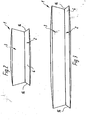
- Fig. 1 eine perspektivische Darstellung einer rechteckigen Faltschachatel nach der Erfindung,
- Fig. 2 eine Ansicht in Richtung des Pfeiles II in Fig. 1,
- Fig. 3 eine Ansicht in Richtung des Pfeiles III in Fig. 1,
- Fig. 4 den Zuschnitt des Faltschachtel-Unterteils der Faltschachtel nach den Fig. 1 bis 3,
- Fig. 5 eine perspektivische Darstellung eines Faltschachtel-Unterteils nach einem weiteren Ausführungsbeispiel der Erfindung,
- Fig. 6 einen Schnitt durch das Faltschachtel-Unterteil der Faltschachtel nach den Fig. 1 bis 3 im Bereich seiner Schmalseite,
- Fig. 7 einen der Fig. 6 entsprechenden Schnitt im Bereich der Längsseiten.
- 1 is a perspective view of a rectangular folding box according to the invention,
- 2 is a view in the direction of arrow II in Fig. 1,
- 3 is a view in the direction of arrow III in Fig. 1,
- 4 shows the cut of the lower part of the folding box of the folding box according to FIGS. 1 to 3,
- 5 shows a perspective illustration of a lower part of a folding box according to a further exemplary embodiment of the invention,
- 6 shows a section through the lower part of the folding box of the folding box according to FIGS. 1 to 3 in the region of its narrow side,
- FIG. 7 shows a section corresponding to FIG. 6 in the region of the long sides.
Die in den Fig. 1 bis 3 dargestellte Faltschachtel 1 besteht aus einem Unterteil 2 und einem Oberteil 3.The folding box 1 shown in FIGS. 1 to 3 consists of a lower part 2 and an
Das Unterteil 2 ist mit einem umlaufenden Vorstehrand 4 ausgestattet und aus einem einstückigen Zuschnitt 5 gemäß Fig. 4 hergestellt.The lower part 2 is equipped with a circumferential projection edge 4 and made from a one-piece blank 5 according to FIG. 4.
Das Oberteil 3, welches ebenfalls aus einem einstückigen Zuschnitt hergestellt ist, ist mit sich konisch verjüngenden Seitenwandungen ausgestattet.The
Es sei schon an dieser Stelle darauf hingewiesen, daß selbstverständlich auch-das Oberteil 3 in der Weise ausgebildet sein könnte, wie das Unterteil 2.At this point it should be pointed out that the
Wie aus Fig. 4 hervorgeht, in der der Zuschnitt 5 des Unterteils 2 dargestellt ist, schliessen sich an den Bodenspiegel 6 allseitig über Rillungen 7 Vorstehrandwandungen 8 an.As is apparent from Fig. 4, in which the blank 5 of the lower part 2 is shown, close to the
Die Vorstehrandwandungen 8 sind ihrerseits wiederum über Rillungen 9 mit den Seitenwandungen 10 verbunden.The Vorstehrandwandungen 8 are in turn connected to the
An den beiden längeren Seitenwandungen 10 ist jeweils noch eine Stabilisierungswand 11 angeschlossen.A stabilizing
An den Stirnseiten der längeren Vorstehrandwandungen 8 sind Eckenverschließzungen 12 und an den Stirnseiten der längeren Seitenwandungen 10 Klebelaschen 13 angeschlossen.
Wie aus den Fig. 6 und 7 sehr deutlich hervorgeht, wird der Zuschnitt 5 gemäß Fig. 4 in der Weise aufgestellt, daß die Vorstehrandwandungen 8 mit dem Bodenspiegel 6 einen spitzen Winkel einschließen und in die rechtwinklig zum Bodenspiegel 6 stehenden Seitenwandungen 10 übergehen.As can be seen very clearly from FIGS. 6 and 7, the blank 5 according to FIG. 4 is set up in such a way that the
Die an den längeren Seitenwandungen 10 angeschlossenen Stabilisierungswände 11 werden nach innen umgeknickt und vorzugsweise mit den Seitenwandungen 10 verklebt.The
Durch die Eckenverschließzungen 12 wird erreicht, daß der umlaufende, konische Vorstehrand 4 im Bereich seiner Ecken 14 einwandfrei abgedichtet ist.The
.Mittels der Klebelaschen 13 werden die jeweils im Eckbereich benachbarten Seitenwandungen 10 durch Verkleben miteinander verbunden.Using the
Die Höhe der Stabilisierungswände 11 entspricht der lichten Höhe des Unterteils 2.The height of the stabilizing
Das- aus dem Zuschnitt 5 gemäß Fig. 4 aufgestellte Unterteil 2 ist also mit einem umlaufenden, konisch auf die Seitenwandungen 10 zulaufenden Vorstehrand 4 ausgestattet, wobei die beiden benachbarten Materiallagen (Randbereich des Bodenspiegels 6 und Vorstehrandwandungen 8) ausschließlich über die Rillungen 7 miteinander verbunden sind. Durch die Konizität des umlaufenden Vorstehrandes 4 wird eine enorme Stabilität des Unterteiles 2 insgesamt und insbesondere im Bereich des Vorstehrandes 4 erreicht. Diese Stabilität wird durch die Anbringung der Stabilisierungswände 11 noch verbessert.The bottom part 2 set up from the blank 5 according to FIG. 4 is thus equipped with a peripheral projection edge 4 tapering towards the
Es sei darauf hingewiesen, daß bei relativ kleinen Abmessungen einer Faltschachtel auf die Anbringung von Stabilisierungswänden 11 verzichtet werden kann. Bei größeren Schachtelabmessungen hingegen kann die Anbringung von Stabilisierungswänden 11 an allen Seitenwandungen 10 sinnvoll sein.It should be noted that the stabilizing
In Fig. 5 ist ein Faltschachtel-Unterteil 15 gezeigt, welches einen vieleckigen Grundriß aufweist. Auch dieses Faltschachtel-Unterteil 15 ist mit einem umlaufenden, konischen Vorstehrand 4 ausgestattet, wobei die Vorstehrandwandungen 8 ausschließlich über Rillungen 7 mit dem Bodenspiegel 6 verbunden sind. Die Seitenwandungen 10a, die rechtwinklig zum Bodenspiegel 6 stehen, sind jeweils über Ecklaschen 16 miteinander verklebt.Strength in F. 5, a folding box
An den freien Enden der Seitenwandungen 10a sind jeweils nach innen abgeknickte Randlaschen 17 angeschlossen.
Auch das Faltschachtel-Unterteil 15 nach Fig. 5 weist insbesondere im Bereich des umlaufenden Vorstehrandes 4. eine sehr hohe Stabilität und Formsteifigkeit auf, obschon es aus einem einstückigen Zuschnitt hergestellt worden ist.The folding box
- 1 Faltschach-tel1 folding box
- 2 Unterteil2 lower part
- 3 Oberteil3 top
- 4 Vorstehrand4 board members
- 5 Zuschnitt5 cutting
- 6 Bodenspiegel6 floor mirrors
- 7 Rillungen7 creases
- 8 Vorstehrandwandung8 wall edge
- 9 Rillungen9 creases
- 10 Seitenwandung10 side wall
- 10a Seitenwandung10a side wall
- 11 Stabilisierungswand11 stabilizing wall
- 12 Eckenverschließzunge12 corner locking tongue
- 13 Klebelasche13 adhesive tab
- 14 Ecke14 corner
- 15 Faltschachtel-Unterteil15 lower part of the box
- 16 Ecklasche16 corner flap
- 17 Randlasche17 edge tab
Claims (6)
Applications Claiming Priority (4)
| Application Number | Priority Date | Filing Date | Title |
|---|---|---|---|
| DE19808014176 DE8014176U1 (en) | 1980-05-27 | 1980-05-27 | Folding box cut |
| DE8014176U | 1980-05-27 | ||
| DE3048567 | 1980-12-22 | ||
| DE3048567 | 1980-12-22 |
Publications (1)
| Publication Number | Publication Date |
|---|---|
| EP0040834A1 true EP0040834A1 (en) | 1981-12-02 |
Family
ID=25789945
Family Applications (1)
| Application Number | Title | Priority Date | Filing Date |
|---|---|---|---|
| EP81103935A Withdrawn EP0040834A1 (en) | 1980-05-27 | 1981-05-22 | Folding box |
Country Status (2)
| Country | Link |
|---|---|
| EP (1) | EP0040834A1 (en) |
| DK (1) | DK229381A (en) |
Cited By (1)
| Publication number | Priority date | Publication date | Assignee | Title |
|---|---|---|---|---|
| AT404119B (en) * | 1990-10-03 | 1998-08-25 | Mosburger Ag | Blank for a folding box |
Citations (2)
| Publication number | Priority date | Publication date | Assignee | Title |
|---|---|---|---|---|
| US2597289A (en) * | 1948-07-26 | 1952-05-20 | Caskey Cecil | Paper box |
| GB879626A (en) * | 1959-08-19 | 1961-10-11 | Field Sons & Co Ltd | Improvements in or relating to boxes of cardboard and the like |
-
1981
- 1981-05-22 EP EP81103935A patent/EP0040834A1/en not_active Withdrawn
- 1981-05-26 DK DK229381A patent/DK229381A/en unknown
Patent Citations (2)
| Publication number | Priority date | Publication date | Assignee | Title |
|---|---|---|---|---|
| US2597289A (en) * | 1948-07-26 | 1952-05-20 | Caskey Cecil | Paper box |
| GB879626A (en) * | 1959-08-19 | 1961-10-11 | Field Sons & Co Ltd | Improvements in or relating to boxes of cardboard and the like |
Cited By (1)
| Publication number | Priority date | Publication date | Assignee | Title |
|---|---|---|---|---|
| AT404119B (en) * | 1990-10-03 | 1998-08-25 | Mosburger Ag | Blank for a folding box |
Also Published As
| Publication number | Publication date |
|---|---|
| DK229381A (en) | 1981-11-28 |
Similar Documents
| Publication | Publication Date | Title |
|---|---|---|
| DE4103612A1 (en) | FOLDING BOX FOR CIGARETTES OR THE LIKE | |
| DE2915812A1 (en) | STACKABLE TRANSPORT AND STORAGE BOX MADE OF PLASTIC | |
| DE3911412A1 (en) | Reinforcing device for cardboard boxes | |
| DE4129458A1 (en) | STACKABLE CONTAINER | |
| DE2436254A1 (en) | COLLAPSIBLE TRANSPORT BOX | |
| EP0040834A1 (en) | Folding box | |
| DE2356466C3 (en) | Stackable packaging pallet made from a cardboard blank | |
| EP0239964A2 (en) | Tray-shaped folding box | |
| EP0337280A1 (en) | Folded box | |
| DE1291279B (en) | Collapsible plastic bottle crate | |
| DE2728444A1 (en) | Stackable collapsible box - has stacking corners with inclined supporting walls higher than box sidewalls | |
| DE8210499U1 (en) | Lower part of the box with the corresponding cardboard blank | |
| AT404119B (en) | Blank for a folding box | |
| EP0198187A2 (en) | Box-pallet made of strong cardboard | |
| DE8507839U1 (en) | Pallet container made of heavy corrugated cardboard | |
| DE2952331C2 (en) | Display outer carton made of folding material and cut to size for the production of such an outer carton | |
| DE3001160A1 (en) | Packaging for periodicals or books - is made from stiff corrugated board fitted with stays, straps and adhesive closure surfaces | |
| AT260777B (en) | Cardboard box and blank for their manufacture | |
| EP0340319A1 (en) | Folding box | |
| AT394175B (en) | RECOVERABLE PRISMATIC BOX | |
| EP0334207B1 (en) | Folding box | |
| DE3237537A1 (en) | Container for transporting hazardous liquids | |
| DE3319206A1 (en) | Folding box with projecting edges | |
| DE7827286U1 (en) | Rise | |
| DE2554387B2 (en) | peel |
Legal Events
| Date | Code | Title | Description |
|---|---|---|---|
| PUAI | Public reference made under article 153(3) epc to a published international application that has entered the european phase |
Free format text: ORIGINAL CODE: 0009012 |
|
| AK | Designated contracting states |
Designated state(s): AT BE CH FR GB IT LU NL SE |
|
| STAA | Information on the status of an ep patent application or granted ep patent |
Free format text: STATUS: THE APPLICATION IS DEEMED TO BE WITHDRAWN |
|
| 18D | Application deemed to be withdrawn |
Effective date: 19821108 |
|
| RIN1 | Information on inventor provided before grant (corrected) |
Inventor name: GUNDLACH, ILSE |