EP0040203B1 - Sludge robot - Google Patents
Sludge robot Download PDFInfo
- Publication number
- EP0040203B1 EP0040203B1 EP80901980A EP80901980A EP0040203B1 EP 0040203 B1 EP0040203 B1 EP 0040203B1 EP 80901980 A EP80901980 A EP 80901980A EP 80901980 A EP80901980 A EP 80901980A EP 0040203 B1 EP0040203 B1 EP 0040203B1
- Authority
- EP
- European Patent Office
- Prior art keywords
- sludge
- tube
- tank
- robot according
- motor
- Prior art date
- Legal status (The legal status is an assumption and is not a legal conclusion. Google has not performed a legal analysis and makes no representation as to the accuracy of the status listed.)
- Expired
Links
- 239000010802 sludge Substances 0.000 title claims abstract description 53
- 230000008878 coupling Effects 0.000 claims abstract description 32
- 238000010168 coupling process Methods 0.000 claims abstract description 32
- 238000005859 coupling reaction Methods 0.000 claims abstract description 32
- 230000000630 rising effect Effects 0.000 claims abstract description 13
- 238000004062 sedimentation Methods 0.000 claims abstract description 5
- 229920003023 plastic Polymers 0.000 claims description 6
- 239000004033 plastic Substances 0.000 claims description 6
- 230000006698 induction Effects 0.000 claims description 2
- 238000000465 moulding Methods 0.000 claims description 2
- 239000002245 particle Substances 0.000 claims description 2
- 241001503485 Mammuthus Species 0.000 description 2
- 238000010276 construction Methods 0.000 description 2
- 238000007667 floating Methods 0.000 description 2
- XLYOFNOQVPJJNP-UHFFFAOYSA-N water Substances O XLYOFNOQVPJJNP-UHFFFAOYSA-N 0.000 description 2
- 240000008100 Brassica rapa Species 0.000 description 1
- WYTGDNHDOZPMIW-RCBQFDQVSA-N alstonine Natural products C1=CC2=C3C=CC=CC3=NC2=C2N1C[C@H]1[C@H](C)OC=C(C(=O)OC)[C@H]1C2 WYTGDNHDOZPMIW-RCBQFDQVSA-N 0.000 description 1
- 238000009412 basement excavation Methods 0.000 description 1
- 238000005422 blasting Methods 0.000 description 1
- 238000009434 installation Methods 0.000 description 1
- 238000004519 manufacturing process Methods 0.000 description 1
- 238000000034 method Methods 0.000 description 1
- 238000010137 moulding (plastic) Methods 0.000 description 1
- 238000005086 pumping Methods 0.000 description 1
- 230000009974 thixotropic effect Effects 0.000 description 1
- 238000004804 winding Methods 0.000 description 1
Images
Classifications
-
- B—PERFORMING OPERATIONS; TRANSPORTING
- B01—PHYSICAL OR CHEMICAL PROCESSES OR APPARATUS IN GENERAL
- B01D—SEPARATION
- B01D21/00—Separation of suspended solid particles from liquids by sedimentation
- B01D21/24—Feed or discharge mechanisms for settling tanks
- B01D21/245—Discharge mechanisms for the sediments
-
- B—PERFORMING OPERATIONS; TRANSPORTING
- B01—PHYSICAL OR CHEMICAL PROCESSES OR APPARATUS IN GENERAL
- B01D—SEPARATION
- B01D21/00—Separation of suspended solid particles from liquids by sedimentation
- B01D21/30—Control equipment
-
- H—ELECTRICITY
- H02—GENERATION; CONVERSION OR DISTRIBUTION OF ELECTRIC POWER
- H02K—DYNAMO-ELECTRIC MACHINES
- H02K5/00—Casings; Enclosures; Supports
- H02K5/04—Casings or enclosures characterised by the shape, form or construction thereof
- H02K5/16—Means for supporting bearings, e.g. insulating supports or means for fitting bearings in the bearing-shields
- H02K5/167—Means for supporting bearings, e.g. insulating supports or means for fitting bearings in the bearing-shields using sliding-contact or spherical cap bearings
Definitions
- This invention relates to a sludge robot for the removal of sludge and sedimentable particles from sedimentation tanks, of the type generally set forth in the precharacterizing clause of claim 1.
- Such apparatus may be comprised of sludge scrapers, perforated suction pipes, floating pumps governed by chain drives at the tank edge, etc.
- the tanks are built with an inclined bottom, so that the sludge becomes assembled in a central zone from which it may be pumped away.
- Perforated suction tubes become clogged, after which the sludge is only sucked off through some of the perforations and the remainder of the sludge in the tank will remain, since the sludge is thixotropic.
- Floating pumps governed by cable drives and other queer apparatus which are positioned on and along the tank edge also prevent the mounting of other apparatus in the tank. Inclined bottoms result in a very expensive building form and in high costs for excavation and possible blasting, since the tanks become much deeper than tanks having a planar bottom.
- a sludge robot is provided with a building form which deviates from previously known systems and eliminates the drawbacks thereof.
- the sludge robot sweeps the entire bottom of the tank, simultaneously as it constitutes no obstacle to other devices immersed into or mounted at the water surface in the tank.
- Said yield is obtained by pumping the sludge, preferably by means of a mammoth pump, from the bottom of a sedimentation tank to a sludge silo or a sludge treatment unit, through the sludge robot.
- the sludge robot consists of a vertical rising rube which can be mounted at one tank wall, most suitably in the middle of a longitudinal wall of the tank.
- the sludge robot consists of a vertical rising rube which can be mounted at one tank wall, most suitably in the middle of a longitudinal wall of the tank.
- In the lower portion of the rising tube there are provided two tube arms one of which is connected to the rising tube by means of a motor coupling. Said one tube arm is perpendicular to the rising tube.
- the two tube arms are interconnected through a further motor coupling.
- the motor couplings are preferably driven by rectified low voltage current and are constructed according to the step motor principle.
- the motor couplings are governed by a micro dator which is programmed for the relevant tank size.
- the suction opening sweeps the whole tank bottom according to the programmed pattern, preferably in a meander or serpentine track with close windings.
- the cycle time is adjustable to be able to be varied at variations in the sludge production. A timer starts the program one or several times every 24 hours.
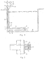
- the sludge robot of Figs. 1 and 2 may represent the construction which is adopted in the specimen contemplated herein.
- the sludge robot according to Fig. 1 has a round rising tube 3 attached to a tank wall 15 and connected to a motor coupling 1 by means of a socket 14. Rising tube 3 interconnects the socket 14 with a mammoth pump 10. To the underside of the motor coupling 1 an angle piece 4 is attached which is rigidly connected to a tube arm 5. In the outer end of the tube arm 5. there is provided an angle piece 6 which is rigidly connected therewith and secured to the upper side of the motor coupling 2.
- the motor coupling 2 is identical to the motor coupling 1.
- the motor couplings 1, 2, the tube arms 5, 8, rising tube 3 and the angle pieces 4, 6, 7, 9 have the same inside diameter.
- a cable 12 For current supply and control of the motor coupling 1 there is a cable 12 which is connected to a switch 13.
- a cable 11 is provided which preferably is connected to switch 13.
- This switch 13 is controlled by a micro dator 18 which is pre-programmed for the relevant tank size.
- Current supply is taken from the electrical network through a rectifier unit 17.
- the starting time for the sludge suction cycle is set by means of a timer 19, and the cycle time is adjusted by means of a control knob 20.
- Fig. 2 illustrates the motor coupling 1 and 2, respectively, whose construction consists of a stator 21 embedded in a plastic molding 23 in the exemplificatory embodiment described above.
- the plastic 23 constitutes a bearing casing for the coupling and is screwed to a plastic flange 24. Between the plastic flange 24 and the bearing casing 23 there is provided a second plastic flange 22 in which a rotor 25 is embedded by molding.
- the motor of the motor coupling is basically a reluctance reductor step motor having 5° rotation for each step.
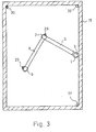
- FIG. 3 in which the same reference characters as above have been used for designating same or similar details, illustrates a further example of an electrical driving system.
- 15 is a plan view of a tank, the sludge robot being mounted on one longitudinal wall of the tank. Beneath the rising tube arm 3, the motor coupling 1 is connected to the tube arm 5, which has its other end connected to the motor coupling 2 as before. Furthermore, the tube arm 8 is connected between the motor coupling 2 and the suction angle 9.
- one supersonic transmitter 28 is mounted in connection with the motor coupling 2 and another supersonic transmitter 29 at the suction angle 9.
- the signals from the transmitters 28 and 29, respectively are picked up, and a micro dator calculates the position of the respective transmitters 28 and 29.
- a further transmitter 30 which constitutes a reference transmitter is mounted in one of the corners of the tank. By means of this reference transmitter 30 the measures of the tank 15 are also determined.
- a sludge robot which is driven pneumatically or hydraulically.
- the tube arms may also be more than two in number.
- the transmitters 28-30 and the appurtenant receivers may be constructed for other waves other than supersonic waves.
Landscapes
- Chemical & Material Sciences (AREA)
- Chemical Kinetics & Catalysis (AREA)
- Engineering & Computer Science (AREA)
- Power Engineering (AREA)
- Cleaning In General (AREA)
- Manipulator (AREA)
- Toys (AREA)
- Vehicle Interior And Exterior Ornaments, Soundproofing, And Insulation (AREA)
Applications Claiming Priority (2)
| Application Number | Priority Date | Filing Date | Title |
|---|---|---|---|
| SE7909592 | 1979-11-20 | ||
| SE7909592A SE427327B (sv) | 1979-11-20 | 1979-11-20 | Slamrobot |
Publications (2)
| Publication Number | Publication Date |
|---|---|
| EP0040203A1 EP0040203A1 (en) | 1981-11-25 |
| EP0040203B1 true EP0040203B1 (en) | 1983-03-23 |
Family
ID=20339356
Family Applications (1)
| Application Number | Title | Priority Date | Filing Date |
|---|---|---|---|
| EP80901980A Expired EP0040203B1 (en) | 1979-11-20 | 1980-10-28 | Sludge robot |
Country Status (8)
| Country | Link |
|---|---|
| US (1) | US4381237A (da) |
| EP (1) | EP0040203B1 (da) |
| DE (1) | DE3062460D1 (da) |
| DK (1) | DK152014C (da) |
| FI (1) | FI68976C (da) |
| NO (1) | NO149916C (da) |
| SE (1) | SE427327B (da) |
| WO (1) | WO1981001372A1 (da) |
Families Citing this family (4)
| Publication number | Priority date | Publication date | Assignee | Title |
|---|---|---|---|---|
| SE459742B (sv) * | 1985-01-31 | 1989-07-31 | Industrikonstruktioner Ab | Saett foer reglering av slamkoncentrationen hos slam, som uppsuges medelst aatminstone en inom en vattensamling roerlig, foersta sugenhet efter en uppgjord plan foer slammets omhaendertagande, vilket kraever ett foerutbestaemt minsta vatteninnehaall |
| US5534141A (en) * | 1994-12-09 | 1996-07-09 | The Lemna Corporation | Wastewater treatment system with in-pond clarifier |
| GB2332030B (en) * | 1997-12-05 | 2002-10-02 | Peter Ignatius Swan | Telescopic hose and related desludge drive systems |
| CN110694312B (zh) * | 2019-09-27 | 2021-08-27 | 合肥思筹科技有限公司 | 水下行走式污水处理沉降池刮泥机 |
Family Cites Families (11)
| Publication number | Priority date | Publication date | Assignee | Title |
|---|---|---|---|---|
| SE92843C1 (da) * | ||||
| NL16124C (da) * | 1923-02-15 | |||
| US2988762A (en) * | 1960-02-08 | 1961-06-20 | Hugh H Babcock | Self-steering submarine suction cleaner |
| FI43416B (da) * | 1964-07-23 | 1970-11-30 | Stenberg Flyght Ab | |
| US3416176A (en) * | 1967-08-09 | 1968-12-17 | Richards Of Rockford Inc | Unit for removing solids from tanks, reservoirs and the like |
| US3545618A (en) * | 1969-02-24 | 1970-12-08 | Koppers Co Inc | Apparatus to reclaim coke breeze from a quenching station sump |
| US3796658A (en) * | 1971-11-26 | 1974-03-12 | Bauer Eng Inc | Sludge reclamation system and method |
| SU667507A1 (ru) * | 1976-04-13 | 1979-06-15 | Всесоюзное научно-производственное объединение целлюлозно-бумажной промышленности | Установка дл удалени осадка из осадочных бассейнов |
| FR2352640A1 (fr) * | 1976-05-24 | 1977-12-23 | Bretagne Atel Chantiers | Telemanipulateur a faible encombrement |
| SE401099B (sv) * | 1976-11-18 | 1978-04-24 | Eie Maskin Ab N A | Slamsugareaggregat for sedimenteringsbassenger |
| EP0137050A1 (de) * | 1977-08-31 | 1985-04-17 | Grisebach, Hans-Theodor | Stellgerät mit Kugelschraubengetriebe |
-
1979
- 1979-11-20 SE SE7909592A patent/SE427327B/sv not_active IP Right Cessation
-
1980
- 1980-10-28 DE DE8080901980T patent/DE3062460D1/de not_active Expired
- 1980-10-28 WO PCT/SE1980/000260 patent/WO1981001372A1/en not_active Ceased
- 1980-10-28 EP EP80901980A patent/EP0040203B1/en not_active Expired
- 1980-10-28 US US06/285,107 patent/US4381237A/en not_active Expired - Fee Related
-
1981
- 1981-07-06 FI FI812113A patent/FI68976C/fi not_active IP Right Cessation
- 1981-07-13 DK DK309981A patent/DK152014C/da not_active IP Right Cessation
- 1981-07-16 NO NO812444A patent/NO149916C/no unknown
Also Published As
| Publication number | Publication date |
|---|---|
| FI812113L (fi) | 1981-07-06 |
| FI68976B (fi) | 1985-08-30 |
| DE3062460D1 (en) | 1983-04-28 |
| US4381237A (en) | 1983-04-26 |
| FI68976C (fi) | 1985-12-10 |
| NO149916B (no) | 1984-04-09 |
| DK152014B (da) | 1988-01-25 |
| WO1981001372A1 (en) | 1981-05-28 |
| NO149916C (no) | 1984-07-18 |
| EP0040203A1 (en) | 1981-11-25 |
| SE427327B (sv) | 1983-03-28 |
| DK309981A (da) | 1981-07-13 |
| DK152014C (da) | 1988-07-11 |
| NO812444L (no) | 1981-07-16 |
| SE7909592L (sv) | 1981-05-21 |
Similar Documents
| Publication | Publication Date | Title |
|---|---|---|
| US3665942A (en) | Swimming pool cleaning device | |
| RU2417815C2 (ru) | Устройство для сбора и/или удаления осадка | |
| EP0040203B1 (en) | Sludge robot | |
| KR101751424B1 (ko) | 진공 흡입식 해양생물 포집장치 | |
| CN109235402A (zh) | 一种洁水机器人以及智能洁水系统 | |
| US5234580A (en) | Decanting apparatus with float supported submerged pump | |
| FI64516C (fi) | Slamsugareaggregat foer sedimenteringsbassaenger | |
| US3496901A (en) | Floating pump with aerator | |
| US5200066A (en) | Oil spill collecting device with vortex generator | |
| CN112878407A (zh) | 一种快速清淤装置 | |
| CN222153062U (zh) | 一种高频加热设备的自动送料机构 | |
| US20090001030A1 (en) | Method and Apparatus for Collecting and/or Separating Solids from Liquids | |
| CN220696220U (zh) | 一种住宅室内施工用除尘装置 | |
| CN111544925B (zh) | 水面浮油清理装置 | |
| WO1993008919A1 (en) | Magnetic disc separator | |
| CN119195259B (zh) | 河道清淤设备及方法 | |
| CN107711682B (zh) | 一种索道牵引吸污装置 | |
| JPH1190425A (ja) | 液体回収装置 | |
| CA2129048C (en) | Decanting apparatus with float supported submerged pump | |
| CN222999305U (zh) | 一种输水管路堵塞清理设备 | |
| CN106400762B (zh) | 转刷式收油机 | |
| CN216665036U (zh) | 一种建筑水泥砂浆运输装置 | |
| JPS5925464Y2 (ja) | 流体撹拌装置 | |
| FR2442982A1 (fr) | Pompe centrifuge rotative | |
| SU1118422A2 (ru) | Устройство дл сбора краски |
Legal Events
| Date | Code | Title | Description |
|---|---|---|---|
| PUAI | Public reference made under article 153(3) epc to a published international application that has entered the european phase |
Free format text: ORIGINAL CODE: 0009012 |
|
| 17P | Request for examination filed |
Effective date: 19810630 |
|
| AK | Designated contracting states |
Designated state(s): DE GB |
|
| GRAA | (expected) grant |
Free format text: ORIGINAL CODE: 0009210 |
|
| AK | Designated contracting states |
Designated state(s): DE GB |
|
| REF | Corresponds to: |
Ref document number: 3062460 Country of ref document: DE Date of ref document: 19830428 |
|
| PLBI | Opposition filed |
Free format text: ORIGINAL CODE: 0009260 |
|
| 26 | Opposition filed |
Opponent name: PASSAVANT-WERKE AG & CO. KG Effective date: 19831223 |
|
| PLBN | Opposition rejected |
Free format text: ORIGINAL CODE: 0009273 |
|
| STAA | Information on the status of an ep patent application or granted ep patent |
Free format text: STATUS: OPPOSITION REJECTED |
|
| 27O | Opposition rejected |
Effective date: 19841116 |
|
| PGFP | Annual fee paid to national office [announced via postgrant information from national office to epo] |
Ref country code: GB Payment date: 19911022 Year of fee payment: 12 |
|
| PGFP | Annual fee paid to national office [announced via postgrant information from national office to epo] |
Ref country code: DE Payment date: 19911210 Year of fee payment: 12 |
|
| PG25 | Lapsed in a contracting state [announced via postgrant information from national office to epo] |
Ref country code: GB Effective date: 19921028 |
|
| GBPC | Gb: european patent ceased through non-payment of renewal fee |
Effective date: 19921028 |
|
| PG25 | Lapsed in a contracting state [announced via postgrant information from national office to epo] |
Ref country code: DE Effective date: 19930701 |