EP0040130B1 - Interrupteur électrique à poussoir vertical - Google Patents
Interrupteur électrique à poussoir vertical Download PDFInfo
- Publication number
- EP0040130B1 EP0040130B1 EP81400679A EP81400679A EP0040130B1 EP 0040130 B1 EP0040130 B1 EP 0040130B1 EP 81400679 A EP81400679 A EP 81400679A EP 81400679 A EP81400679 A EP 81400679A EP 0040130 B1 EP0040130 B1 EP 0040130B1
- Authority
- EP
- European Patent Office
- Prior art keywords
- switch
- button
- push
- rigidly connected
- mobile terminals
- Prior art date
- Legal status (The legal status is an assumption and is not a legal conclusion. Google has not performed a legal analysis and makes no representation as to the accuracy of the status listed.)
- Expired
Links
Images

Classifications
-
- H—ELECTRICITY
- H01—ELECTRIC ELEMENTS
- H01H—ELECTRIC SWITCHES; RELAYS; SELECTORS; EMERGENCY PROTECTIVE DEVICES
- H01H13/00—Switches having rectilinearly-movable operating part or parts adapted for pushing or pulling in one direction only, e.g. push-button switch
- H01H13/50—Switches having rectilinearly-movable operating part or parts adapted for pushing or pulling in one direction only, e.g. push-button switch having a single operating member
- H01H13/56—Switches having rectilinearly-movable operating part or parts adapted for pushing or pulling in one direction only, e.g. push-button switch having a single operating member the contact returning to its original state upon the next application of operating force
- H01H13/562—Switches having rectilinearly-movable operating part or parts adapted for pushing or pulling in one direction only, e.g. push-button switch having a single operating member the contact returning to its original state upon the next application of operating force making use of a heart shaped cam
- H01H13/568—Switches having rectilinearly-movable operating part or parts adapted for pushing or pulling in one direction only, e.g. push-button switch having a single operating member the contact returning to its original state upon the next application of operating force making use of a heart shaped cam the contact also returning by some external action, e.g. interlocking, protection, remote control
-
- Y—GENERAL TAGGING OF NEW TECHNOLOGICAL DEVELOPMENTS; GENERAL TAGGING OF CROSS-SECTIONAL TECHNOLOGIES SPANNING OVER SEVERAL SECTIONS OF THE IPC; TECHNICAL SUBJECTS COVERED BY FORMER USPC CROSS-REFERENCE ART COLLECTIONS [XRACs] AND DIGESTS
- Y10—TECHNICAL SUBJECTS COVERED BY FORMER USPC
- Y10S—TECHNICAL SUBJECTS COVERED BY FORMER USPC CROSS-REFERENCE ART COLLECTIONS [XRACs] AND DIGESTS
- Y10S200/00—Electricity: circuit makers and breakers
- Y10S200/42—Contact welding considerations
Definitions
- the present invention relates to an electrical switch with vertical pushbutton of a simple embodiment and yet of great safety, this switch being able to be easily fixed on control panels of various machines and being able to simultaneously control one or two electrical circuits.
- an electric push switch constituted by a main hollow body in which is slidable a push button one of whose lower parts supports two lugs maintaining pallets mobile carrying studs cooperating with studs integral with a bracket fixed to the bottom of the main body.
- the tab laterally carries a hollow and heart-shaped cam in which a lug can circulate constituting the upper part of a locking element.
- a spring centered on at least one finger secured to the underside of the push button is supported on the pallet.
- the switch of the invention allows successive switching on and off operations that are entirely gentle, since the friction forces are very low and the members constituting the electric switch are very reliable, whatever the orientation or position of the switch, i.e. even if the switch is in a substantially horizontal position.
- the constitution of such a switch makes it possible to obtain excellent contact because the mobile terminals come first to rest obliquely on the contact pads, then in parallel with a slight rolling movement so as to allow self-cleaning of the contact pads when closing or opening the switch.
- the vertical push-button electric switch is constituted by a hollowed-out main body in which the push-button can slide from top to bottom and from bottom to top, the lower part of which supports two tabs holding the pallets carrying terminals mobiles cooperating with studs integral with brackets fixed to the bottom of the main body; in addition, the tab laterally carries a hollow cam, generally in the shape of a heart, in which a lug can circulate fixed to the upper part of a pendulum articulated on an axis placed at the center of gravity of the balance, this axis being integral with the inner wall of the body so as to allow the opening and closing of at least one electrical circuit by the switch, this switch being characterized in that the pallet carrying the mobile terminals is held on hooks with upper inclined edges integral legs of the push button by a spring centered on at least one finger secured to the underside of the push button.
- the main body 1 of the switch which is constituted by a substantially cubic box 2 extended, at its central lower part, by a receptacle 3 narrow and elongated.
- the upper edge 2a of the box 2 ends in a frame 4 intended to come to rest on the outer surface of the control unit in which the switch is incorporated which is held there by elastic tabs 5, at the upper ends of which are provided ridged surfaces 5a.
- This switch fixing device is also known per se.
- the push button designated by 6, consists of a solid body extended downwards by tabs 7, 8.
- the latter carry hooks 9 intended to hold pallets 10 (see fig. 9) at the bottom of which mobile terminals are fixed intended to cooperate with fixed studs 12 mounted on conductive brackets 13 passing through the bottom of the box 2 (see fig. 2).
- the extra thickness 14, provided in the pallets 10, allows the centering of a spring 15 held by a finger 16 secured to the underside of the push button 6 (see fig. 2).
- the spring 15 thus firmly holds the pallets 10 on the oblique hooks 9 which can be inclined inward (see fig. 1 and 2) or outward (see fig. 5 and 6).
- a locking balance 20 is articulated on an axis 21 secured to one of the transverse sides of the box 2.
- This locking balance 20 has two parts, one long 20a and the other short 20b, the part 20a being provided at its upper end with a lug 22 located below the pivot axis 21.
- the two parts 20a and 20b of the locking balance 20 are calculated so that their center of gravity resulting passes through the pivot axis 21.
- a locking ball commonly used requires grease which hardens over time. It is also possible to use plastic locking washers which must be curved, which is all the more complicated as the curvature disappears with the increase in temperature, especially when the switch is used on devices or machines requiring, for their operation, heat.
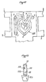
- the lug 21 is intended to cooperate with a cam 23 having substantially the shape of a heart hollowed out in the tab 7 of the push button 6, so that by pushing the push button 6 in the direction of the arrow F, (see fig. 4), the lug 22 which is located in the lower part of the hollow cam 23 (see fig. 10) follows a movement defined by the arrows F, o (see fig. 4) thereby allowing the closing of the electrical circuits controlled by the switch by application of the mobile terminals 11 on the fixed pads 12.
- a spring 30 placed behind the balance 20 tends to push up the push button 6 while resting on the bottom of the receptacle 3 and against a vertical guide 31 secured to the tab 7. The result is thus easy return to the switch open position when the lug 22 has left the central part 23a of the heart-shaped cam 23.
- the locking balance 120 is constituted by a bar passing through the bottom of the receptacle 3 so as to allow the control of this balance 120, from point 121, either by a linkage or by an electromagnet, thus allowing the switch remote control.
- the various parts constituting the switch are most often made of natural or synthetic plastic material, the dielectric nature of which no longer needs to be demonstrated and the resistance of which is extremely good. Only the brackets 13, the pallets 10, the terminals and studs 11, 12 as well as the springs are made of metal.
- the heart-shaped cam 23 may have in its central zone 123 (see FIG. 4) a dish leading to an inclined part allowing automatic and remote-controlled operation of the switch.
- the pendulum 220 can have a slight modification of its axis of rotation 223 which can be square. In any case, these modifications mean that the balance is perfectly balanced and can therefore constantly take up any position.
- the pin 22 takes position C (position engaged, circuit closed); if the pusher is pressed again, the stud 22 escapes towards position D; then, by releasing the pressure on the pusher, the pin 22 returns to position A (switch open, circuit open).
- the pin 22 is brought from position A to position B and the assembly is pivoted to the left towards position E, then the pressure on the pusher is released, a device with momentary action, the stud 22 circulating from position E to position F and from position F to position E.
Landscapes
- Push-Button Switches (AREA)
Applications Claiming Priority (2)
| Application Number | Priority Date | Filing Date | Title |
|---|---|---|---|
| FR8010364 | 1980-05-09 | ||
| FR8010364A FR2482363A1 (fr) | 1980-05-09 | 1980-05-09 | Interrupteur electrique a poussoir vertical |
Publications (2)
| Publication Number | Publication Date |
|---|---|
| EP0040130A1 EP0040130A1 (fr) | 1981-11-18 |
| EP0040130B1 true EP0040130B1 (fr) | 1983-11-02 |
Family
ID=9241801
Family Applications (1)
| Application Number | Title | Priority Date | Filing Date |
|---|---|---|---|
| EP81400679A Expired EP0040130B1 (fr) | 1980-05-09 | 1981-04-29 | Interrupteur électrique à poussoir vertical |
Country Status (4)
| Country | Link |
|---|---|
| US (1) | US4368368A (enExample) |
| EP (1) | EP0040130B1 (enExample) |
| DE (1) | DE3161313D1 (enExample) |
| FR (1) | FR2482363A1 (enExample) |
Families Citing this family (13)
| Publication number | Priority date | Publication date | Assignee | Title |
|---|---|---|---|---|
| KR890005142Y1 (ko) * | 1982-12-03 | 1989-08-02 | 알프스덴기 가부시기 가이샤 | 로크식 푸시 버튼 스위치 |
| DE3331987A1 (de) * | 1982-12-03 | 1984-01-26 | Alps Electric Co., Ltd., Tokyo | Druckknopf mit raststift und herzfoermiger rastnut |
| USD282067S (en) | 1982-12-24 | 1986-01-07 | Nippon Tsushin Kogyo Kabushiki Kaisha | Push button |
| CH675792A5 (enExample) * | 1988-02-04 | 1990-10-31 | Olten Ag Elektro Apparatebau | |
| FR2718566B1 (fr) * | 1994-04-08 | 1996-06-14 | Legrand Sa | Appareil électrique à poussoir. |
| DE19960695A1 (de) * | 1999-12-16 | 2001-06-21 | Moeller Gmbh | Drucktaste für Rast- und Tastfunktion |
| US6987233B2 (en) * | 2001-03-12 | 2006-01-17 | Magtech Usa, Inc. | Push-button type electrical switch having secondary conductive pathway to ground |
| US20040118669A1 (en) * | 2001-03-12 | 2004-06-24 | Mou Oliver C. | Gaming machine illuminated push-button switch |
| US6870114B2 (en) * | 2001-03-12 | 2005-03-22 | Joseph W. Cole | Method and apparatus for removing and replacing bulb of push-button type electrical switch |
| US6590176B2 (en) * | 2001-03-12 | 2003-07-08 | Joseph W. Cole | Push-button type electrical switch |
| DE10117345B4 (de) * | 2001-04-06 | 2008-05-15 | Siemens Ag | Elektrisches Schaltgerät, umstellbar von Tast- auf Schaltbetrieb |
| KR101570193B1 (ko) * | 2015-03-16 | 2015-11-18 | 주식회사 마이크로필터 | 반복밀어줌에 의하여 승강되는 승강체의 정방향의 상승을 유도하는 락킹-언락킹구조체 |
| DE102019107222A1 (de) * | 2019-03-21 | 2020-09-24 | Johnson Electric Germany GmbH & Co. KG | Elektrischer Drucktastenschalter |
Family Cites Families (6)
| Publication number | Priority date | Publication date | Assignee | Title |
|---|---|---|---|---|
| US2811617A (en) * | 1955-09-19 | 1957-10-29 | Gen Electric | Electric switch |
| NL229989A (enExample) * | 1957-07-29 | |||
| US3272949A (en) * | 1964-08-14 | 1966-09-13 | Allen Bradley Co | Bifurcated parallel contacts for relay |
| DE1765562B1 (de) * | 1968-02-21 | 1972-01-20 | Rudolf Schadow | Tastschalter |
| FR2133125A5 (enExample) * | 1971-04-08 | 1972-11-24 | Alexander Percy | |
| DE2411463A1 (de) * | 1974-03-11 | 1975-09-25 | Baer Elektrowerke Kg | Elektrischer installationsschalter |
-
1980
- 1980-05-09 FR FR8010364A patent/FR2482363A1/fr active Granted
-
1981
- 1981-04-29 DE DE8181400679T patent/DE3161313D1/de not_active Expired
- 1981-04-29 EP EP81400679A patent/EP0040130B1/fr not_active Expired
- 1981-05-08 US US06/261,980 patent/US4368368A/en not_active Expired - Fee Related
Also Published As
| Publication number | Publication date |
|---|---|
| EP0040130A1 (fr) | 1981-11-18 |
| DE3161313D1 (en) | 1983-12-08 |
| FR2482363B1 (enExample) | 1983-06-17 |
| US4368368A (en) | 1983-01-11 |
| FR2482363A1 (fr) | 1981-11-13 |
Similar Documents
| Publication | Publication Date | Title |
|---|---|---|
| EP0040130B1 (fr) | Interrupteur électrique à poussoir vertical | |
| EP0086908B1 (fr) | Chaussure de ski | |
| EP0167429A1 (fr) | Interrupteur multidirectionnel à commande par une bille | |
| FR2609161A1 (fr) | Appareil electromenager combinant grille-pain et four | |
| FR2673485A1 (fr) | Tige de raccordement de disjoncteurs pour montage automatique. | |
| FR2489585A1 (fr) | Commutateur a curseur a action brusque | |
| FR2796755A1 (fr) | Commutateur electrique a organe unique d'actionnement rotatif et axial | |
| WO2005099533A1 (fr) | Appareil electrique de chauffage de liquide | |
| FR2494893A1 (fr) | Interrupteur miniaturise a bouton | |
| EP0260171B1 (fr) | Appareil électrique muni d'une manette de commande manuelle avec indication des positions "marche" et "arrêt" | |
| FR2733085A1 (fr) | Commutateur electrique comportant un organe commun d'actionnement de deux contacts electriques mobiles | |
| EP0354101A1 (fr) | Dispositif pour verrouiller dans l'un quelconque des crans d'une crémaillère un doigt de réglage et fauteuil faisant application de ce dispositif | |
| EP0671673B1 (fr) | Bouton-poussoir contacteur | |
| FR2540419A1 (fr) | Couteau pliant a dispositif de verrouillage de lame, notamment pour activites de plein air | |
| FR2616265A1 (fr) | Interrupteur a accrochage | |
| FR2648615A1 (fr) | Perfectionnements aux interrupteurs a coupure automatique, notamment aux disjoncteurs et disjoncteurs differentiels | |
| BE1012503A3 (fr) | Dispositif pour un commutateur a bouton-poussoir, qui peut etre eclaire electriquement. | |
| CH629093A5 (fr) | Support pour un appareil electromenager, notamment un batteur. | |
| FR2793067A1 (fr) | Commutateur electrique multiple a organe d'actionnement unique | |
| EP0458711B1 (fr) | Disjoncteur à commande manuelle | |
| FR2601188A1 (fr) | Interrupteur electrique a bascule, transformable en interrupteur a touche | |
| EP0147293A1 (fr) | Dispositif de commutation électrique | |
| EP2442337B1 (fr) | Dispositif de contacteur clé | |
| FR2808467A1 (fr) | Appareil electrique de traitement d'aliments comportant un organe presseur | |
| FR2484820A1 (fr) | Manche amovible pour la prehension de plats, casseroles et objets analogues |
Legal Events
| Date | Code | Title | Description |
|---|---|---|---|
| PUAI | Public reference made under article 153(3) epc to a published international application that has entered the european phase |
Free format text: ORIGINAL CODE: 0009012 |
|
| 17P | Request for examination filed |
Effective date: 19810504 |
|
| AK | Designated contracting states |
Designated state(s): CH DE GB IT LI |
|
| ITCL | It: translation for ep claims filed |
Representative=s name: STUDIO ING. ALFREDO RAIMONDI |
|
| RAP1 | Party data changed (applicant data changed or rights of an application transferred) |
Owner name: PHOEBE S.A. |
|
| ITF | It: translation for a ep patent filed | ||
| GRAA | (expected) grant |
Free format text: ORIGINAL CODE: 0009210 |
|
| AK | Designated contracting states |
Designated state(s): CH DE GB IT LI |
|
| REF | Corresponds to: |
Ref document number: 3161313 Country of ref document: DE Date of ref document: 19831208 |
|
| PLBE | No opposition filed within time limit |
Free format text: ORIGINAL CODE: 0009261 |
|
| STAA | Information on the status of an ep patent application or granted ep patent |
Free format text: STATUS: NO OPPOSITION FILED WITHIN TIME LIMIT |
|
| 26N | No opposition filed | ||
| PGFP | Annual fee paid to national office [announced via postgrant information from national office to epo] |
Ref country code: GB Payment date: 19910205 Year of fee payment: 11 |
|
| PGFP | Annual fee paid to national office [announced via postgrant information from national office to epo] |
Ref country code: CH Payment date: 19910215 Year of fee payment: 11 |
|
| ITTA | It: last paid annual fee | ||
| PGFP | Annual fee paid to national office [announced via postgrant information from national office to epo] |
Ref country code: DE Payment date: 19910508 Year of fee payment: 11 |
|
| PG25 | Lapsed in a contracting state [announced via postgrant information from national office to epo] |
Ref country code: GB Effective date: 19920429 |
|
| PG25 | Lapsed in a contracting state [announced via postgrant information from national office to epo] |
Ref country code: LI Effective date: 19920430 Ref country code: CH Effective date: 19920430 |
|
| GBPC | Gb: european patent ceased through non-payment of renewal fee | ||
| REG | Reference to a national code |
Ref country code: CH Ref legal event code: PL |
|
| PG25 | Lapsed in a contracting state [announced via postgrant information from national office to epo] |
Ref country code: DE Effective date: 19930101 |