EP0040115B1 - Procédé pour fabriquer un stator de machine dynamo-électrique, ébauche s'y rapportant, et stator obtenu par ce procédé - Google Patents
Procédé pour fabriquer un stator de machine dynamo-électrique, ébauche s'y rapportant, et stator obtenu par ce procédé Download PDFInfo
- Publication number
- EP0040115B1 EP0040115B1 EP81400601A EP81400601A EP0040115B1 EP 0040115 B1 EP0040115 B1 EP 0040115B1 EP 81400601 A EP81400601 A EP 81400601A EP 81400601 A EP81400601 A EP 81400601A EP 0040115 B1 EP0040115 B1 EP 0040115B1
- Authority
- EP
- European Patent Office
- Prior art keywords
- stator
- tongues
- wire
- windings
- winding frame
- Prior art date
- Legal status (The legal status is an assumption and is not a legal conclusion. Google has not performed a legal analysis and makes no representation as to the accuracy of the status listed.)
- Expired
Links
- 238000000034 method Methods 0.000 title claims description 9
- 238000004519 manufacturing process Methods 0.000 title claims description 8
- 238000004804 winding Methods 0.000 claims description 36
- 210000002105 tongue Anatomy 0.000 claims description 19
- 238000005192 partition Methods 0.000 claims description 8
- 239000006223 plastic coating Substances 0.000 description 3
- 238000009434 installation Methods 0.000 description 2
- 238000005452 bending Methods 0.000 description 1
- 230000007423 decrease Effects 0.000 description 1
- 230000006866 deterioration Effects 0.000 description 1
- 239000000463 material Substances 0.000 description 1
- 238000000465 moulding Methods 0.000 description 1
- 230000000717 retained effect Effects 0.000 description 1
- 125000006850 spacer group Chemical group 0.000 description 1
Images

Classifications
-
- H—ELECTRICITY
- H02—GENERATION; CONVERSION OR DISTRIBUTION OF ELECTRIC POWER
- H02K—DYNAMO-ELECTRIC MACHINES
- H02K15/00—Processes or apparatus specially adapted for manufacturing, assembling, maintaining or repairing of dynamo-electric machines
- H02K15/08—Forming windings by laying conductors into or around core parts
- H02K15/095—Forming windings by laying conductors into or around core parts by laying conductors around salient poles
Definitions
- the present invention relates to a method of manufacturing a dynamo-electric machine stator, in particular a small electric motor with a closed magnetic circuit, of the type commonly called a universal motor.
- the invention also relates to a stator blank for applying this method, and a stator obtained by this method.
- the stators referred to here generally have a certain number of pole shoes directed towards the inside of the ring forming the magnetic circuit.
- a stator winding held captive in the notches thus formed between the ring and the opening.
- the winding is generally isolated from the stator using insulating paper.
- the winding is remote from the rotor and retained towards the outside by various means such as, in particular, a tongue which extends the pole shoe axially.
- Such windings can easily be wound mechanically using a T-needle inserted along the axis of the machine and driven by an alternating rotary movement combined with an axial translation movement.
- the present invention aims to achieve a manufacturing process which overcomes this subjection.
- this blank includes a magnetic core at least partially insulated by a plastic coating and having a number of polar expansions which provide notches for retaining stator windings in cooperation with retaining tabs which extend these expansions axially. It is characterized in that the tongues are extended axially on the blank by profiled means forming an integral part with them for guiding the wire of the windings during the winding of the latter, these guide means being connected to said tongues by thinned zones constituting zones of preferential rupture.
- said means for guiding the wire of the windings comprise guide projections tapered towards the outside of the stator.
- the needle deposits the thread towards the point of the projection, then the thread slides along the generally conical surface of the projection to be aminated in the layer.
- said guide projections are hollowed out and each comprise several partitions converging towards the outside and the edges of which constitute approximately generators of an ideal cone enveloping the projection.
- This embodiment requiring little material, is particularly economical.
- the retaining tabs have, in the vicinity of their junction with the guide projections, edges extending radially to help retain the windings, if they tended to project beyond the end tabs.
- edges of the tongues are situated substantially in planes perpendicular to the axis of rotation of the machine.
- edges can thus serve as a stable support for the stator after removal of the guide projections, allowing it to be placed, with the vertical axis, on a work or storage surface without any risk of deterioration of the windings.
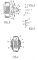
- the stator blank comprises an annular magnetic core 1 with a laminated structure overmolded in a plastic coating 2.
- This core has two polar expansions 3 which provide notches for receiving stator windings 4 (FIG. 6) .
- Retaining tabs 5 extend axially the openings 3 and help to retain the windings 4.
- Tapered projections 6 themselves axially extend the tongues 5 and form a one-piece assembly with the stator, obtained during the aforementioned overmolding.
- Each projection consists of a central partition 7 and two lateral partitions 8 which converge towards the outside of the stator and whose height decreases progressively towards the outside.
- the projections 6 constitute outwardly tapered members, the tops of the partitions being inscribed substantially in a half-cone.
- the three partitions are substantially rehabilitated at the tapered end 9 of the projection 6, and they are also held together by spacers 11 in the vicinity of the base of the cone.
- the three partitions form a single piece with the corresponding tongue 5 by means of three thinned zones 12 which form a preferential breaking zone when an attempt is made to separate the projections from the assembly by bending and breaking.
- Borders 13 extend radially at the outer end of each tongue 5 to form, with said tongues and the annular core 1, a total of four U-shaped notches into which the windings 4 are inserted (FIG. 2). These edges are located just behind the thinned areas 12, so that they remain after removal of the projections 6 ( Figure 6). These edges have a perimeter which fits inside the cone circumscribed by the partitions 7, 8. They are located respectively in two planes perpendicular to the axis of the stator, so that they can serve as stable support for the stator on a plane once the projections 6 removed.
- a blank is produced as shown in Figures 1 to 5, that is to say comprising, coming from molding, the four projections 6 extending axially the two pole shoes.
- the windings are wound in a manner known per se by means of a T-shaped needle 14 (FIG. 1) driven by an alternating rotation movement, the alternations of which are separated by movements of axial translation.
- the needle passes the wire 15 behind the projection 6, and this wire slides along this projection to find itself in the U-shaped notch, behind the edges 13.
- the needle is moved axially until it exits on the other side of the rotor, then makes a U-turn in the other direction before being again moved axially to resume the position of FIG. 1 where it performs another half tower.
- edges 13 constitute perfectly stable supports for the rotor which, moreover, as shown in FIG. 7, effectively protect the windings.
- the invention is not limited to the example described, but covers any variant, in particular in the structure of the projections 6 which must only fulfill the condition of being generally tapered.
Landscapes
- Engineering & Computer Science (AREA)
- Manufacturing & Machinery (AREA)
- Power Engineering (AREA)
- Manufacture Of Motors, Generators (AREA)
Applications Claiming Priority (2)
| Application Number | Priority Date | Filing Date | Title |
|---|---|---|---|
| FR8010822 | 1980-05-14 | ||
| FR8010822A FR2484728A1 (fr) | 1980-05-14 | 1980-05-14 | Procede pour fabriquer un stator de machine-electrique, ebauche s'y rapportant, et stator obtenu par ce procede |
Publications (2)
| Publication Number | Publication Date |
|---|---|
| EP0040115A1 EP0040115A1 (fr) | 1981-11-18 |
| EP0040115B1 true EP0040115B1 (fr) | 1983-03-23 |
Family
ID=9241980
Family Applications (1)
| Application Number | Title | Priority Date | Filing Date |
|---|---|---|---|
| EP81400601A Expired EP0040115B1 (fr) | 1980-05-14 | 1981-04-15 | Procédé pour fabriquer un stator de machine dynamo-électrique, ébauche s'y rapportant, et stator obtenu par ce procédé |
Country Status (4)
| Country | Link |
|---|---|
| EP (1) | EP0040115B1 (enExample) |
| AU (1) | AU6962781A (enExample) |
| DE (1) | DE3160125D1 (enExample) |
| FR (1) | FR2484728A1 (enExample) |
Families Citing this family (5)
| Publication number | Priority date | Publication date | Assignee | Title |
|---|---|---|---|---|
| FR2569503B1 (fr) * | 1984-08-22 | 1988-07-22 | Etri Sa | Moteur electrique a element electromagnetique exterieur, procede pour le realiser, et habillage isolant et dispositif de guidage pour la mise en oeuvre du procede |
| IT8521630U1 (it) * | 1985-04-24 | 1986-10-24 | Axis Spa | Forme di avvolgimenti per statori di motori elettrici, realizzate di pezzo con la testata isolante |
| US4612702A (en) * | 1985-05-22 | 1986-09-23 | Black & Decker Inc. | Field coil winding |
| EP0387411B1 (en) * | 1989-03-13 | 1994-11-02 | AXIS S.p.A. | Methods and apparatus for producing stators with coil terminations at both ends |
| US6325318B1 (en) * | 1999-01-13 | 2001-12-04 | Axis Usa, Inc. | Wire guide for winding dynamo-electric machine stators without shrouds |
Citations (1)
| Publication number | Priority date | Publication date | Assignee | Title |
|---|---|---|---|---|
| FR2055099A5 (enExample) * | 1969-07-16 | 1971-05-07 | Rotel Ag |
Family Cites Families (1)
| Publication number | Priority date | Publication date | Assignee | Title |
|---|---|---|---|---|
| DE2849212C2 (de) * | 1978-11-13 | 1982-06-24 | Siemens AG, 1000 Berlin und 8000 München | Wickelwerkzeug für das Bewickeln der Ständerblechpakete von Universalmotoren |
-
1980
- 1980-05-14 FR FR8010822A patent/FR2484728A1/fr active Granted
-
1981
- 1981-04-15 DE DE8181400601T patent/DE3160125D1/de not_active Expired
- 1981-04-15 EP EP81400601A patent/EP0040115B1/fr not_active Expired
- 1981-04-16 AU AU69627/81A patent/AU6962781A/en not_active Abandoned
Patent Citations (1)
| Publication number | Priority date | Publication date | Assignee | Title |
|---|---|---|---|---|
| FR2055099A5 (enExample) * | 1969-07-16 | 1971-05-07 | Rotel Ag |
Also Published As
| Publication number | Publication date |
|---|---|
| DE3160125D1 (en) | 1983-04-28 |
| AU6962781A (en) | 1981-11-19 |
| EP0040115A1 (fr) | 1981-11-18 |
| FR2484728B1 (enExample) | 1982-07-02 |
| FR2484728A1 (fr) | 1981-12-18 |
Similar Documents
| Publication | Publication Date | Title |
|---|---|---|
| CN102457149B (zh) | 定子、无刷电动机以及它们的制造方法 | |
| EP2677633B1 (fr) | Isolant de bobine composé et élément de machine électrique associé | |
| EP3118978B1 (en) | Stator manufacturing device and manufacturing method | |
| KR101958890B1 (ko) | 전자적으로 정류되는 dc 모터 | |
| FR2793085A1 (fr) | Alternateur pour vehicule automobile a aimants interpolaires | |
| JP2744532B2 (ja) | 電動機の電機子および該電機子の巻き付け並びに製造方法 | |
| EP0040115B1 (fr) | Procédé pour fabriquer un stator de machine dynamo-électrique, ébauche s'y rapportant, et stator obtenu par ce procédé | |
| JP5453881B2 (ja) | モータ | |
| FR3067879B1 (fr) | Stator vrille et procede de fabrication | |
| US20240380271A1 (en) | Winding guide for a rotor of an electric motor | |
| JP5453880B2 (ja) | モータ | |
| JPH01286753A (ja) | 整流子 | |
| US2176361A (en) | Radial commutator | |
| EP3170246A1 (fr) | Procede de realisation d'un stator bobine de machine electrique tournante | |
| JPH04121641U (ja) | 電磁スイツチのソレノイドコイル用ボビン | |
| WO2018020168A1 (fr) | Machine électrique tournante munie d'un interconnecteur à traces de couplage empilées radialement | |
| FR3054748B1 (fr) | Machine electrique tournante munie d'un interconnecteur a traces de couplage empilees radialement | |
| JPH0524740B2 (enExample) | ||
| EP0157707A2 (fr) | Procédé pour fabriquer un bobinage d'un moteur synchrone à aimants permanents pour l'entraînement d'un gyroscope | |
| FR2569503A1 (fr) | Moteur electrique a element electromagnetique exterieur, procede pour le realiser, et habillage isolant et dispositif de guidage pour la mise en oeuvre du procede | |
| JP2005110342A (ja) | ステータの製造方法、コイル巻線装置、ステータの製造装置、ステータ、及びモータ | |
| EP3214734A1 (fr) | Stator de machine electrique tournante muni d'un bobinage à au moins un enroulement de phase masqué | |
| JP4468112B2 (ja) | 3相回転電機およびその製造方法 | |
| JP2024504191A (ja) | ブラシレスdcモータのためのステータを製造するための方法及び装置 | |
| WO2024189181A1 (fr) | Isolant de bobine destiné à être positionné autour d'une dent d'un stator ou d'un rotor d'une machine électrique |
Legal Events
| Date | Code | Title | Description |
|---|---|---|---|
| PUAI | Public reference made under article 153(3) epc to a published international application that has entered the european phase |
Free format text: ORIGINAL CODE: 0009012 |
|
| 17P | Request for examination filed |
Effective date: 19810418 |
|
| AK | Designated contracting states |
Designated state(s): CH DE GB IT NL |
|
| ITCL | It: translation for ep claims filed |
Representative=s name: BARZANO' E ZANARDO ROMA S.P.A. |
|
| DET | De: translation of patent claims | ||
| TCNL | Nl: translation of patent claims filed | ||
| ITF | It: translation for a ep patent filed | ||
| GRAA | (expected) grant |
Free format text: ORIGINAL CODE: 0009210 |
|
| AK | Designated contracting states |
Designated state(s): CH DE GB IT LI NL |
|
| REF | Corresponds to: |
Ref document number: 3160125 Country of ref document: DE Date of ref document: 19830428 |
|
| PGFP | Annual fee paid to national office [announced via postgrant information from national office to epo] |
Ref country code: NL Payment date: 19840430 Year of fee payment: 4 |
|
| PGFP | Annual fee paid to national office [announced via postgrant information from national office to epo] |
Ref country code: CH Payment date: 19840503 Year of fee payment: 4 |
|
| PGFP | Annual fee paid to national office [announced via postgrant information from national office to epo] |
Ref country code: DE Payment date: 19840620 Year of fee payment: 4 |
|
| PG25 | Lapsed in a contracting state [announced via postgrant information from national office to epo] |
Ref country code: NL Effective date: 19851101 |
|
| NLV4 | Nl: lapsed or anulled due to non-payment of the annual fee | ||
| PG25 | Lapsed in a contracting state [announced via postgrant information from national office to epo] |
Ref country code: DE Effective date: 19860101 |
|
| PG25 | Lapsed in a contracting state [announced via postgrant information from national office to epo] |
Ref country code: LI Effective date: 19860430 Ref country code: CH Effective date: 19860430 |
|
| GBPC | Gb: european patent ceased through non-payment of renewal fee | ||
| REG | Reference to a national code |
Ref country code: CH Ref legal event code: PL |
|
| PG25 | Lapsed in a contracting state [announced via postgrant information from national office to epo] |
Ref country code: GB Effective date: 19881118 |
|
| PLBE | No opposition filed within time limit |
Free format text: ORIGINAL CODE: 0009261 |
|
| STAA | Information on the status of an ep patent application or granted ep patent |
Free format text: STATUS: NO OPPOSITION FILED WITHIN TIME LIMIT |