EP0039514A2 - Appareil pour la fabrication de crèmes glacées - Google Patents
Appareil pour la fabrication de crèmes glacées Download PDFInfo
- Publication number
- EP0039514A2 EP0039514A2 EP81103399A EP81103399A EP0039514A2 EP 0039514 A2 EP0039514 A2 EP 0039514A2 EP 81103399 A EP81103399 A EP 81103399A EP 81103399 A EP81103399 A EP 81103399A EP 0039514 A2 EP0039514 A2 EP 0039514A2
- Authority
- EP
- European Patent Office
- Prior art keywords
- mold
- cups
- conveyor
- confection
- screws
- Prior art date
- Legal status (The legal status is an assumption and is not a legal conclusion. Google has not performed a legal analysis and makes no representation as to the accuracy of the status listed.)
- Withdrawn
Links
- 235000009508 confectionery Nutrition 0.000 title claims abstract description 138
- 239000000463 material Substances 0.000 claims abstract description 57
- 238000007710 freezing Methods 0.000 claims description 24
- 230000008014 freezing Effects 0.000 claims description 24
- 238000011144 upstream manufacturing Methods 0.000 claims description 22
- 239000000969 carrier Substances 0.000 claims description 14
- 238000001816 cooling Methods 0.000 claims description 2
- 238000000151 deposition Methods 0.000 claims 4
- 238000004140 cleaning Methods 0.000 abstract description 25
- 230000007306 turnover Effects 0.000 abstract description 22
- 239000000945 filler Substances 0.000 abstract description 21
- 239000012267 brine Substances 0.000 description 32
- 238000000605 extraction Methods 0.000 description 32
- HPALAKNZSZLMCH-UHFFFAOYSA-M sodium;chloride;hydrate Chemical compound O.[Na+].[Cl-] HPALAKNZSZLMCH-UHFFFAOYSA-M 0.000 description 32
- XLYOFNOQVPJJNP-UHFFFAOYSA-N water Substances O XLYOFNOQVPJJNP-UHFFFAOYSA-N 0.000 description 13
- 239000007921 spray Substances 0.000 description 6
- 238000010276 construction Methods 0.000 description 5
- QGZKDVFQNNGYKY-UHFFFAOYSA-N Ammonia Chemical compound N QGZKDVFQNNGYKY-UHFFFAOYSA-N 0.000 description 3
- 238000000926 separation method Methods 0.000 description 3
- 230000001133 acceleration Effects 0.000 description 2
- 235000015243 ice cream Nutrition 0.000 description 2
- 238000004519 manufacturing process Methods 0.000 description 2
- 238000000034 method Methods 0.000 description 2
- 239000002344 surface layer Substances 0.000 description 2
- 238000005406 washing Methods 0.000 description 2
- 229910021529 ammonia Inorganic materials 0.000 description 1
- 239000003638 chemical reducing agent Substances 0.000 description 1
- 238000011109 contamination Methods 0.000 description 1
- 230000005574 cross-species transmission Effects 0.000 description 1
- 230000001419 dependent effect Effects 0.000 description 1
- 238000010586 diagram Methods 0.000 description 1
- 230000009969 flowable effect Effects 0.000 description 1
- 239000012530 fluid Substances 0.000 description 1
- 238000010438 heat treatment Methods 0.000 description 1
- 238000009413 insulation Methods 0.000 description 1
- 239000012774 insulation material Substances 0.000 description 1
- 230000007257 malfunction Effects 0.000 description 1
- 239000002184 metal Substances 0.000 description 1
- 230000004048 modification Effects 0.000 description 1
- 238000012986 modification Methods 0.000 description 1
- 239000012768 molten material Substances 0.000 description 1
- 238000005057 refrigeration Methods 0.000 description 1
- 230000000284 resting effect Effects 0.000 description 1
- 238000005507 spraying Methods 0.000 description 1
- 229910001220 stainless steel Inorganic materials 0.000 description 1
- 239000010935 stainless steel Substances 0.000 description 1
Images


Classifications
-
- A—HUMAN NECESSITIES
- A23—FOODS OR FOODSTUFFS; TREATMENT THEREOF, NOT COVERED BY OTHER CLASSES
- A23G—COCOA; COCOA PRODUCTS, e.g. CHOCOLATE; SUBSTITUTES FOR COCOA OR COCOA PRODUCTS; CONFECTIONERY; CHEWING GUM; ICE-CREAM; PREPARATION THEREOF
- A23G9/00—Frozen sweets, e.g. ice confectionery, ice-cream; Mixtures therefor
- A23G9/04—Production of frozen sweets, e.g. ice-cream
- A23G9/14—Continuous production
- A23G9/16—Continuous production the products being within a cooled chamber, e.g. drum
- A23G9/163—Continuous production the products being within a cooled chamber, e.g. drum with intermittent operation
-
- A—HUMAN NECESSITIES
- A23—FOODS OR FOODSTUFFS; TREATMENT THEREOF, NOT COVERED BY OTHER CLASSES
- A23G—COCOA; COCOA PRODUCTS, e.g. CHOCOLATE; SUBSTITUTES FOR COCOA OR COCOA PRODUCTS; CONFECTIONERY; CHEWING GUM; ICE-CREAM; PREPARATION THEREOF
- A23G7/00—Other apparatus or process specially adapted for the chocolate or confectionery industry
- A23G7/0037—Apparatus for orientating and reorienting objects, e.g. chocolate, confectionery, trays, moulds, except sticks
-
- A—HUMAN NECESSITIES
- A23—FOODS OR FOODSTUFFS; TREATMENT THEREOF, NOT COVERED BY OTHER CLASSES
- A23G—COCOA; COCOA PRODUCTS, e.g. CHOCOLATE; SUBSTITUTES FOR COCOA OR COCOA PRODUCTS; CONFECTIONERY; CHEWING GUM; ICE-CREAM; PREPARATION THEREOF
- A23G9/00—Frozen sweets, e.g. ice confectionery, ice-cream; Mixtures therefor
- A23G9/04—Production of frozen sweets, e.g. ice-cream
- A23G9/22—Details, component parts or accessories of apparatus insofar as not peculiar to a single one of the preceding groups
- A23G9/228—Arrangement and mounting of control or safety devices
-
- A—HUMAN NECESSITIES
- A23—FOODS OR FOODSTUFFS; TREATMENT THEREOF, NOT COVERED BY OTHER CLASSES
- A23G—COCOA; COCOA PRODUCTS, e.g. CHOCOLATE; SUBSTITUTES FOR COCOA OR COCOA PRODUCTS; CONFECTIONERY; CHEWING GUM; ICE-CREAM; PREPARATION THEREOF
- A23G9/00—Frozen sweets, e.g. ice confectionery, ice-cream; Mixtures therefor
- A23G9/04—Production of frozen sweets, e.g. ice-cream
- A23G9/22—Details, component parts or accessories of apparatus insofar as not peculiar to a single one of the preceding groups
- A23G9/26—Details, component parts or accessories of apparatus insofar as not peculiar to a single one of the preceding groups for producing frozen sweets on sticks
Definitions
- the present invention relates to apparatus for producing frozen confections of the type usually made from ice cream or water ice, and more particularly, the present invention concerns an apparatus for making such frozen confections in which the frozen portion of the confection is in the form of a block from which a stick or handle projects.
- One type of apparatus for producing frozen stick confections includes a plurality of removable mold bars or strips and an endless chain conveyor for indexing the mold strips in closely spaced arrangement through a brine tank to freeze confection material that has been deposited in mold cups depending from and integrally formed in the mold strips. After the confection material is partially frozen, sticks are inserted therein to project upwardly from the mold strips. After the confection material is completely frozen, the mold strips are lifted out of the brine tank by the endless chain conveyor and are moved under an extractor. At the extractor station, the mold cups are heated to permit the frozen confections to be separated therefrom. The sticks projecting from the frozen confections are then grasped and pulled upwardly to simultaneously extract the frozen confections from a row of mold cups in a mold strip.
- Another type of prior art frozen confection producing machine includes a relatively massive, flat annular mold member that includes a plurality of rows of mold cups which extend radially of the mold member. It should be noted that the annular mold member may be comprised of annular sectors rather than being unitary.
- This type of frozen confection producing apparatus further includes an annular brine tank through which the mold cups are conveyed by rotating the mold member about its axis.
- a confection filler is disposed at one end of the brine tank to successively deposit confection material into a radially extending row of mold cups, and an extractor device is provided for removing frozen confections from the cups after the row has been rotated through the brine tank.
- a stick inserter is mounted .along the arcuate path between the filler and extractor.
- a major problem associated with the linear type of frozen confection producing apparatus is that a substantial portion of the rows of mold cups are not in active use. That is to say, there are rows of mold cups that are empty and thus out of active use during that part of their path of travel that extends between the extractor station and the filler station.
- approximately 60% of the mold strips are positioned between the extractor and filler stations and therefore 60% of the mold strips are out of active use (with most of such mold strips being contained in the lower reach of the conveyor that extends below the brine tank).
- Even in the rotary apparatus some rows of mold cups will be out of active use at any time since a portion of the circular path of travel of the mold cups occurs beneath the extraction device. Since the mold members are typically fabricated from stainless steel, the mold members comprise a major portion of the total cost of the confection producing apparatus, and thus any measure which would maximize the number of molds in active use will be seen to be desirable.
- a problem particularly associated with the rotary frozen confection producing apparatus is that an operator is usually provided to inspect the mold cups downstream of the extraction station and to manually remove any substantial amount of confection material that may be left in the mold cups, particularly whole . frozen confections. It will be understood that if the extractor fails to remove a frozen confection from a mold cup, then unless such missed confection or product is removed by the operator, the filler will deposit new confection material into such cup so that it overflows the cup. It is further noted that there is always a possibility that the stick inserter will fail to insert a stick; accordingly, the extractor will fail to remove the stickless confection due to such failure of the stick inserter. In view of such possibilities of extractor failure, an operator is routinely provided to oversee the operation of the rotary type of confection producing machine.
- the confection producing apparatus of the Rasmusson patent 3,031,978 eliminates the need for such an operator because all of the mold strips are automatically and invariably inverted and cleaned as they are returned from the extractor station to the filler station. Such -leaning is sufficient to remove any missed confection that is not extracted from a mold cup.
- an apparatus for freezing confections which substantially reduces the number of mold members that are out of active use.
- the freezing apparatus of the present invention includes a plurality of separate mold members, each mold member including at least one row of mold cups depending therefrom.
- the apparatus further includes a conveyor for moving the mold members in a rectangular pattern, first in a single file along a relatively long lane during which confection material is deposited into the mold cups and during which sticks may be inserted into the confection material.
- the filling lane the mold members are moved one at a time laterally to an extraction lane wherein the molds are moved in the opposite direction in a single file that is parallel to and closely spaced from the filling lane.
- the confections are completely frozen in such second lane, and prior to the end of such lane, an extractor-conveyor is positioned to remove the frozen confections from the mold cups. The extractor-conveyor then transfers the frozen confections to a wrapper apparatus. After such extraction, the empty mold member is moved laterally from the extraction lane back to the starting position or upstream end of the filling lane. With this rectangular conveyor arrangement, only one mold member is necessarily out of use between the extractor and the filler--the member that is being laterally transferred between the parallel filling and extraction lanes.
- a minimum lapse of time occurs as the empty mold member moves from the extraction station to the filler station, thereby minimizing the possibility of any hygiene problems associated with the minor amounts of the confection material which may be left in the mold cups after extraction of the frozen confections. Also, due to the compactness of the overall rectangular arrangement of the mold members, a minimum amount of floor space is required for the confection producing apparatus.
- the mold members are pivotally mounted upon cradles or carriers so they may be inverted thereon, and a mold cleaning system is provided between the extraction station and the filler station, preferably at the upstream end of the filling lane.
- a mold cleaning system is provided between the extraction station and the filler station, preferably at the upstream end of the filling lane.
- At the cleaning station either all mold members or only selected mold members are, as desired, inverted and cleaned.
- such mold cleaning system selectively cleans only those mold members that have been detected to have a substantial amount of confection material in any mold cup thereof.
- Such selective cleaning apparatus includes a detector for sensing whether a substantial amount of confection material (such as an entire missed confection product) is left in a mold cup of a mold member that is transferred from the extraction station and further includes a turnover device that is responsive to the detector for thereafter inverting such mold member.
- the cleaning apparatus further includes a device for spraying fluid, such as a high pressure air blast, into the mold cups to remove detected confection material from the inverted mold member.
- the cleaning system also includes a device for returning an inverted mold member to its original orientation with the mold cups facing upwardly before it arrives at the filler station.
- the preferred selective cleaning system is thus advantageously adapted to permit a mold member that contains only minor residual amounts of confection material in the cups to remain in its normal upright orientation without being inverted so that such residual confection material may be re-utilized; on the other hand, the preferred cleaning system is adapted to invert a mold member to remove any confection material which occupies a substantial portion of a mold cup in the mold, such as would be the case when either the stick inserter or extractor malfunctions.
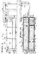
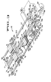
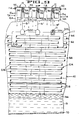
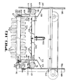
- an apparatus 10 for producing frozen confections C of the type including a bar or block of confection material having a stick S partially embedded therein (Fig. 6) is there shown and generally comprises a freezing apparatus 11 that includes a plurality of removable elongate mold strips 12 and a conveyor including several conveyor screws 76-86 (Fig. 3) for indexing the mold strips through a rectangular path of travel.
- the path of travel comprises relatively long, parallel, closely spaced filling and extraction lanes Ll and L2, respectively, and short lateral transfer legs extending between the ends of the filling and extraction lanes.
- confection material is deposited by a filler 14 into the cups or compartments 12a of the mold strips, and the confection material is partially frozen within the cups by means of cold brine being upwardly directed in jets from freezer nozzles 17 (Fig. 3) against the bottoms of the mold strips.
- Sticks are inserted into the confection material in the mold cups by an inserter 16 after the confection material has been partially frozen. It should be noted that the position of the stick inserter is dependent on the freezing rate of the confection material.
- the rectangular path of travel of the mold strips includes a lateral transfer leg extending between the downstream end of the filling lane Ll and the upstream end of the extracting lane L2 (Fig. 2).
- the extracting lane L2 comprises the third leg of the rectangular path of travel of the mold strips, and in this lane the confections are completely frozen by means of jets of brine that are upwardly directed against the mold strips from nozzles 17'. After being completely frozen, the frozen confections are separated from the mold strips by a pre-extractor 21 and an extractor assembly 18 of an extractor-conveyor 19 that is mounted over the downstream end of the extracting lane L2. The extracted frozen confections are then transferred by the extractor-conveyor to a wrapper 20 (shown in part).
- the final leg of the rectangular path of travel is the end transfer leg extending at a right angle between the downstream end of the extraction lane L2 and the upstream end of the filling lane Ll.
- the extractor assembly 18 is positioned closely adjacent the downstream end of the extraction lane (Fig. 2) so that only one mold strip is out of active use in such lane, i.e., the strip that is being transferred to the filling lane.
- the inserter 16 is disclosed in a copending United States patent application that was concurrently filed herewith by B. M. Harper et al, such application being entitled, Inserting Sticks Into Confections, and being identified by Attorney's Docket No. 8947;
- the extractor-conveyor 19 is disclosed in the United States patent application that was concurrently filed herewith by S. D. Cross et al, this application being entitled, Stick Confection Extraction Apparatus, and being identified by Attorney's Docket No. 8950. The disclosures of these.
- the filler 14 is constructed generally in accordance with the disclosure of U. S. patent 2,850,051 to M.' B. Rasmusson with, however, the filler spouts (not shown) thereof being adapted to the relatively reduced spacing between the mold cups 12a, as hereinafter described.
- the extractor-conveyor and stick inserter operate generally as described in the aforementioned U.S. patent 3,031,978 to Rasmusson.
- the stick inserter of the aforementioned Harper et al application is adapted to insert sticks at closer spacings and in different orientations relative to the direction of travel of the mold strips 12 and that the extractor-conveyor of the aforementioned Cross et al application accommodates the stick spacings and orientations.
- the pre-extractor 21 is positioned upstream of the extractor-conveyor 19 for loosening the frozen confections from the mold cups 12a to enable the extractor assembly 18 to readily remove the confections without further heating of the mold cups 12a.
- the pre-extractor includes a defrost spray system (not shown) for directing hot water against the undersides of the mold cups to enable the confections to be separated and an extractor assembly (not shown) that includes springloaded grippers for individually biasing the confections to extract the confections from the mold cups momentarily and then drop them back into the mold cups.
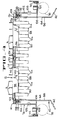
- the freezing apparatus 11 includes a mold cleaning system 22 that is located at the upstream end of the filling lane L l for selectively and automatically cleaning any relatively large amounts of confection material from the mold cups 12a, such as a whole frozen confection that may have been accidentally left in a cup after passing under the extractor 18 (such missed frozen confection being hereinafter referred to as missed product).
- the cleaning system 22 does not normally invert and clean those mold strips which contain minor residual amounts of confection material such as are normally left in the mold cups after extraction of the confections (that is, the minor amount comprising the surface layer of the confection that is melted by the hot water sprays at the pre-extractor 21).
- the cleaning system includes a turnover device 24 for selectively pivoting a mold strip 12 that contains missed product through 180° into an inverted orientation so that the mold cups thereof face downwardly.
- a turn-back cam block assembly 26 is provided downstream in lane Ll for pivoting the previously inverted mold strips back to their original orientations prior to arriving at the filler 14.
- all of the mold cups 12a are sprayed with hot water by a transverse row of defroster nozzles 28 (Fig. 14) to loosen any missed product within a mold cup. Thereafter, while a mold strip is inverted, the missed product M P (Fig.
- a transverse row of air-jet nozzles 32 is provided for successively directing water into the cups of inverted mold strips when all of the strips are inverted, which, as shall be hereinafter described, may be done prior to any lengthy shutdown of the apparatus 10.
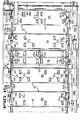
- the cleanout system 22 includes a control circuit 34 (Figs. 3 and 21) for selectively actuating the turnover device Z4.
- the control circuit receives input signals from the two photodetector units 36a and 36b that are so located over the end transfer path between the lanes L2 and Ll that they respectively view the inner and outer rows of mold cups 12a of the mold strip 12 which is in transit in such end transfer path to the starting position of filling lane Ll.
- the control circuit thus receives signals from the photodetector units that indicate that a missed product is in any cup in the scanned rows and provides a signal to actuate the turnover device 24 to invert that (and only that) mold strip that contains a missed product.
- Such selective mold strip cleaning enables the freezing apparatus 11 to normally recirculate the mold strips in the horizontal plane of movement of the strips without inverting the strips, whereby minor residual amounts of confection material left in the mold cups after extraction may be reused. That is to say, the small residual amount of melted confection material that is normally left in a mold cup as a result of the heat used to facilitate separation of product from the mold (as described hereinbefore) is not automatically ejected or rinsed from the mold cup but is recombined at the filler 14 with the next confection material deposited into the cup.
- a switch SW1 Fig. 21
- a switch SW1 may be set so that all of the mold strips are successively inverted by turnover device 24 and rinsed by hot water from the wash.nozzles 30.
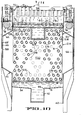
- the freezing apparatus 10 will be seen to include a tubular frame 40 adapted to support two tanks 42 and 42' (Fig. 11) above the floor. It will be noted that the components of the tank 42' that are similar to the like components of tank 42 are given a prime designation.
- the two tanks are supported on the frame adjacent each other with walls 48 and 48' sandwiched between the tanks (Figs. 10 and 11).
- Each tank includes end walls 52 and 60 (Figs. 8 and 15), a bottom wall 54 (Figs. 8 and 10), and side walls 56 and 58 (Fig. 10).
- the tank side walls include inwardly tapered portions 62 and vertical upper end portions 64.
- An exterior wall 66 that extends the length of the apparatus is mounted between the tubular frame and the outermost tank side wall 56 (Figs. 10 and 11).
- An opening 55 (Fig. 10) is formed longitudinally at the center of the bottom wall 54 of each tank, and a trough 70 is mounted to the bottom wall 54 below such opening to receive refrigerated brine and direct it back to a pump 72 as will be described hereinafter.
- the mold strips 12 are pivotally and detachably received on carriers or cradles 74 adapted to transport the mold strips in a horizontal plane through the aforementioned rectangular path and over the tanks 42 and 42', with the mold strips being closely adjacent to each other and extending transversely of their direction of travel in the filling and extraction lanes Ll and L2.
- the cradles are intermittently driven, or indexed, over the tank 42 in the filling lane L l by the pair of parallel transversely spaced conveyor or indexing screws 76 and 78 (Fig. 3), and the cradles are indexed through the lane L2 over the tank 42' by the pair of parallel indexing screws 80 and 82.
- the end transfer conveyor screw 84 which screw is perpendicular to and above the ends of screws 76-82 (Fig. 12A).
- the screw 84 pushes a single cradle laterally from engagement with the conveyor screws 76, 78 into engagement with the conveyor screws 80, 82 (Fig. 3).
- the other end transfer conveyor screw 86 is provided at a right angle to the indexing screws 80, 82 to push the cradle that has been brought into engagement therewith laterally into engagement with the screws 76 and 78 so that it may be recirculated through the rectangular path of travel.
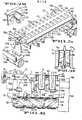
- each mold strip has an identical construction and includes two rows of mold cups 12a.
- the illustrated mold cups have tapered rectangular cross-sectional configurations suitable for producing ice cream bars.
- the two rows of cups are formed in the mold strips so that the relatively wide side walls 88 of the cups oppose each other in a face-to-face relationship at uniform, relatively close intervals along the length of the mold strip (Fig. 5).
- the relatively narrow end walls 90 of the mold cups extend longitudinally of the mold strip.
- This mold cup arrangement minimizes the overall width of the freezing apparatus 11.
- the sticks S are normally inserted so that their flat faces extend in the direction of travel of the mold strips (Fig. 6).
- Each mold strip 12 includes a flat rectangular top wall 92 from which the mold cups 12a depend, a forward or upstream side wall 94 (Fig. 7A) extending downwardly from the leading edge of the top wall, and a rearward or downstream side wall 96 extending downwardly from the trailing edge of the top wall.
- the downstream side wall 96 of each mold has a flange or lip 98 extending rearwardly from the lower end thereof, and the upstream side wall 94 of each mold terminates in a plain straight edge 100.
- the flange 98 underlies and overlaps the edge 100 when the molds are carried through the freezing sections of the apparatus over the freezer nozzles 17 and 17'.
- This overlapping flange configuration provides a baffle for preventing brine B (Fig. 9) from being sprayed upwardly between the molds, to thereby contaminate the confections C in the mold cups 12a.
- each mold strip 12 is detachably mounted to the cradles 74 so that they may be conveniently removed and so that other mold strips for producing a different type of confection may be quickly installed on the cradles.
- each mold strip is pivotally mounted on its cradle so that the cups 12a normally depend from the top wall 92 and so that it may be pivoted 180° in one rotative direction by the-turnover device 24 and thereafter in the opposite direction by the turn-back cam 26.
- each cradle will be seen to include opposed leg plates 102 and 104 that have generally triangular upper ends. The lower ends of the leg plates 102 and 104 are fixed to feet or slide plates 106 and 108, respectively.
- the outer edges of the slide plates are received in grooves formed in a pair of plastic guide tracks 110 and l12 that are attached to the walls 66 and 48, respectively (Fig. 13).
- Tracks 110' and 112' are mounted to the walls 48' and 66' to guide the cradles above the conveyor screws 80 and 82. It may be noted that the guide tracks do not support the entire weight of the cradles; the cradles are also slidably supported in the lanes Ll and L2 on plastic support strips or rails 136 and 138 and 136'and 138' (Fig. 13), respectively (as shall be described).
- the cradles 74 further include rounded lugs 107 and 109 (Fig. 6) that vertically depend from the slide plates 106 and 108, respectively, and rounded lugs 103 and 105 (Figs. 5, 6) that project horizontally in opposite directions from the leg plates 102 and 104, respectively.
- the lugs 107 and 109 of a cradle are respectively received in the grooves 210 of the indexing screws 76 and 78, respectively, when the cradle is in the filling lane Ll, and such lugs are similarly received in the grooves of the indexing screws 80 and 82 as the cradle is propelled through the extraction lane L2.
- the depending lugs are arranged so they project vertically downwardly over the centerline of the indexing screws.
- the lug 103 is, as shown in Figure 12A, mounted to extend horizontally through the centerline of the end transfer screw 84 to enable the screw to push the cradle from the filling lane to the extraction lane.
- the lug 105 (Fig. 14) of a cradle will be brought into engagement with the end transfer screw 86 when the cradle has been indexed into the downstream end or transfer position in the extraction lane L2.
- the leading edges of the base plates 106 and 108 of a cradle 74 are received in a groove in an outer guide track 142 when the cradle is indexed to the downstream ends of the screws 76 and 78 and into engagement with the end transfer screw 84.
- a further guide track 144 (Fig. 14) is also mounted to the end wall 60 to extend horizontally to support the base plates 106, 108 as the associated mold strip is laterally transferred by the screw 86.
- the inner edges of the slide plates are received in inner tracks 141 that are mounted along the side walls 56 and 58 of the tank 42. Tracks similar to tracks 141 are mounted at the ends of the lanes Ll and L2 to guide the cradles in the end transfer legs. .
- Each cradle 74 further comprises a shaft 114 (Fig. 4) that is rigidly connected between the leg plates 102 and 104. fne mold strips 12 are rotatably received on the shafts 114.
- the means for detachably connecting a mold strip 12 to a cradle 74 is illustrated in Figures 4 and 7B.
- Each mold strip has end walls 116 and 118 and a central flange 120 (Fig. 4).
- the end wall 118 and the flange 120 have slots formed centrally therein with collars 122 and 124 being mounted on shaft 114 to be received in the rounded upper portions of the slots.
- the end wall 116 has a key hole slot 126 formed therein so that such end wall-is adapted to be received on the inner end of a bushing 128 affixed upon the end of shaft 114.
- a lug 130 extends radially from the bushing at a position spaced from the' innermost end of the bushing upon which the end wall 118 is received, the lug being affixed to the bushing to extend downwardly and forwardly in the direction of travel of the mold strip in the filling lane Ll.
- Parallel grooves or notches 131 are formed in the circumferential face of the bushing just outside of the lug, such grooves being inclined from the horizontal and parallel to the lug.
- the straight lower part of the key hole slot 126 is parallel to the mold cups. Accordingly, to remove a mold strip from its cradle, the mold strip must be rotated clockwise until the straight part of the key hole slot 126 is aligned with the lug 130. Then, the mold strip may be pulled over the lug to align the end wall 116 within the grooves 131 so that the mold strip may be lifted from the cradle.
- the mold strips 12 and cradles 74 are slidably supported in the filling lane Ll upon plastic support rails 136 and 138 that are horizontally mounted in a parallel relationship to the upper end portions 64 of the side walls of the tank 42.
- horizontal support rails 136' and 138' are mounted to the side walls of the tank 42' (Fig. 13) to support the cradles in the extraction lane L2.
- the support rails 136, 138 are so spaced above the guides 110, 112 that the weight of the cradles and mold strips is substantially borne by the support rails. It is noted that with the cradles and mold strips so supported, the drive pins 107, 109 remain elevated from the bottoms of the grooves in the indexing conveyor screws 76-82.
- the mold strips 12 are prevented from tipping on the associated cradles 74 (except in the mold cleaning area) by means of dowel pins that extend outwardly of the strips and that ride on the support rails 136, 138.
- dowel pins 140 and 142 project outwardly of the end wall 118 of each mold strip at the height of a.bushing 141 mounted on the adjacent end of the cradle shaft 114 and the dowel pins 140, 142 and the bushing 141 (Fig. 4) ride on the inner rail 138 when moving through lane Ll.
- the opposite end wall 116 of the mold strip has a relatively longer dowel pin 144 extending therefrom at the height of the bushing 128, and such bushing and dowel pin 144 ride on the outer rail 136 in lane Ll.
- the rails 136 and 138 start at positions adjacent the turn-back cam 26 (Fig. 15) to support the mold strips as they are carried forwardly therefrom.
- the outer track 136 extends to near the end wall 52.
- an opening 143 is formed in the inner side walls 58, 56' of each tank 42 and 42' and in the central walls 48 and 48' to permit the molds to be laterally transferred therethrough, with the inner rails 136' and 138 extending to the opening 143.
- a first pair of short support rails 150 and 152 (Figs. 15 and 16) are provided to support the mold strips until the long dowel pin 144 is received in the yoke or channel 154 of the turn-over device 24.
- the length of channel 154 is equal to the width of a mold strip so that when the turn-over device 124 is not actuated, the mold strip is guided by the channel until the pins thereof are supported on a further pair of rails 160 and 162 which then guide the molds to the turn-back cam assembly 26.
- the mold strip is thereafter guided by the turn-back cam assembly through pin 144 until it is again supported on the rails 136 and 138.
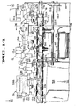
- the construction of the indexing conveyor . screws 76-86 and the drive assembly for simultaneously and continuously driving such screws will now be set forth.
- the conveyor screws 76-86 include shafts 176-186 respectively, (Figs. 3, 12A and 13) extending from their ends, and such screw shafts are received within and supported by bearings 185 (Figs. 11, 12A and 15).
- the arrangement for synchronously and continuously rotating the conveyor screws includes a motor 187 connected through a right-angle speed reducer 188 to a chain 190. Chain 190 is entrained on sprockets connected to the shafts 178 and 182 to drive the screws 78 and 82 in the same direction.
- the chain 190 also engages the underside of a sprocket 180a at the end of the shaft 180 of the screw 80.
- a further chain 192 is entrained between a further sprocket on the shaft 180 and a sprocket at the end of the shaft 176.
- Power for driving the end transfer screw 86 is provided by a right-angle gear box 194 connected to the shaft 182 and a chain 196 entrained between a sprocket on the output shaft of the right-angle gear box 194 and the shaft 186 of the screw 86.
- power for driving end transfer screw 84 is provided through a gear box 198 connected to the shaft 176 of the screw 76 and a chain 200 entrained between the output shaft of the gear box 198 and the shaft 184 of the transfer screw 84.
- the right-angle gear boxes 194, 198 and the sprockets on the gear boxes and shafts 186 and 184 are arranged to cause the end transfer screws 84 and 86 to rotate three times faster than the indexing screws 76-82 and to transfer the mold strips-12 in the end transfer legs in approximately two revolutions of the indexing screws 76-82. That is, the end transfer screws are adapted to transfer a cradle and mold strip in two indexing movements of the cradles in the lanes Ll and L2, as shall now be described.
- the grooves 210 of indexing conveyor screws 76-82 are configured to drive the cradles 74 and attached mold strips 12 in an intermittent manner.
- the grooves have continuous configurations with dwell sections 210a formed therein (Fig. 6) to cause the mold strips to dwell at the filler 14, stick inserter 16, pre-extractor 21 and extractor assembly 18 and helical sections 210b (Fig. 6) between the dwell sections adapted to convey the mold strips with a controlled, smooth acceleration which prevents the confection material in the mold cups 12a from spilling over the tops of the mold cups.
- the grooves in the indexing conveyor screws are adapted to maintain the mold strips in closely spaced relation " when they are conveyed over the freezer nozzles 17 and 17' of the cooling system within the tanks 42 and 42', respectively. By keeping the mold strips in a precise closely spaced relationship, brine is prevented from being sprayed upwardly between the mold strips by the overlapping edge configuration shown in Figure 7A, as previously explained.
- the indexing conveyor screws 76 and 78 include relatively steep helical groove sections 210c (Fig. 12A) which are designed to separate a cradle and mold strip from the trailing mold strip just prior to reaching the lateral transfer at the end of lane Ll.
- the grooves 210 are formed in the screws 76 and 78 (and also in 80 and 82) to spiral in opposite rotative directions around the screws.
- the dwell groove portions 210a (Fig. 6) of the indexing conveyor screws are spaced uniformly along the length of the screws 76-82 in the vicinity of the freezer nozzles 17 and 17' as well as at the various stations (as explained previously).
- the distance between dwell grooves 210a is equal to the distance between the centerlines of mold cups 12a; in the present embodiment, since the mold cups are spaced by 3 inches, the dwell grooves are accordingly spaced by 3 inches to cause the cups to index forwardly 3 inches at a time. In such an arrangement, the mold strips are indexed forwardly every two seconds. Accordingly, since the mold strips have 12 cups in each row of cups thereof, 12 frozen confections are produced by the frozen confection apparatus 10 of the present invention every 2 seconds.
- FIG. 12A The configuration of the indexing conveyor screws 76-82 in the vicinity of the end transfer positions is shown in Figure 12A.
- groove portions 210c are formed to slope forwardly at a greater angle from the vertical to accelerate the cradle and mold strip in such position to thereby separate it from the trailing mold strip by the time the cradle and the strip arrive at the end transfer position.
- a dwell groove portion 210d is formed at the ends of the groove portions 210c, and such dwell portions 210d extend substantially around the perimeter of the screws to permit the cradle to be laterally transferred while engaged in such dwell groove portions.
- relatively long dwell grooves 210e (Fig.
- the distance between the end dwell grooves 210d and the adjacent dwell grooves 210a is, for example, 6.5 inches to initially allow a 6.5 inch spacing between a mold strip in the end transfer position and the trailing mold strip (Fig. 12A) .
- the strip in the end transfer leg will have advanced about half-way toward the other lane of the freezing apparatus, and the trailing mold strip will have advanced 3 inches.
- there will still be a 0.5 inch spacing between the end transfer mold strip and the adjacent strip in the indexing cycle that follows the configuration shown in Figure 12A.
- the groove configuration of end transfer screws 84 and 86 is shown in Figure 13 with respect to the screw 84.
- the grooves 212 have a uniform helical shape with dwell portions 212a and 212b at their ends.
- the end transfer screws are driven at 3 times the speed of the screws 76-82, and the grooves 212 are formed at a greater angle with the vertical than the grooves 210 in the indexing screws to rapidly accelerate the mold strips. It is noted that since the narrow dimensions of the mold cups 12a are in the direction of travel through the end transfer leg from lane Ll to lane L2, the increased acceleration exerted thereon will be less likely to 'cause confection material to spill out of the cups.
- the tendency for the confection material to spill depends on the viscosity of the material, which, in turn, depends on its freezing rate.
- the confection material in the mold cups is still quite flowable at the end of the filling lane, but spilling is avoided as a result of the transverse orientation of the cups in the lateral transfer leg.
- the design of the indexing conveyor screws 76 and 78 in the vicinity of the cleaning area is illustrated in Figure 14.
- the screws in such area are designed to rapidly transfer each cradle 74 and mold strip 12 from the end transfer position forward through a relatively large distance to a dwell position directly above the defroster nozzles 28.
- the cradle and mold strip are indexed forwardly and are caused to dwell in a position so that the mold may be inverted by the turn-over device 24.
- the mold strip and cradle are indexed forward so that the leading row of mold cups 12a of the mold are situated directly above the wash nozzles 30, which nozzles may be operated to wash the mold cups.
- the cradle and mold strip is indexed so that the leading row of maid cups is positioned relative to the air-jet nozzles 32 so that any missed product may be removed from the first row of mold cups in the inverted mold strip.
- the indexing screws are shaped to index the inverted mold strip forward and to dwell while the trailing row of cups is subjected to the air jets.
- the cradle and mold strip is indexed forwardly and is caused to dwell just upstream from the turn-back cam assembly 26.
- the mold strip is driven through the cam block assembly 26 through a relatively large distance to reinvert those mold strips that were inverted by the turn-over device 24, thereby assuring that all mold cups open upwardly.
- the screws 76, 78 are shaped to index a mold forwardly through three dwell positions to a position underlying the nozzles of the filler 14.
- the jet freezing system is the subject of a patent application that is filed concurrently herewith and is entitled, Freezing Apparatus For Freezing Confection Material, such patent application being filed by R. J. Billett et al and being identified by Attorney's Docket No. 8879.
- the freezer nozzles 17 and 17' comprise bores formed in transversely extending nozzle manifold bars 200 that are affixed to a square header tube 202 extending longitudinally of the tank.
- the nozzle bores 17 are formed in each manifold bar at uniform intervals so that the jets of brine B are directed upwardly therefrom midway between the mold cups 12 and against the flat bottom surfaces of the top wall 92 of the mold strip that are between the wider side walls 88 of the mold cups. Since brine at freezing temperatures is relatively viscous, the brine flows smoothly down the outer surfaces of the cups to absorb heat from the mold cups at a high rate of heat transfer.
- the manifold bars 200 are positioned on the header tube 202 at uniform intervals adapted to cause the jets of brine B to impact the mold strips between mold cups in a single row thereof when the cradles and mold strips are in their dwell positions (Fig. 8).
- the manifold bars 200 are positioned at uniform intervals, and the indexing conveyor screws 76-82 are arranged to cause the mold strips to dwell with the centerlines of the cups situated directly over the spray bars so that the jets of brine B impinge perpendicularly against the upper wall of the mold strip exactly between the mold cups.
- the indexing conveyor screws are adapted to keep the mold strips at the same close spacings as they are indexed over the brine jets to avoid any possibility of brine contamination.
- the screw conveyor arrangement maintains such mold strip spacing even after continued operation of the apparatus.
- the brine pump is mounted vertically to the end wall 52 and has a central shaft 204 having an impeller 206 (dotted outline) at the lower end thereof disposed below the surface level of the brine.
- Both brine pumps 72 and 72' are driven by a single motor 208 that is mounted between the pumps, with a drive belt 211 extending between the motor and the pump 72 and another drive belt 211' being connected to the pump 72'.
- Brine flowing from the mold strips is eventually collected in the bottom of the respective tank 42, 42' and flows through the channel 70, 70' thereof into an elbow 213, 213' that is connected between the channel 70, 70' and the pump 72, 72' (Fig. 11).
- a tubular heat exchanger assembly 214 Positioned within each tank below the mold strips 12 and the manifold bars 200 is a tubular heat exchanger assembly 214 (Figs. 8-10).
- brine which has flowed down the mold cups 12a trickles over the heat exchanger tubes 216, whereby the brine is cooled to a suitable low temperature.
- the cold brine is then. collected, circulated through the trough 70, 70' and pumped by the pump 72, 72' back into the associated header tube 202.
- Each tubular heat exchanger assembly 214 consists of a plurality of straight metal tubes 216 mounted in parallel between rectangular header boxes 218 and 220 (Fig. 8) that are mounted between the side walls of the associated tank.
- a heat exchange medium such as liquid ammonia is pumped through an inlet conduit 222 into the upstream header box 220, and gaseous ammonia is withdrawn from the downstream header box 214 through a conduit 223.
- the conduits 222, 223 are connected to the refrigeration system of the facility in which the frozen confection producing apparatus 10 is installed.
- the confection freezing apparatus 11 generally includes insulation material applied to the outside walls of the brine tanks 42, 42'. However, for purposes of clarity, such insulation is not shown in the drawings.
- the turn-over device 24 comprises a pneumatic rotary actuator 240 (Figs. 14-17) that is mounted at the top of the exterior side wall 66.
- the rotary actuator includes a shaft 242 (Fig. 14) that is aligned with the shaft 114 of a mold strip 12 to be inverted (Figs. 15 and 17) when such mold strip dwells in the position of the actuator.
- the channel 154 of the turn- over device is mounted upon the shaft 242 and is initially horizontally disposed so that the dowel pin 144 of the mold strip will slide from the end of the support rail 150 into the channel (Fig. 15).
- the actuator 240 is adapted to rotate the channel 154 through 180° so that upon the next index movement forward, pin 144 will slide from the channel onto the support rail 160.
- the actuator 240 includes an electric solenoid which, when energized, causes the actuator to rotate the channel 180° and to hold the channel arm in such position until the solenoid valve is de-actuated.
- the defroster sprayer nozzles 28 are incorporated in a defroster manifold 250 which extends transversely of the filling lane Ll at the dwell position between the end transfer position and the turn-over position.
- the defroster manifold 250 is supported at such position by a bracket 252 (Fig. 14) mounted between the side walls of the brine tank 42.
- Defroster nozzles 28 are arranged in three rows at uniform spacings so that the nozzles are located directly bellow the mold cups 12 B f .
- Hot water is supplied to the manifold through a conduit 254 that is connected to a pump (not shown), and a solenoid operated valve 256 is connected in the conduit 254.
- the valve 256 is operated from a control circuit (not shown) that, in turn, receives a timing pulse from the shaft encoder 258 (Fig. 3) to open the valve every other cycle to cause the hot water to spray against the underside of a mold strip 12 when the strip dwells at the first dwell position after the start of the filling line. It will be understood that a mold strip is positioned above the sprayer nozzles only upon every other revolution of the indexing screws 76 and 78 since it takes two cycles for a mold strip to be transferred between the mold strip spacing distance.
- the wash nozzles 30 are incorporated in a smaller wash manifold 260 (Fig. 14). Wash nozzles 30 are also arranged in three rows but at closer spacings in the direction of travel of the mold strips so that they direct hot water sprays into the mold cups 12a of a single cup row of an inverted mold strip 12 (Fig. 14). The wash nozzles 30 will be understood to be transversely spaced so that they are aligned with the individual mold cups 12a. Hot water is selectively pumped to wash manifold 260 through a conduit 262 connected to the pump (not illustrated) to which the defroster manifold 250 is connected, and a solenoid operated valve 264 is installed in the conduit 262.
- valve 264 The solenoid for valve 264 is directly connected to another switch in the control circuit so that hot water may be sprayed on each revolution of the conveyor screws while a row of inverted mold cups is directly over the wash manifold.
- the solenoid . operated valve 264 is normally set to prevent washing during regular operation of the apparatus wherein only those mold strips having missed product therein are cleaned.
- all of the mold s'_rips are successively inverted, and the valve 264 is cyclically actuated to successively clean all of the rows of mold cups of the inverted mold strips.
- the air-jet nozzles 32 comprise tubes connected in parallel relationship to a manifold 270 mounted on a support bracket 272 (Fig. 14).
- the air-jet nozzles are transversely spaced and inclined from the vertical so that high velocity air blasts A (Fig. 14) are directed therefrom into a row of inverted mold cups 12a.
- the air jets are directed upwardly along the leading end walls 90 of the mold cups to facilitate removal of the missed product MP (Fig. 14).
- Such product drops onto a take-away conveyor 274.
- High pressure air is provided to the manifold 270 through a tube 276 having a solenoid operated valve 277 therein which is also controlled, by a switch in the control circuitry that receives input from the shaft encoder 258.
- turn-back cam assembly 26 is provided to automatically invert any mold strip 12 that has previously been inverted by the turn-over device 24.
- the cam assembly 26 operates automatically on the principle that only when a mold strip is oriented on a cradle 74 so that pin 144 is at the forward end thereof (i.e., meaning that the mold strip is inverted) will the mold strip be reinverted by the cam assembly.
- the cam assembly includes a rectangular plastic block 280 that is vertically mounted by a bracket 282 to side. wall 66 (Fig. 15).
- a small block 284 (Fig. 18) is provided upstream of the block 280 to guide the pin 144 of a mold strip into a groove 286 formed in the inner surface 288 of the cam block 280.
- Cam groove 286 includes a horizontal inlet portion 286a that communicates with a continuous loop portion 286b adapted to cooperate with the pin 144 of an inverted mold strip to upright the strip.
- the cam block is cut away below a horizontal edge 287 and a straight bar 290 (Figs. 15, 20) is horizontally mounted to block 280 contiguous with the lower edges of the inlet portion 286a.
- the edge 287 and bar 290 form an horizontal exit portion 286c that is aligned with the inlet portion 286a and that is adapted to guide the pin 144 onto the support rail 136 (Fig. 15).
- a lever 292 is freely pivotally mounted on a pin 294 between the bar 290 and cam block 280.-
- the lever has a downstream end 296 that is relatively lighter than the upstream end 298 thereof so that the downstream end is normally tilted upwardly into the downstream exit groove portion 286c (Fig. 20).
- the upstream end 298 of the lever has a wedge shape . adapted to guide the pin 144 of a mold strip from the groove portion 286a upwardly into the groove portion 286b when it is tilted upwardly by the pin 144 of the preceding mold strip to block entrance into exit groove portion 286c.
- the distance between the trailing and leading ends 296 and 298 of the lever is such that when the pin 144 of an inverted mold strip 12 is above the upstream end 298, the pin 144' of the preceding mold strip l2' will be resting on the downstream end 296 to tilt the lever so that the pin 144 will be directed upwardly into the cam groove portion 286b.
- the pin 144 of a mold strip enters the groove portion 286b, the mold strip is inverted as its cradle 74 is carried forwardly.
- the distance between the pin. 144 of two non-inverted mold strips Fig.
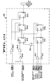
- the electronic control circuit 34 for selectively actuating the turn-over device 24 when a missed product is viewed in any of the mold cups 12a of a mold strip 12 is shown in Figure 21.
- the control circuit 34 receives input signals from the photoelectric detector units 36a and 36b (Figs. 3, 14 and 15).
- photodetector units 36a and 36b are aligned with the two rows of cups of a mold strip as it is transferred in the end transfer leg from the extraction lane L2 back to the filling lane Ll.
- the photodetector units each include an infrared light source and a photoelectric detector, and each unit is mounted at an angle from the vertical and at a height above the mold strip in the end transfer leg so that .
- the photodetector units 36a, 36b are set to generate a high output signal only when the confection material is near the upper top end of the mold cups, and, on the other hand, they will not produce an output signal when only a minor amount of confection material is deep within the mold cup.
- a suitable commercially available photodetector unit is the Banner Multibeam Photodetector manufactured by the Banner Engineering Corporation of Minneapolis, Minnesota.
- Another photoelectric detector unit 302 is mounted to the end wall 60 (Fig. 15) in the vertical plane of the detectors 36a and 36b and is directed toward the mold cups to produce a signal that indicates that a mold cup is present to be tested.
- a further photoelectric detector unit 304 is mounted to the end wall 60 at the outer side of the filling lane Ll (Figs. 14 and 15) to produce a signal that indicates that the mold strip has been completely transferred into the filling lane.
- the output signals from the photodetector units 36a and 36b are fed to a NAND gate 310 so that a high signal is fed from the gate to a flip-flop 314 when missed product is sensed in either of the two cups viewed by the units 36a and 36b.
- the output of the photodetector unit 302 is first inverted by inverter 312 and then fed to the clock input of the flip-flop 314 so that the flip-flop passes the status of the photoelectric units 36a, 36b when the two mold cups are within the view of units 36a and 36b.
- the output of the flip-flop 314 is fed to a further flip-flop 316 which latches its output high when a missed product is sensed in a mold cup.
- the output of the latching flip-flop 316 is fed to a first register of a series of three registers 318, 320, and 322.
- An OR gate 324 is interposed between the latching flip-flop 316 and register 318, and such OR gate also receives a signal from the wash select switch SW-1 which, when actuated, causes the turn-over device 24 to invert all mold strips, as shall be described hereinafter.
- a high signal from the photodetector unit 304 indicates that a mold strip scan by the photodetector units 36a, 36b and 302 is complete and that the scanned mold strip is in a position to be transferred into the mold cleaning area.
- the output from photodetector 304 is fed through an inverter 326 to a NAND gate 328 which squares the input signal and feeds it to the clock terminal of the first shift register 318.
- the clock terminals of the second and third shift registers 320 and 322 are connected to the output timing signal from the shaft encoder unit 258.
- the timing signal is fed from the encoder unit 258 through a NAND gate 330 to the registers 320 and 322.
- the three shift registers 318, 320 and 322 delay the missed product signal from the flip-flop 316 for two encoder pulses from the time that the mold strip reaches the inlet of the feeding lane Ll; that is, the registers delay the missed product signal for two complete revolutions of the indexing screws 76 and 78 until the scanned mold strip with a missed product is brought into engagement with the turn-over device 24.
- a low signal indicative of a missed product is passed by the register 322 to the solenoid operated valve of the actuator 240 of the turn-over device 24, and the actuator will be energized to invert the mold strip.
- the latching flip-flop 316 is provided to hold such inverting signal until after the indexing screws have rotated through another revolution to advance the inverted strip out of the channel 154 of the turn-over device. It will be seen that the flip-flop 318 will be reset by an output signal from the second stage register 320. In turn, the flip-flop 316 is cleared by a latch reset signal provided by the register 318.
- the control circuit 34 further includes means for causing the turn-over device 24 to be actuated every second cycle to invert all of the mold strips 12 so that they may be washed. This is accomplished by the wash switch SW-1 which, when actuated, provides a high signal to the OR gate 324, which signal is passed through register 318 when the end transfer photodetector unit 304 is actuated by each successive mold strip_12. Also; the wash valve 264 may then be opened every cycle to rinse the inverted mold cups one row at a time.
- the apparatus 10 is capable of producing frozen confections at a high rate of 30 rows of confections per minute. Such high rate of production is possible even though the freezing apparatus 11 occupies a relatively small floor area afforded by the compact rectangular conveying arrangement. Also, the freezing apparatus 11 requires a minimum number of mold strips 12 since only those five mold strips in the cleaning area and the single mold strip transferred from the extraction lane L2 to the filling lane Ll (and vice versa) are out of active use at any one time.
- the mold strips are returned from the extraction lane to the filling lane without necessarily being inverted, minor residual amounts of confection material left within the mold cups 12a after extraction of the confections is not wasted but is recombined with the new confection material deposited by the filler 14. Also, a minimal time elapses between extraction and filling so that such minor amounts of product remaining after extraction are not subject to any sanitation or hygiene problems.
- the selective mold cleaning system 22 described herein is adapted to dislodge major amounts of product such as a missed confection MP left in a mold cup when the extractor assembly 18 fails to operate or when the 'stick inserter 16 fails to operate properly, thus eliminating the need for an operator to inspect for and remove such missed products.
- the present apparatus includes an efficient means for successively washing all of the mold strips at the end of a work day or when the mold strips are to be removed and a new type of mold strip inserted.
- the preferred conveyor screw drive arrangement of the present invention is adapted to smoothly and rapidly index the mold strips without danger of brine being ejected or otherwise migrating upwardly between the detachable mold strips. Also, the conveyor so smoothly accelerates the mold strips that spill-over of the confection material from the mold cups is avoided, even though the mold cups are operated at a relatively high indexing rate and are rapidly moved through the end transfer legs.
- mold strips can be quickly removed from the carriers or cradles 74, and new mold strips may be readily installed--thus minimizing the down-time of the apparatus when it is desired to set up the apparatus to manufacture a different type of frozen confection.
Landscapes
- Engineering & Computer Science (AREA)
- Life Sciences & Earth Sciences (AREA)
- Chemical & Material Sciences (AREA)
- Food Science & Technology (AREA)
- Polymers & Plastics (AREA)
- Manufacturing & Machinery (AREA)
- Confectionery (AREA)
Applications Claiming Priority (2)
| Application Number | Priority Date | Filing Date | Title |
|---|---|---|---|
| US06/146,931 US4330245A (en) | 1980-05-05 | 1980-05-05 | Apparatus for producing frozen confections |
| US146931 | 1993-10-25 |
Publications (1)
| Publication Number | Publication Date |
|---|---|
| EP0039514A2 true EP0039514A2 (fr) | 1981-11-11 |
Family
ID=22519622
Family Applications (1)
| Application Number | Title | Priority Date | Filing Date |
|---|---|---|---|
| EP81103399A Withdrawn EP0039514A2 (fr) | 1980-05-05 | 1981-05-05 | Appareil pour la fabrication de crèmes glacées |
Country Status (6)
| Country | Link |
|---|---|
| US (1) | US4330245A (fr) |
| EP (1) | EP0039514A2 (fr) |
| JP (1) | JPS572639A (fr) |
| AU (1) | AU6891581A (fr) |
| BR (1) | BR8102752A (fr) |
| DK (1) | DK197381A (fr) |
Cited By (3)
| Publication number | Priority date | Publication date | Assignee | Title |
|---|---|---|---|---|
| EP0649597A1 (fr) * | 1993-10-21 | 1995-04-26 | CARLE & MONTANARI S.p.A. | Installation pour fabriquer des tablettes de chocolat ou des produits similaires |
| EP0661002A1 (fr) * | 1993-12-29 | 1995-07-05 | CARLE & MONTANARI S.p.A. | Moule apte au transport par vis pour moulage de chocolats ou articles analogues |
| IT201800000723A1 (it) * | 2018-01-11 | 2019-07-11 | Renzo Cerboni | Impianto di modellaggio cioccolato senza catene |
Families Citing this family (13)
| Publication number | Priority date | Publication date | Assignee | Title |
|---|---|---|---|---|
| US4576562A (en) * | 1984-04-27 | 1986-03-18 | Fmc Corporation | Apparatus for producing frozen confections |
| US4699583A (en) * | 1985-09-03 | 1987-10-13 | Aigel S.R.L. | Machine for manufacturing frozen food products, in particular ice creams, ice lollies and the like |
| IT1265369B1 (it) * | 1993-12-03 | 1996-11-22 | Carle & Montanari Spa | Frigorifero a funzionamento continuo, per il trattamento di masse contenute in forme, ad esempio masse di cioccolato o simili. |
| EP1734833A1 (fr) * | 2004-04-15 | 2006-12-27 | Tetra Laval Holding & Finance S.A. | Appareil et procede permettant de produire des produits glaces |
| US20090208630A1 (en) * | 2008-02-20 | 2009-08-20 | Young-Soo Koh | Spout pouch ice cream and frozen yogurt manufacturing method and device thereof |
| US8430658B2 (en) * | 2009-01-16 | 2013-04-30 | Propeller, Inc. | Method and apparatus for making frozen comestibles |
| US20110041706A1 (en) * | 2009-08-19 | 2011-02-24 | Whetstone Jr Henry M | Chocolate manufacturing apparatus including walking beam conveyor and associated methods |
| WO2014113532A1 (fr) | 2013-01-16 | 2014-07-24 | Propeller Inc. | Appareil pour préparer des aliments glacés |
| US9272444B2 (en) | 2013-07-18 | 2016-03-01 | Propeller, Inc. | Ice mold |
| US9516889B2 (en) | 2013-09-16 | 2016-12-13 | Idea Boxx, Llc | Automated cleaning system for food processor and method |
| US10368564B2 (en) | 2015-12-11 | 2019-08-06 | Idea Boxx, Llc | Flow balancing in food processor cleaning system |
| CN106937694A (zh) * | 2017-03-15 | 2017-07-11 | 段树军 | 双层冷冻区雪糕生产设备及其模具组件的生产循环方法 |
| MX2023012531A (es) | 2021-04-27 | 2023-10-31 | Hershey Co | Sistema y metodo para transportar moldes de confiteria. |
Family Cites Families (4)
| Publication number | Priority date | Publication date | Assignee | Title |
|---|---|---|---|---|
| US2925052A (en) * | 1953-12-14 | 1960-02-16 | Glass Robert Taylor | Confection machine |
| US2884875A (en) * | 1955-10-17 | 1959-05-05 | Marlin B Rasmusson | Automatic stick-confection mechanism |
| US3648625A (en) * | 1970-06-16 | 1972-03-14 | Robert Taylor Glass | Automatic pickup and enrobing apparatus for stick-type novelties |
| US4209288A (en) * | 1978-06-23 | 1980-06-24 | Fmc Corporation | Frozen confection producing system |
-
1980
- 1980-05-05 US US06/146,931 patent/US4330245A/en not_active Expired - Lifetime
-
1981
- 1981-03-30 AU AU68915/81A patent/AU6891581A/en not_active Abandoned
- 1981-05-01 JP JP6532481A patent/JPS572639A/ja active Granted
- 1981-05-04 DK DK197381A patent/DK197381A/da unknown
- 1981-05-05 EP EP81103399A patent/EP0039514A2/fr not_active Withdrawn
- 1981-05-05 BR BR8102752A patent/BR8102752A/pt unknown
Cited By (4)
| Publication number | Priority date | Publication date | Assignee | Title |
|---|---|---|---|---|
| EP0649597A1 (fr) * | 1993-10-21 | 1995-04-26 | CARLE & MONTANARI S.p.A. | Installation pour fabriquer des tablettes de chocolat ou des produits similaires |
| US5591464A (en) * | 1993-10-21 | 1997-01-07 | Carle & Montanari S.P.A. | Molding plant for conveying molds for chocolate or similar products |
| EP0661002A1 (fr) * | 1993-12-29 | 1995-07-05 | CARLE & MONTANARI S.p.A. | Moule apte au transport par vis pour moulage de chocolats ou articles analogues |
| IT201800000723A1 (it) * | 2018-01-11 | 2019-07-11 | Renzo Cerboni | Impianto di modellaggio cioccolato senza catene |
Also Published As
| Publication number | Publication date |
|---|---|
| JPS6113781B2 (fr) | 1986-04-15 |
| DK197381A (da) | 1981-11-06 |
| BR8102752A (pt) | 1982-01-26 |
| US4330245A (en) | 1982-05-18 |
| AU6891581A (en) | 1981-11-12 |
| JPS572639A (en) | 1982-01-08 |
Similar Documents
| Publication | Publication Date | Title |
|---|---|---|
| US4330245A (en) | Apparatus for producing frozen confections | |
| KR920009466B1 (ko) | 빙과의 제조 방법 및 그 장치 | |
| US5343886A (en) | Bottle washer with multiple size carrier | |
| BRPI0712125A2 (pt) | linha de produção intensificada versátil para preparar e empacotar produtos alimentìcios | |
| US4432214A (en) | Device for insertion and feed of products on the plates in a horizontal plate freezer | |
| US3228357A (en) | Apparatus and method for enrobing confections | |
| US3575713A (en) | Method and apparatus for cleaning containers | |
| US4335583A (en) | Apparatus for freezing confections | |
| US2884875A (en) | Automatic stick-confection mechanism | |
| US4577651A (en) | Device for cleaning containers | |
| US4324108A (en) | Apparatus for freezing confection material | |
| US2267789A (en) | Apparatus for freezing food products | |
| US5235996A (en) | Bottle washer with multiple carrier | |
| JPH0242931A (ja) | パン冷却装置 | |
| US4104080A (en) | Apparatus and method for washing and drying reusable containers | |
| US3559563A (en) | Bottling apparatus and method | |
| US2640444A (en) | Automatic baking machine | |
| US3799807A (en) | Automatic case washing system | |
| US2253912A (en) | Bottle washer | |
| US4304085A (en) | Cocktail filling machine and method | |
| JP2021073875A (ja) | 氷菓モールド冷却装置 | |
| JP3030761B2 (ja) | 冷凍麺類専用フリーザー | |
| US7975603B1 (en) | Food processing system | |
| US3189160A (en) | Roller bed conveyor | |
| KR102243639B1 (ko) | 자동 제빙장치 |
Legal Events
| Date | Code | Title | Description |
|---|---|---|---|
| PUAI | Public reference made under article 153(3) epc to a published international application that has entered the european phase |
Free format text: ORIGINAL CODE: 0009012 |
|
| AK | Designated contracting states |
Designated state(s): BE DE FR GB IT NL |
|
| 17P | Request for examination filed |
Effective date: 19820504 |
|
| STAA | Information on the status of an ep patent application or granted ep patent |
Free format text: STATUS: THE APPLICATION HAS BEEN WITHDRAWN |
|
| 18W | Application withdrawn |
Withdrawal date: 19830309 |
|
| RIN1 | Information on inventor provided before grant (corrected) |
Inventor name: ANDERSON, DAVID NORRIS Inventor name: BILLETT, RONALD JESSE Inventor name: EASTER, WILLIAM MAURICE |