EP0038768B1 - Locking device for a pipe coupling incorporating a valve - Google Patents
Locking device for a pipe coupling incorporating a valve Download PDFInfo
- Publication number
- EP0038768B1 EP0038768B1 EP19810420061 EP81420061A EP0038768B1 EP 0038768 B1 EP0038768 B1 EP 0038768B1 EP 19810420061 EP19810420061 EP 19810420061 EP 81420061 A EP81420061 A EP 81420061A EP 0038768 B1 EP0038768 B1 EP 0038768B1
- Authority
- EP
- European Patent Office
- Prior art keywords
- dome
- sluice
- slider
- bolt
- elements
- Prior art date
- Legal status (The legal status is an assumption and is not a legal conclusion. Google has not performed a legal analysis and makes no representation as to the accuracy of the status listed.)
- Expired
Links
Images

Classifications
-
- F—MECHANICAL ENGINEERING; LIGHTING; HEATING; WEAPONS; BLASTING
- F16—ENGINEERING ELEMENTS AND UNITS; GENERAL MEASURES FOR PRODUCING AND MAINTAINING EFFECTIVE FUNCTIONING OF MACHINES OR INSTALLATIONS; THERMAL INSULATION IN GENERAL
- F16L—PIPES; JOINTS OR FITTINGS FOR PIPES; SUPPORTS FOR PIPES, CABLES OR PROTECTIVE TUBING; MEANS FOR THERMAL INSULATION IN GENERAL
- F16L37/00—Couplings of the quick-acting type
- F16L37/28—Couplings of the quick-acting type with fluid cut-off means
- F16L37/38—Couplings of the quick-acting type with fluid cut-off means with fluid cut-off means in only one of the two pipe-end fittings
- F16L37/44—Couplings of the quick-acting type with fluid cut-off means with fluid cut-off means in only one of the two pipe-end fittings with one lift valve being actuated to initiate the flow through the coupling after the two coupling parts are locked against withdrawal
-
- F—MECHANICAL ENGINEERING; LIGHTING; HEATING; WEAPONS; BLASTING
- F16—ENGINEERING ELEMENTS AND UNITS; GENERAL MEASURES FOR PRODUCING AND MAINTAINING EFFECTIVE FUNCTIONING OF MACHINES OR INSTALLATIONS; THERMAL INSULATION IN GENERAL
- F16K—VALVES; TAPS; COCKS; ACTUATING-FLOATS; DEVICES FOR VENTING OR AERATING
- F16K35/00—Means to prevent accidental or unauthorised actuation
Definitions
- the present invention relates to safety valve fittings, that is to say connection devices in which one of the two pluggable elements contains an adjustable shutter member capable of being operated from the outside by the 'user.
- the shutter member is coupled to the mechanism which ensures the locking of the two plug-in elements so that they cannot be separated until the aforementioned member has been brought into the closed position and the interior space of the pipe associated with the element which does not include this member has not been placed in communication with the external atmosphere through a leakage vent.
- the shutter member consists of a rotating plug angularly operated using a cylindrical ring mounted to slide axially on the body of the female element.
- the locking of the two pluggable elements is effected by means of a series of balls controlled radially by a sliding sleeve so as to engage in an annular depression of the male element, this sleeve itself being immobilized axially by a second series balls activated by the operating ring when the plug is in the open position.
- the improvements which are the subject of the present invention are more particularly intended to remedy the aforementioned drawback and to allow the production of a safety valve connection of simple and economical construction and of particularly reliable operation.
- the invention comprises a safety valve connection, of the type comprising two pluggable elements, one of which contains a rotating plug connected to the mechanism for locking said elements so that they cannot be separated while the valve is in the open position, characterized in that the rotary plug has an eccentric bearing for the control of a slide arranged so as to immobilize the cross-moving lock which, in the known manner, ensures the blocking of the two elements of the device to the fitted position.
- the eccentric actuating scope is provided on the part of the plug which is intended to carry the operating key, while the slide cut out from an opening engaged on the aforementioned bearing, is guided longitudinally in a depression formed in the outer wall of the female element of the valve connection, its free end being adapted to engage in a housing provided laterally in the part of the transverse part or latch which protrudes outside of said element.
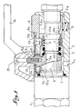
- the body of the female element of the valve connection shown in fig. 1 and 2 is constituted by the assembly of two hollow parts 1 and 2, screwed into one another with the interposition of a fur 1 '.
- a ball valve 3 pierced with a through bore 3a and held between two seal carrier rings 4 and 5.
- a spring 6 which tends to push back a sleeve 7 and to engage it inside the opening 8a of a cylindrical lock 8.
- this lock 8 is movable, under the effect or against a spring 9, inside a transverse housing 2a, of circular section, of the part 2 of the body 1-2; the opening 8a of this lock 8 has a tooth 8b intended to be disposed behind a flange 10a provided on the end piece 10 of the corresponding male element of the connector.
- the rotary plug 3 comprises upwards two superimposed cylindrical surfaces, namely a first 3b which guides the rotation of said plug in part 2 of the body 1-2 and a second 3c which is eccentric with respect to the first and therefore to the transverse pivot axis of the plug in the body 1-2.
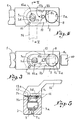
- Each of these bearing surfaces 3b and 3c is equipped with a friction lining or sleeve 11 and the lining of the upper bearing or eccentric boss 3c is engaged in an opening 12a (fig. 3 and 4) formed in a slide 12; it will be noted that this opening 12a is elongated transversely with respect to the axis of the slide, its width being equal to a very slight play near the diameter of the eccentric boss 3c.
- This slide 12 is guided in a longitudinal depression 2b provided in the upper face of the part 2 of the body 1-2 and it is retained in this depression by a button 13 engaged in an axial slot 12b of said slide.
- the plug 3 is extended by a 3d square on which is fixed an operating key or lever 14.
- This lever 14 is fixed in place with an axial screw 15 (fig . 1) and its base cooperates with a pin 16 (fig. 2 to 4) which limits the angular displacement of said lever and of the plug to a value of 90 °. How rac works cord-valve described emerge from the above explanations and are easily understood.
- the device In fig. 2, 4 and 5 the device is shown in the closed position, the bore 3a of the plug 3 and the lever 14 being oriented transversely relative to the axis of the female element.
- the inner sleeve 7 is, by the action of the spring, in the advanced position for which its front edge abuts against the tooth 8b of the latch 8; this sleeve 7 is established at two external diameters and in the advanced position its larger diameter part opposes any transverse movement of the lock 8.
- the user To dissociate the two elements from the open position of fig. 1 and 3, the user must first bring the lever 14 and the plug 3 to the closed position according to FIG. 2, 4 and 5. In doing so, the pipe associated with the male element is placed in communication with the outside through an oblique channel 3e of the plug 3 and a vent 2c of the part 2, which ensures the decompression of the pipe. above, in the manner known per se.
- the lock 8 can be lowered since it is in the high position according to fig. 1, so that the male element is capable of being withdrawn axially from the female element and that we then find our in the position according to FIG. 2.
Landscapes
- Engineering & Computer Science (AREA)
- General Engineering & Computer Science (AREA)
- Mechanical Engineering (AREA)
- Preventing Unauthorised Actuation Of Valves (AREA)
- Quick-Acting Or Multi-Walled Pipe Joints (AREA)
Description
La présente invention a trait aux raccords-vannes de sécurité, c'est-à-dire aux dispositifs de raccordement dans lesquels l'un des deux éléments emmanchables renferme un organe réglable d'obturation susceptible d'être manoeuvré de l'extérieur par l'utilisateur.The present invention relates to safety valve fittings, that is to say connection devices in which one of the two pluggable elements contains an adjustable shutter member capable of being operated from the outside by the 'user.
On sait que dans les dispositifs de ce genre l'organe d'obturation est attelé au mécanisme qui assure le verrouillage des deux éléments emmanchables de façon à ce que ceux-ci ne puissent être dissociés tant que l'organe précité n'a pas été amené en position de fermeture et que l'espace intérieur de la canalisation associée à l'élément qui ne comporte pas cet organe n'a pas été mis en communication avec l'atmosphère extérieure à travers un évent de fuite.We know that in devices of this kind the shutter member is coupled to the mechanism which ensures the locking of the two plug-in elements so that they cannot be separated until the aforementioned member has been brought into the closed position and the interior space of the pipe associated with the element which does not include this member has not been placed in communication with the external atmosphere through a leakage vent.
Dans certains dispositifs connus l'organe d'obturation est constitué par un boisseau tournant manoeuvré angulairement à l'aide d'une bague cylindrique montée à coulissement axial sur le corps de l'élément femelle. Le verrouillage des deux éléments emmanchables est opéré au moyen d'une série de billes commandées radialement par un manchon coulissant de manière à s'engager dans une dépression annulaire de l'élément mâle, ce manchon étant lui-même immobilisé axialement par une seconde série de billes actionnées par la bague de manoeuvre lorsque le boisseau est à la position ouverte. La fonction de sécurité est bien remplie, mais au prix d'une complication notable de la construction et d'une augmentation sensible du prix de revient.In certain known devices, the shutter member consists of a rotating plug angularly operated using a cylindrical ring mounted to slide axially on the body of the female element. The locking of the two pluggable elements is effected by means of a series of balls controlled radially by a sliding sleeve so as to engage in an annular depression of the male element, this sleeve itself being immobilized axially by a second series balls activated by the operating ring when the plug is in the open position. The safety function is well fulfilled, but at the cost of a noticeable complication of construction and a significant increase in the cost price.
Les perfectionnements qui font l'objet de la présente invention ont plus spécialement pour but de remédier à l'inconvénient précité et de permettre la réalisation d'un raccord-vanne de sécurité de construction simple et économique et de fonctionnement particulièrement fiable.The improvements which are the subject of the present invention are more particularly intended to remedy the aforementioned drawback and to allow the production of a safety valve connection of simple and economical construction and of particularly reliable operation.
L'invention comporte un raccord-vanne de sécurité, du genre comprenant deux éléments emmanchables dont l'un renferme un boisseau tournant relié au mécanisme pour le verrouillage desdits éléments de façon à ce que ceux-ci ne puissent être dissociés alors que la vanne est en position ouverte, caractérisé en ce que le boisseau tournant présente une portée excentrée pour la commande d'un coulisseau agencé de manière à immobiliser le verrou à déplacement transversal qui, à la façon en soi connue, assure le blocage des deux éléments du dispositif à la position emmanchée.The invention comprises a safety valve connection, of the type comprising two pluggable elements, one of which contains a rotating plug connected to the mechanism for locking said elements so that they cannot be separated while the valve is in the open position, characterized in that the rotary plug has an eccentric bearing for the control of a slide arranged so as to immobilize the cross-moving lock which, in the known manner, ensures the blocking of the two elements of the device to the fitted position.
Conformément à un mode de mise en oeuvre préféré de la disposition qui précède, la portée excentrée d'actionnement est ménagée sur la partie du boisseau qui est destinée à porter la clef de manoeuvre, tandis que le coulisseau, découpé d'une ouverture engagée sur la portée précitée, est guidé longitudinalement dans une dépression pratiquée dans la paroi extérieure de l'élément femelle du raccord-vanne, son extrémité libre étant propre à venir s'engager dans un logement prévu latéralement dans la partie de la pièce transversale ou verrou qui dépasse à l'extérieur dudit élément.In accordance with a preferred embodiment of the above arrangement, the eccentric actuating scope is provided on the part of the plug which is intended to carry the operating key, while the slide cut out from an opening engaged on the aforementioned bearing, is guided longitudinally in a depression formed in the outer wall of the female element of the valve connection, its free end being adapted to engage in a housing provided laterally in the part of the transverse part or latch which protrudes outside of said element.
Le dessin annexé, donné à titre d'exemple, permettra de mieux comprendre l'invention, les caractéristiques qu'elle présente et les avantages qu'elle est susceptible de procurer:
- Fig. 1 est une coupe axiale d'un raccord-vanne de sécurité établi conformément à l'invention.
- Fig. 2 reproduit fig. 1, le boisseau ayant été supposé amené à la position fermée et les deux éléments du dispositif ayant été dissociés.
- Fig. 3 et 4 sont des vues en plan à plus petite échelle montrant le coulisseau aux deux positions de fig. 1 et 2.
- Fig. 5 est une coupe transversale suivant le plan indiqué en V-V en fig. 4.
- Fig. 1 is an axial section of a safety valve connection established in accordance with the invention.
- Fig. 2 reproduced fig. 1, the plug having been assumed to be brought to the closed position and the two elements of the device having been separated.
- Fig. 3 and 4 are plan views on a smaller scale showing the slide at the two positions of FIG. 1 and 2.
- Fig. 5 is a cross section along the plane indicated in VV in fig. 4.
Le corps de l'élément femelle du raccord-vanne représenté en fig. 1 et 2 est constitué par l'assemblage de deux pièces creuses 1 et 2, vissées l'une dans l'autre avec interposition d'une fourrure 1'. A l'intérieur de la pièce principale 2 est monté un boisseau sphérique 3 percé d'un alésage débouchant 3a et maintenu entre deux bagues porte- joint 4 et 5. Contre la bague 5 prend appui un ressort 6 qui tend à repousser un manchon 7 et à engager celui-ci à l'intérieur de l'ouverture 8a d'un verrou cylindrique 8. A la façon en soi connue dans l'industrie des raccords, ce verrou 8 est mobile, sous l'effet ou à l'encontre d'un ressort 9, à l'intérieur d'un logement transversal 2a, à section circulaire, de la pièce 2 du corps 1-2; l'ouverture 8a de ce verrou 8 présente une dent 8b destinée à venir se disposer en arrière d'une collerette 10a prévue sur l'embout 10 de l'élement mâle correspondant du raccord.The body of the female element of the valve connection shown in fig. 1 and 2 is constituted by the assembly of two
Le boisseau tournant 3 comporte vers le haut deux portées cylindriques superposées, à savoir une première 3b qui assure le guidage de la rotation dudit boisseau dans la pièce 2 du corps 1-2 et une seconde 3c qui est excentrée par rapport à la première et donc à l'axe transversal de pivotement du boisseau dans le corps 1-2. Chacune de ces portées 3b et 3c est équipée d'une garniture de friction ou douille 11 et la garniture de la portée supérieure ou bossage excentré 3c est engagée dans une ouverture 12a (fig. 3 et 4) ménagée dans un coulisseau 12; on notera que cette ouverture 12a est allongée transversalement par rapport à l'axe du coulisseau, sa largeur étant égale à un très léger jeu près au diamètre du bossage excentré 3c. Ce coulisseau 12 est guidé dans une dépression longitudinale 2b prévue dans la face supérieure de la pièce 2 du corps 1-2 et il est retenu dans cette dépression par un bouton 13 engagé dans une lumière axiale 12b dudit coulisseau.The
Au-dessus de la portée excentrée ou bossage 3c le boisseau 3 se prolonge par un carré 3d sur lequel est calé une clef de manoeuvre ou levier 14. Ce levier 14 est fixé en place à l'aide d'une vis axiale 15 (fig. 1) et sa base coopère avec une goupille 16 (fig. 2 à 4) qui limite le déplacement angulaire dudit levier et du boisseau à une valeur de 90°. Le fonctionnement et l'utilisation du raccord-vanne décrit ressortent des explications qui précèdent et se comprennent aisément.Above the eccentric bearing or
En fig. 2, 4 et 5 le dispositif est représenté à la position de fermeture, l'alésage 3a du boisseau 3 et le levier 14 étant orientés transversalement par rapport à l'axe de l'élément femelle. On notera que le manchon intérieur 7 se trouve, de par l'action du ressort, en position avancée pour laquelle son bord antérieur bute contre la dent 8b du verrou 8; ce manchon 7 est établi à deux diamètres extérieurs et à la position avancée sa partie à plus grand diamètre s'oppose à tout déplacement transversal du verrou 8. Comme par ailleurs l'extrémité libre, à profil arrondi, du coulisseau 12 bute contre la partie dépassante du verrou 8, ledit coulisseau est immobilisé axialement, si bien qu'il interdit la manoeuvre du levier 14 puisque cette manoeuvre, par suite de l'engagement de la portée excentrée 3c dans l'ouverture 12a, provoquerait le mouvement axial du coulisseau. Le raccordvanne ne peut donc en aucun cas et même si l'utilisateur tente d'actionner le verrou 8, être amené en position d'ouverture alors que l'élément mâle n'est pas introduit dans l'élément femelle.In fig. 2, 4 and 5 the device is shown in the closed position, the
En fig. 1 et 3 cet élément mâle a été mis en place dans l'élément femelle. La face oblique de la collerette 10a de l'embout 10 a repoussé le manchon 7 à l'encontre du ressort 6, si bien que le verrou 8 ainsi libéré a pu après passage de ladite collerette 10a se déplacer vers le haut sous l'effet de son ressort 9 et que la dent 8b est venue s'enclencher en avant de la collerette précitée, en verrouillant ainsi les deux éléments du raccord-vanne. Il convient d'observer qu'à cette position du verrou 8 le bord libre du coulisseau 12 se trouve disposé en vis-à-vis d'une entaille 8c pratiquée transversalement dans ledit verrou, de telle sorte que ce coulisseau est ainsi libre de se déplacer vers l'avant sous l'effet de la rotation impartie par l'utilisateur au levier 14. Ce dernier peut en conséquence être amené à la position d'ouverture du boisseau 3 pour laquelle l'alésage 3a et le levier sont orientés suivant l'axe du corps 1-2; par contre la manoeuvre du verrou 8 en vue de la dissociation éventuelle des deux éléments est rendue impossible par suite de l'action de blocage exercée par le coulisseau 12 sur ledit verrou.In fig. 1 and 3 this male element has been placed in the female element. The oblique face of the
Pour dissocier les deux éléments à partir de la position ouverte de fig. 1 et 3, il faut en premier lieu que l'utilisateur ramène le levier 14 et le boisseau 3 à la position de fermeture suivant fig. 2, 4 et 5. Ce faisant la canalisation associée à l'élément mâle est mise en communication avec l'extérieur à travers un canal oblique 3e du boisseau 3 et un évent 2c de la pièce 2, ce qui assure la décompression dé la canalisation précitée, à la façon en soi connue. Le verrou 8 peut être abaissé puisqu'il se trouve à la position haute suivant fig. 1, si bien que l'élément mâle est susceptible d'être retiré axialement de l'élément femelle et qu'on se retrouve alors à la position suivant fig. 2.To dissociate the two elements from the open position of fig. 1 and 3, the user must first bring the
La sécurité de fonctionnement et d'utilisation est totale du fait que les deux éléments ne peuvent être séparés avant fermeture de la vanne et qu'il est impossible d'amener celle-ci à la position d'ouverture alors que lesdits éléments ne sont pas emmanchés. La construction est simple et économique, et donne ainsi lieu à une fiabilité parfaite. Il doit d'ailleurs être entendu que la description qui précède n'a été donnée qu'à titre d'exemple et qu'elle ne limite nullement le domaine de l'invention dont on ne sortiait pas en remplaçant les détails d'exécution décrits par tous autres équivalents.Operating and use safety is total due to the fact that the two elements cannot be separated before closing the valve and that it is impossible to bring the latter to the open position when said elements are not fitted. The construction is simple and economical, and thus gives rise to perfect reliability. It should also be understood that the foregoing description has been given only by way of example and that it in no way limits the field of the invention from which one did not depart by replacing the execution details described by all other equivalents.
Claims (5)
Applications Claiming Priority (2)
| Application Number | Priority Date | Filing Date | Title |
|---|---|---|---|
| FR8009563 | 1980-04-23 | ||
| FR8009563A FR2481401A1 (en) | 1980-04-23 | 1980-04-23 | IMPROVEMENTS TO THE SAFETY VALVE CONNECTIONS |
Publications (2)
| Publication Number | Publication Date |
|---|---|
| EP0038768A1 EP0038768A1 (en) | 1981-10-28 |
| EP0038768B1 true EP0038768B1 (en) | 1983-08-31 |
Family
ID=9241434
Family Applications (1)
| Application Number | Title | Priority Date | Filing Date |
|---|---|---|---|
| EP19810420061 Expired EP0038768B1 (en) | 1980-04-23 | 1981-04-22 | Locking device for a pipe coupling incorporating a valve |
Country Status (3)
| Country | Link |
|---|---|
| EP (1) | EP0038768B1 (en) |
| DE (1) | DE3160809D1 (en) |
| FR (1) | FR2481401A1 (en) |
Families Citing this family (4)
| Publication number | Priority date | Publication date | Assignee | Title |
|---|---|---|---|---|
| GB9009730D0 (en) * | 1990-05-01 | 1990-06-20 | Boc Group Plc | Device for filling anaesthetic vaporisers |
| WO1994013990A1 (en) * | 1992-12-07 | 1994-06-23 | Parker-Hannifin Corporation | Push-to-connect coupler with interlocking three-way valve |
| DE102013002223B4 (en) | 2013-02-11 | 2018-03-22 | Armaturenfabrik Franz Schneider GmbH + Co. KG | Ball valve device |
| CN113623475B (en) * | 2021-08-20 | 2023-03-24 | 浙江海洋大学 | Oil pump with connecting pipe convenient to disassemble and assemble |
Family Cites Families (3)
| Publication number | Priority date | Publication date | Assignee | Title |
|---|---|---|---|---|
| GB844258A (en) * | 1957-06-25 | 1960-08-10 | Weatherhead Co | Improvements in or relating to a quick disconnect pipe coupling |
| FR2082006A6 (en) * | 1969-12-17 | 1971-12-10 | Lenoir Christiane | |
| US4181150A (en) * | 1977-09-12 | 1980-01-01 | Gould, Inc. | Lever-type quick disconnect coupling |
-
1980
- 1980-04-23 FR FR8009563A patent/FR2481401A1/en active Granted
-
1981
- 1981-04-22 DE DE8181420061T patent/DE3160809D1/en not_active Expired
- 1981-04-22 EP EP19810420061 patent/EP0038768B1/en not_active Expired
Also Published As
| Publication number | Publication date |
|---|---|
| FR2481401B1 (en) | 1982-03-26 |
| FR2481401A1 (en) | 1981-10-30 |
| EP0038768A1 (en) | 1981-10-28 |
| DE3160809D1 (en) | 1983-10-06 |
Similar Documents
| Publication | Publication Date | Title |
|---|---|---|
| EP0023189B1 (en) | Fitting devices of the quick-acting type for joining conduits | |
| EP0077743B1 (en) | Couplings of the quick-acting type for the disconnectable connection of pipe lines | |
| EP0678697B1 (en) | Quick acting coupling for pipes under pressure and having a control over its disconnection | |
| EP2024219B1 (en) | System for locking a first shaft with respect to a second shaft eliminating clearances between said shafts | |
| FR2577300A1 (en) | RADIAL DISPLACEMENT LATCH LOCKED QUICK CONNECT | |
| EP2439440A1 (en) | Coupling device with locking by threaded clamps and coupling including such a device | |
| WO2021038162A1 (en) | Connecting device, in particular for producing a fluid flow circuit | |
| FR2515307A1 (en) | CLOSING AND LATCHING DEVICE FOR CONNECTING THE REMOVABLE PIPING | |
| EP0038768B1 (en) | Locking device for a pipe coupling incorporating a valve | |
| CH472623A (en) | Pipe connection device | |
| EP3650951B1 (en) | Timepiece comprising a device for locking a valve or a crown | |
| EP0247956B1 (en) | Power-assisted device for bringing together tightly and assembling two paired elements | |
| FR2661231A1 (en) | DEVICE FOR SHUTTING INTERNAL RING DRIVE SHAFTS. | |
| FR2748304A1 (en) | DEVICE FOR COUPLING TWO SHAFTS | |
| FR2866045A1 (en) | Control knob for safety lock of e.g. protective barrier, has spring supported between core and casing through antifriction stop, and two locking units that are engaged to integrate casing and core for controlling opening of lock | |
| FR1487323A (en) | Quick coupling device for joining pipes and the like | |
| EP0401097B1 (en) | Gripping device of a connector | |
| BE1005841A3 (en) | Coupler for safety valve pressure container fluid. | |
| EP0471603A1 (en) | Connector locking device | |
| FR2724687A1 (en) | Manhole cover security lock, esp. for potable water pipeline networks | |
| FR2865014A1 (en) | Drive cable guiding duct maintaining end part for motor vehicle`s gear box, has sleeve that moves on cylindrical section using torsion spring between open position for positioning part in cavity of wall and closed position for locking part | |
| FR2637041A1 (en) | Tamper-proof tap | |
| CH516761A (en) | Device for connecting a flexible pipe to a supply pipe of a gas installation | |
| FR2499520A1 (en) | Cap for vehicle fuel tank - has lock using fixed and moving cup parts and eccentric operated latch | |
| FR2687453A1 (en) | Coupling device with fitted rotating spools for pipelines |
Legal Events
| Date | Code | Title | Description |
|---|---|---|---|
| PUAI | Public reference made under article 153(3) epc to a published international application that has entered the european phase |
Free format text: ORIGINAL CODE: 0009012 |
|
| AK | Designated contracting states |
Designated state(s): CH DE GB LI SE |
|
| 17P | Request for examination filed |
Effective date: 19811015 |
|
| RAP1 | Party data changed (applicant data changed or rights of an application transferred) |
Owner name: S.A. DES ETABLISSEMENTS STAUBLI (FRANCE) |
|
| GRAA | (expected) grant |
Free format text: ORIGINAL CODE: 0009210 |
|
| AK | Designated contracting states |
Designated state(s): CH DE GB LI SE |
|
| PG25 | Lapsed in a contracting state [announced via postgrant information from national office to epo] |
Ref country code: SE Effective date: 19830831 |
|
| REF | Corresponds to: |
Ref document number: 3160809 Country of ref document: DE Date of ref document: 19831006 |
|
| PLBE | No opposition filed within time limit |
Free format text: ORIGINAL CODE: 0009261 |
|
| STAA | Information on the status of an ep patent application or granted ep patent |
Free format text: STATUS: NO OPPOSITION FILED WITHIN TIME LIMIT |
|
| 26N | No opposition filed | ||
| PGFP | Annual fee paid to national office [announced via postgrant information from national office to epo] |
Ref country code: CH Payment date: 19890411 Year of fee payment: 9 |
|
| PGFP | Annual fee paid to national office [announced via postgrant information from national office to epo] |
Ref country code: GB Payment date: 19890430 Year of fee payment: 9 |
|
| PGFP | Annual fee paid to national office [announced via postgrant information from national office to epo] |
Ref country code: DE Payment date: 19890530 Year of fee payment: 9 |
|
| PG25 | Lapsed in a contracting state [announced via postgrant information from national office to epo] |
Ref country code: GB Effective date: 19900422 |
|
| PG25 | Lapsed in a contracting state [announced via postgrant information from national office to epo] |
Ref country code: LI Effective date: 19900430 Ref country code: CH Effective date: 19900430 |
|
| GBPC | Gb: european patent ceased through non-payment of renewal fee | ||
| REG | Reference to a national code |
Ref country code: CH Ref legal event code: PL |
|
| PG25 | Lapsed in a contracting state [announced via postgrant information from national office to epo] |
Ref country code: DE Effective date: 19910101 |