EP0038318B2 - Dispositif de réglage pour le réglage du chauffage d'eau sanitaire pour un ballon de stockage - Google Patents
Dispositif de réglage pour le réglage du chauffage d'eau sanitaire pour un ballon de stockage Download PDFInfo
- Publication number
- EP0038318B2 EP0038318B2 EP81890059A EP81890059A EP0038318B2 EP 0038318 B2 EP0038318 B2 EP 0038318B2 EP 81890059 A EP81890059 A EP 81890059A EP 81890059 A EP81890059 A EP 81890059A EP 0038318 B2 EP0038318 B2 EP 0038318B2
- Authority
- EP
- European Patent Office
- Prior art keywords
- thermostat
- temperature
- water
- heat exchanger
- charging pump
- Prior art date
- Legal status (The legal status is an assumption and is not a legal conclusion. Google has not performed a legal analysis and makes no representation as to the accuracy of the status listed.)
- Expired - Lifetime
Links
- XLYOFNOQVPJJNP-UHFFFAOYSA-N water Substances O XLYOFNOQVPJJNP-UHFFFAOYSA-N 0.000 title claims description 71
- 238000003860 storage Methods 0.000 title claims description 30
- 238000010438 heat treatment Methods 0.000 title description 10
- 238000012546 transfer Methods 0.000 claims description 6
- 239000012530 fluid Substances 0.000 claims 2
- 230000015654 memory Effects 0.000 description 9
- 238000000034 method Methods 0.000 description 8
- 230000001105 regulatory effect Effects 0.000 description 6
- 230000007423 decrease Effects 0.000 description 4
- 230000006870 function Effects 0.000 description 4
- 238000002360 preparation method Methods 0.000 description 3
- 230000001276 controlling effect Effects 0.000 description 2
- 239000002826 coolant Substances 0.000 description 2
- 238000004519 manufacturing process Methods 0.000 description 2
- 238000002156 mixing Methods 0.000 description 2
- 230000006978 adaptation Effects 0.000 description 1
- 230000033228 biological regulation Effects 0.000 description 1
- 238000001816 cooling Methods 0.000 description 1
- 238000013461 design Methods 0.000 description 1
- 230000000694 effects Effects 0.000 description 1
- 238000000605 extraction Methods 0.000 description 1
- 239000013505 freshwater Substances 0.000 description 1
- 239000008236 heating water Substances 0.000 description 1
- 239000008235 industrial water Substances 0.000 description 1
- 238000009413 insulation Methods 0.000 description 1
- 238000013021 overheating Methods 0.000 description 1
- 239000003507 refrigerant Substances 0.000 description 1
- 230000004044 response Effects 0.000 description 1
- 238000013517 stratification Methods 0.000 description 1
Images
Classifications
-
- F—MECHANICAL ENGINEERING; LIGHTING; HEATING; WEAPONS; BLASTING
- F24—HEATING; RANGES; VENTILATING
- F24D—DOMESTIC- OR SPACE-HEATING SYSTEMS, e.g. CENTRAL HEATING SYSTEMS; DOMESTIC HOT-WATER SUPPLY SYSTEMS; ELEMENTS OR COMPONENTS THEREFOR
- F24D17/00—Domestic hot-water supply systems
- F24D17/02—Domestic hot-water supply systems using heat pumps
-
- F—MECHANICAL ENGINEERING; LIGHTING; HEATING; WEAPONS; BLASTING
- F24—HEATING; RANGES; VENTILATING
- F24D—DOMESTIC- OR SPACE-HEATING SYSTEMS, e.g. CENTRAL HEATING SYSTEMS; DOMESTIC HOT-WATER SUPPLY SYSTEMS; ELEMENTS OR COMPONENTS THEREFOR
- F24D19/00—Details
- F24D19/10—Arrangement or mounting of control or safety devices
- F24D19/1006—Arrangement or mounting of control or safety devices for water heating systems
- F24D19/1066—Arrangement or mounting of control or safety devices for water heating systems for the combination of central heating and domestic hot water
Definitions
- the invention relates to a temperature control device for industrial water in a water storage tank, which is heated using a heat exchanger equipped with a primary and a secondary circuit, arranged outside the storage tank and supplied with heat energy on the primary side, the water to be heated being heated in the secondary circuit at the bottom of the storage tank removed and returned by a thermostat-controlled charge pump via the heat exchanger in the heated state on the cover side, with a first thermostat in the storage tank and a second thermostat connected in series with the first thermostat in the region of the cold water zone, the first thermostat closing at a predetermined lower hot water temperature and the The charging pump switches on for the charging process and the second thermostat opens at a predetermined upper hot water temperature and the charging pump to end the charging process turns off.
- the arrangement is essentially the same as that described above, in which case the heat exchanger is connected to the heating circuit of the solar system.
- a memory with a separate heat exchanger is known from DE-A-2 508 135, which is connected on the primary side to a heating system.
- a thermostatically controlled pump is provided on the secondary side, which takes the water to be heated from the storage tank at the bottom, passes it through the heat exchanger, and returns it to the storage tank at the top.
- an electrical heater is provided in the heat exchanger, which enables additional heat supply and thus a certain adaptation to fluctuating operating conditions.
- a combination of such a heat exchanger with a heat pump requires the use of expensive electrical energy and can therefore not be considered for economic reasons.
- DE-B-1 019 792 relates to a heat pump system with a hot water pressure accumulator, the condenser or condenser of the heat pump being designed as a heat exchanger.
- the water is removed from the bottom of the pressure accumulator by heat convection, passed through the heat exchanger and returned in the upper third of the pressure accumulator.
- the refrigerant flowing back to the expansion valve heats the incoming fresh water in a further heat exchanger.
- the characteristic feature is a drain valve, pressure-controlled by the coolant, for the water flowing from the store to the heat exchanger.
- a control device of the type mentioned has become known, in which the first part is arranged in the upper part of a domestic hot water tank and in the lower part thereof the second thermostat connected in series with the first and the first thermostat one
- the charge pump switches on and the second thermostat switches off the charge pump to end the charging process, the first thermostat closing at a predetermined lower hot water temperature and the second thermostat opening at a predetermined upper hot water temperature.
- this publication mentions an embodiment in which the heat exchanger that heats the water in the store can be integrated outside the store, preferably in a boiler that supplies the heat exchanger with thermal energy.
- the disadvantage of the known control device is that, especially when starting, the water is initially supplied to the storage tank at a lower than the desired hot water temperature, which means that zones of cooler water are always recharged.
- an auxiliary pump is switched on by a control element, which is not defined in any more detail, as a result of which a greater quantity of water is conveyed through the instantaneous heater and overheating of the system is avoided.
- the known system does not respond if too cold water flows through line 11.
- the object of the invention is to optimize the generic temperature control device in such a way that the water storage tank, sufficient heat supply in the primary circuit, water is only supplied with a maximum final temperature so as not to disturb the temperature stratification of the water, the process water passing through the heat exchanger only once and the heat transfer performance of the heat exchanger should be optimally used.
- a controlled depending on the outlet temperature of the secondary circuit from the heat exchanger actuator for adjusting or regulating the flow rate is provided, with which the flow rate in the secondary circuit depending on the heat transfer capacity of the heat exchanger is set or It is regulated that the flow rate is a maximum at the outlet temperature above a predetermined value and a minimum at the outlet temperature below this value, a continuously adjustable valve or a charge pump with a controllable drive motor being provided as the actuator.
- a third thermostat which is controlled as a function of the inlet temperature of the primary circuit in the heat exchanger, is arranged when the primary circuit enters the heat exchanger, which is connected in series with the circuit for the charge pump, and for controlling the actuator thereby enabling the charging pump to be switched on by the first thermostat, the third thermostat closing at a predetermined upper temperature of the primary circuit medium.
- the primary circuit is preferably connected to a heat pump, the heat transfer performance of the heat exchanger being coordinated with the heat pump in such a way that the maximum amount of heat given off is transferred to the domestic water at the highest temperature.
- the temperature control device in conjunction with the coordinated heat transfer capacity of the heat exchanger and the delivery rate of the secondary circuit set by means of the actuator, ensures that the temperature of the cold service water drawn at the lowest possible point is increased to the maximum possible final temperature with a single pass of the service water to be heated.
- the storage tank is loaded from above and the separating layer between hot and cold process water moves downwards until the storage tank is no longer charged. There is therefore no undesirable mixing of hot and cold water, as is the case with conventional turbulence due to convection.
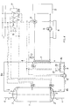
- the pressure-resistant storage container is denoted by 1 and preferably has the shape of a standing cylinder with a curved bottom 2 and a likewise curved lid 3.
- the bottom 2 leads a kaft water supply pipe 4, the inner end of which is opposite a baffle plate 5.
- a distributor plate 7 is also located in the upper part of the storage container 1, near the cover 3.
- the secondary circuit is constructed by the pipe sections 8a, 8b and 8c.
- the pipe section 8a comes from the heat exchanger, generally designated 9, and opens into the cover 3.
- the pipe section 8b extends from the bottom 2 to a charge pump 10 and an adjustable throttle valve 11.
- the invention provides that the flow rate of the secondary circuit of the heat exchanger is controlled as a function of the outlet temperature of the water from the heat exchanger.
- a device for this purpose contains in the secondary circuit an actuator for regulating the flow rate, which is regulated as a function of the outlet temperature of the water from the heat exchanger.
- the flow rate can be regulated continuously or discontinuously, ie for example as a two-point control.
- the thermostats T1, T4 and T2 are provided, the thermostat T1 being arranged approximately in the center and the thermostat T2 on the bottom side of the store.
- the thermostat T4 is arranged when the secondary circuit emerges from the heat exchanger 9.
- the pipe section 8c leads from the throttle valve 11 to the heat exchanger 9.
- the primary circuit consists of a heat pump 13, a circulation pump 14, a priority valve (electromagnetically operable three-way valve) 15, which supplies the heater 16 outside the charging time of the water heater in the application case shown. Furthermore, the thermostat T3 is arranged in the primary circuit, specifically at the entry point of the primary circuit medium into the heat exchanger 9.
- a switching device is designated 17 and contains a relay with a coil 18 and with contacts 19, 20a and 20b open in the idle state.
- the coil 18 is in series with the contacts of the thermostats T1 and T2, which are also in series, at a supply voltage (for example mains voltage).
- thermostat T1 If the temperature of the hot water in storage tank 1 is sufficiently high, the contact of thermostat T1 is open. The contact of the thermostat T2 is closed, because cold water is available from the bottom of the storage tank. If hot service water is withdrawn via the discharge line 6, cold water flows in via the feed pipe 4. As soon as the temperature at the point of the thermostat T1 falls below a predetermined value, the contact of the thermostat T1 closes and thus closes the circuit for the coil 18, so that the contacts 19, 20a and 20b close. The contact 19 serves as a hold contact, i.e. it bridges the contact of the thermostat T1.
- the electromagnetically actuated priority valve 15 is connected directly and, on the other hand, the charging pump is connected via the contact of the thermostat T3, and the solenoid valve 21 is connected to the supply voltage via the contact of the thermostat T4.
- the contact of the thermostat T3 is open below a predetermined temperature of the primary circuit medium, i.e. the charge pump only starts to work when the flow temperature of the T3 thermostat has been reached.
- the contact of the thermostat T4 is closed above a predetermined temperature of preferably 50 ° C, so that the solenoid valve 21 is open and the flow rate is a maximum. If the temperature of the thermostat T4 drops, the contact of the thermostat T4 opens due to its hysteresis at approx.
- the solenoid valve 21 closes, so that the flow rate is a minimum.
- the maximum or minimum flow rate are determined by the throttle valves 11 and 22 and now ensure a temperature increase of the cold service water drawn at the lowest possible point and a temperature increase to the maximum final temperature with a single pass of the service water to be heated.
- the memory 1 is loaded from above and the separating layer between hot and cold process water migrates downwards until the charging of the memory 1 has ended and the thermostat T2 interrupts the circuit for the coil 18, so that the contacts 19, 20a and 20b are interrupted and thus priority valve 15 is switched back to heating mode.
- the thermostat T1 additionally switches on the heat pump 13 and switches on the primary circuit. After the maximum flow temperature has been reached, the thermostat T3 switches on the charge pump 10 again, which ensures that the secondary circuit is only put into operation when the primary circuit has full power.
- the thermostat T1 can be arranged at any height of the storage container; the desired discharge state of the storage device is usually decisive for its position until the heating process begins.
- the heat pump can only be used for domestic water preparation, or an intermediate medium or coolant can flow through the primary circuit.
- Other elements with the same effect are also possible in the control.
- the thermostat T3 can be replaced by a timing relay, i.e. the charge pump is switched on after the contacts 20a, 20b are closed after a predetermined time interval.
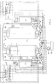
- Fig. 2 shows the application of the invention in the combination of a heat pump 13 with a memory 1 for the production of hot water and a memory 1 'for heating water production, the elements associated with the memory 1' having the same reference numerals as for the memory 1, but with an apostrophe (') are provided.
- a further contact 20c is provided in the relay of the control device 17, which interrupts the circuit for starting the charge pump 10 ', so that the coil 18 of the relay is excited, so that the circuit for hot water generation is operated primarily.
- the function of this arrangement is otherwise the same as that of the previous exemplary embodiment, so that its description is unnecessary.
- the bridging is effected (Bypass) of the first throttle valve 11, 11 'in the secondary circuit through the solenoid valve 21, 21' or the combination of the solenoid valve 21, 21 'with the second throttle valve 22, 22' an increase in the flow rate of the water through the heat exchanger 9, 9 ', so that an increased supply of heat from the heat pump causes the thermostats T4 or T4 'to be switched on and can advantageously be used to fill the storage more quickly.
- the actuator for controlling the flow rate can also be designed according to the invention as a continuously adjustable valve which, for. B. is adjustable by an actuator and also depending on the water temperature at the exit point of the secondary circuit from the heat exchanger, the z. B. measured by means of a thermocouple, the temperature corresponding voltage (actual value) is amplified and compared with a selectable setpoint, the differential voltage between the setpoint and actual value is supplied to the servomotor via a power amplifier.
- a control loop may act ie as an actuator and the drive motor for the charge pump 10 can be regulated 10 ', wherein the flow rate is adapted to the respective heat supply by changing the rotation number in response to the above D i t-ference voltage.
- the drive motor is connected to the output of the power amplifier.
Landscapes
- Engineering & Computer Science (AREA)
- Physics & Mathematics (AREA)
- Thermal Sciences (AREA)
- Chemical & Material Sciences (AREA)
- Combustion & Propulsion (AREA)
- Mechanical Engineering (AREA)
- General Engineering & Computer Science (AREA)
- Heat-Pump Type And Storage Water Heaters (AREA)
- Other Air-Conditioning Systems (AREA)
Claims (8)
Applications Claiming Priority (4)
| Application Number | Priority Date | Filing Date | Title |
|---|---|---|---|
| AT1951/80 | 1980-04-10 | ||
| AT0195180A AT368621B (de) | 1980-04-10 | 1980-04-10 | Temperaturregeleinrichtung des wassers in einem wasserspeicherbehaelter |
| AT0353780A AT372179B (de) | 1980-07-07 | 1980-07-07 | Temperaturregeleinrichtung des wassers in einem wasserspeicherbehaelter |
| AT3537/80 | 1980-07-07 |
Publications (3)
| Publication Number | Publication Date |
|---|---|
| EP0038318A1 EP0038318A1 (fr) | 1981-10-21 |
| EP0038318B1 EP0038318B1 (fr) | 1985-03-20 |
| EP0038318B2 true EP0038318B2 (fr) | 1990-01-17 |
Family
ID=25597256
Family Applications (1)
| Application Number | Title | Priority Date | Filing Date |
|---|---|---|---|
| EP81890059A Expired - Lifetime EP0038318B2 (fr) | 1980-04-10 | 1981-04-06 | Dispositif de réglage pour le réglage du chauffage d'eau sanitaire pour un ballon de stockage |
Country Status (4)
| Country | Link |
|---|---|
| EP (1) | EP0038318B2 (fr) |
| CA (1) | CA1175026A (fr) |
| DE (1) | DE3169328D1 (fr) |
| ES (1) | ES501206A0 (fr) |
Cited By (1)
| Publication number | Priority date | Publication date | Assignee | Title |
|---|---|---|---|---|
| CN105890168A (zh) * | 2016-06-15 | 2016-08-24 | 何玮 | 一种直热式热泵热水器机组 |
Families Citing this family (12)
| Publication number | Priority date | Publication date | Assignee | Title |
|---|---|---|---|---|
| FR2521697A1 (fr) * | 1982-02-17 | 1983-08-19 | Cuenod Thermotech Sa | Dispositif de production d'eau chaude mettant en oeuvre au moins une pompe a chaleur |
| EP0092864A3 (fr) * | 1982-04-15 | 1984-01-18 | I.R.E. Industrie Riunite Eurodomestici S.p.A. | Système de pompe à chaleur pour la production d'eau chaude |
| EP0098788B1 (fr) * | 1982-07-02 | 1988-08-10 | Carrier Corporation | Combinaison d'un circuit de réfrigération et d'un préchauffeur d'eau chaude, système de conditionnement d'air utilisant un tel système et partie d'un tel système avec une telle combinaison |
| DE3311127C2 (de) * | 1983-03-26 | 1994-02-24 | Fa. Rud. Otto Meyer, 2000 Hamburg | Verfahren zur Regelung von im Verbund geschalteten, mit einem Pufferspeicher verbundenen Wärmeerzeugern und Anordnung zur Durchführung des Verfahrens |
| DE3608868A1 (de) * | 1986-03-17 | 1987-09-24 | Stiebel Eltron Gmbh & Co Kg | Aufladesteuerung eines waermepumpenbeheizten warmwasserspeichers |
| SE464667B (sv) * | 1988-08-22 | 1991-05-27 | Thermia Ab | Vaermepumpanlaeggning foer uppvaermning eller kylning av utrymmen samt uppvaermning av tappvarmvatten |
| AT400894B (de) * | 1992-12-17 | 1996-04-25 | Austria Email Waermetech Gmbh | Warmwasserbereitungsanlage |
| IT1289199B1 (it) * | 1996-02-19 | 1998-09-29 | Vaillant Gmbh | Disposizione di accumulatore a strati |
| DE19904937A1 (de) * | 1999-02-06 | 2000-08-10 | Univ Dresden Tech | Verfahren und Anordnung zur Regelung der Warmwassertemperatur in Heizungsanlagen |
| ES2212862B2 (es) * | 2000-12-28 | 2005-06-16 | Jose Garcia Perez | Medios de produccion instantanea de a.c.s. con estabilidad termica a la salida del intercambiador y para eliminacion de la contaminacion por agentes biologicos. |
| CN105569119A (zh) * | 2016-01-10 | 2016-05-11 | 茹朝贵 | 一种新型热水器 |
| WO2018071947A1 (fr) * | 2016-10-20 | 2018-04-26 | Herz Armaturen Ges.M.B.H. | Dispositif pour réguler la température d'eau sanitaire |
Family Cites Families (6)
| Publication number | Priority date | Publication date | Assignee | Title |
|---|---|---|---|---|
| DE1019792B (de) * | 1953-11-27 | 1957-11-21 | Bbc Brown Boveri & Cie | Waermepumpenanlage mit Heisswasser-Druckspeicher |
| NO131902C (fr) * | 1974-03-01 | 1975-08-20 | Ctc Ab | |
| DE2432893A1 (de) * | 1974-07-09 | 1976-01-29 | Robert Lamb | Verfahren zum betrieb einer waermepumpenanlage und anlage zur durchfuehrung des verfahrens |
| US4142379A (en) * | 1976-08-16 | 1979-03-06 | Kuklinski Henry W | Waste energy recovery system |
| US4141222A (en) * | 1977-04-27 | 1979-02-27 | Weatherking, Inc. | Energy recovery system for refrigeration systems |
| FR2443029A1 (fr) * | 1978-06-23 | 1980-06-27 | Technip Cie | Procede et installation de chauffage d'eau utilisant un capteur solaire |
-
1981
- 1981-04-06 EP EP81890059A patent/EP0038318B2/fr not_active Expired - Lifetime
- 1981-04-06 DE DE8181890059T patent/DE3169328D1/de not_active Expired
- 1981-04-07 CA CA000374897A patent/CA1175026A/fr not_active Expired
- 1981-04-09 ES ES501206A patent/ES501206A0/es active Granted
Cited By (1)
| Publication number | Priority date | Publication date | Assignee | Title |
|---|---|---|---|---|
| CN105890168A (zh) * | 2016-06-15 | 2016-08-24 | 何玮 | 一种直热式热泵热水器机组 |
Also Published As
| Publication number | Publication date |
|---|---|
| ES8204135A1 (es) | 1982-04-01 |
| ES501206A0 (es) | 1982-04-01 |
| DE3169328D1 (en) | 1985-04-25 |
| CA1175026A (fr) | 1984-09-25 |
| EP0038318A1 (fr) | 1981-10-21 |
| EP0038318B1 (fr) | 1985-03-20 |
Similar Documents
| Publication | Publication Date | Title |
|---|---|---|
| EP0038318B2 (fr) | Dispositif de réglage pour le réglage du chauffage d'eau sanitaire pour un ballon de stockage | |
| DE2445905B2 (de) | Warmwasserversorgungsanlage mit thermostatisch geregelter Mischbatterie | |
| DE3235364A1 (de) | Warmwasser-heizungsanlage | |
| EP0807790B1 (fr) | Méthode et système pour préparer de l'eau chaude sanitaire | |
| DE4421137A1 (de) | Wasserheizer | |
| DE3917068C2 (fr) | ||
| DE19504730C1 (de) | Warmwasserbereitungsanlage nach dem Durchflußprinzip mit Leistungsbegrenzung | |
| DE1299393B (de) | Warmwassererzeuger, insbesondere Heizwassererzeuger | |
| DE1903774A1 (de) | Vorrichtung zum Erhitzen fluessiger Medien | |
| AT368621B (de) | Temperaturregeleinrichtung des wassers in einem wasserspeicherbehaelter | |
| DE19617111A1 (de) | Wasserheizanlage | |
| DE2750098C2 (de) | Warmwasser-Heizungsanlage | |
| CH692217A5 (de) | Verfahren zur Steuerung einer Wasserheizanlage | |
| DE102007048728A1 (de) | Heizkessel mit Funktion "Solare Heizungsunterstützung" | |
| DE102013012724A1 (de) | Vorrichtung zur Erwärmung von Heizwasser für eine Warmwasserbereitung | |
| DE3310852A1 (de) | Umlaufwasserheizer | |
| AT373376B (de) | Vorrichtung in verbindung mit einer temperaturregeleinrichtung des wassers in einem wasserspeicherbehaelter | |
| CH655376A5 (de) | Heizanlage zur warmwasserbereitung. | |
| AT414272B (de) | Schichtenspeicher | |
| AT407095B (de) | Warmwasserspeicher | |
| CH670497A5 (fr) | ||
| AT397144B (de) | Steuerung und steuerungsanlage zur erwärmung von brauchwasser | |
| DE19706506B4 (de) | Schichtenspeicheranordnung | |
| DE102011014907B4 (de) | Verfahren zur Regelung eines Solarkreislaufs | |
| EP2339247A2 (fr) | Procédé de chauffage d'eau non potable |
Legal Events
| Date | Code | Title | Description |
|---|---|---|---|
| PUAI | Public reference made under article 153(3) epc to a published international application that has entered the european phase |
Free format text: ORIGINAL CODE: 0009012 |
|
| AK | Designated contracting states |
Designated state(s): BE CH DE FR GB IT LI LU NL SE |
|
| 17P | Request for examination filed |
Effective date: 19820226 |
|
| RAP1 | Party data changed (applicant data changed or rights of an application transferred) |
Owner name: AUSTRIA EMAIL-EHT AKTIENGESELLSCHAFT |
|
| ITF | It: translation for a ep patent filed | ||
| GRAA | (expected) grant |
Free format text: ORIGINAL CODE: 0009210 |
|
| AK | Designated contracting states |
Designated state(s): BE CH DE FR GB IT LI LU NL SE |
|
| PG25 | Lapsed in a contracting state [announced via postgrant information from national office to epo] |
Ref country code: NL Effective date: 19850320 Ref country code: FR Free format text: THE PATENT HAS BEEN ANNULLED BY A DECISION OF A NATIONAL AUTHORITY Effective date: 19850320 Ref country code: BE Effective date: 19850320 |
|
| PG25 | Lapsed in a contracting state [announced via postgrant information from national office to epo] |
Ref country code: SE Effective date: 19850407 |
|
| REF | Corresponds to: |
Ref document number: 3169328 Country of ref document: DE Date of ref document: 19850425 |
|
| PG25 | Lapsed in a contracting state [announced via postgrant information from national office to epo] |
Ref country code: LU Free format text: LAPSE BECAUSE OF NON-PAYMENT OF DUE FEES Effective date: 19850430 |
|
| NLV1 | Nl: lapsed or annulled due to failure to fulfill the requirements of art. 29p and 29m of the patents act | ||
| EN | Fr: translation not filed | ||
| PLBI | Opposition filed |
Free format text: ORIGINAL CODE: 0009260 |
|
| PLBI | Opposition filed |
Free format text: ORIGINAL CODE: 0009260 |
|
| GBPC | Gb: european patent ceased through non-payment of renewal fee | ||
| PLAB | Opposition data, opponent's data or that of the opponent's representative modified |
Free format text: ORIGINAL CODE: 0009299OPPO |
|
| PLBI | Opposition filed |
Free format text: ORIGINAL CODE: 0009260 |
|
| 26 | Opposition filed |
Opponent name: STIEBEL ELTRON GMBH & CO.KG Effective date: 19851113 |
|
| 26 | Opposition filed |
Opponent name: EUROHEAT AB Effective date: 19851220 |
|
| 26 | Opposition filed |
Opponent name: NOVA APPARATE GMBH Effective date: 19851219 |
|
| R26 | Opposition filed (corrected) |
Opponent name: STIEBEL ELTRON GMBH & CO.KG * 851220 EUROHEAT AB Effective date: 19851113 |
|
| PG25 | Lapsed in a contracting state [announced via postgrant information from national office to epo] |
Ref country code: GB Effective date: 19881118 |
|
| PUAH | Patent maintained in amended form |
Free format text: ORIGINAL CODE: 0009272 |
|
| STAA | Information on the status of an ep patent application or granted ep patent |
Free format text: STATUS: PATENT MAINTAINED AS AMENDED |
|
| 27A | Patent maintained in amended form |
Effective date: 19900117 |
|
| AK | Designated contracting states |
Kind code of ref document: B2 Designated state(s): BE CH DE FR GB IT LI LU NL SE |
|
| EN3 | Fr: translation not filed ** decision concerning opposition | ||
| PGFP | Annual fee paid to national office [announced via postgrant information from national office to epo] |
Ref country code: CH Payment date: 19910726 Year of fee payment: 11 |
|
| PG25 | Lapsed in a contracting state [announced via postgrant information from national office to epo] |
Ref country code: LI Effective date: 19920430 Ref country code: CH Effective date: 19920430 |
|
| REG | Reference to a national code |
Ref country code: CH Ref legal event code: PL |
|
| EUG | Se: european patent has lapsed |
Ref document number: 81890059.9 Effective date: 19860702 |
|
| PGFP | Annual fee paid to national office [announced via postgrant information from national office to epo] |
Ref country code: DE Payment date: 19980319 Year of fee payment: 18 |
|
| PG25 | Lapsed in a contracting state [announced via postgrant information from national office to epo] |
Ref country code: DE Free format text: LAPSE BECAUSE OF NON-PAYMENT OF DUE FEES Effective date: 20000201 |
|
| APAH | Appeal reference modified |
Free format text: ORIGINAL CODE: EPIDOSCREFNO |