EP0037770B1 - Système de transmission de données numériques par paquets utilisant un type particulier de mots de synchronisation - Google Patents
Système de transmission de données numériques par paquets utilisant un type particulier de mots de synchronisation Download PDFInfo
- Publication number
- EP0037770B1 EP0037770B1 EP81400490A EP81400490A EP0037770B1 EP 0037770 B1 EP0037770 B1 EP 0037770B1 EP 81400490 A EP81400490 A EP 81400490A EP 81400490 A EP81400490 A EP 81400490A EP 0037770 B1 EP0037770 B1 EP 0037770B1
- Authority
- EP
- European Patent Office
- Prior art keywords
- word
- binary elements
- unique
- transmission system
- words
- Prior art date
- Legal status (The legal status is an assumption and is not a legal conclusion. Google has not performed a legal analysis and makes no representation as to the accuracy of the status listed.)
- Expired
Links
Images


Classifications
-
- H—ELECTRICITY
- H04—ELECTRIC COMMUNICATION TECHNIQUE
- H04B—TRANSMISSION
- H04B7/00—Radio transmission systems, i.e. using radiation field
- H04B7/14—Relay systems
- H04B7/15—Active relay systems
- H04B7/204—Multiple access
- H04B7/212—Time-division multiple access [TDMA]
- H04B7/2125—Synchronisation
-
- H—ELECTRICITY
- H04—ELECTRIC COMMUNICATION TECHNIQUE
- H04L—TRANSMISSION OF DIGITAL INFORMATION, e.g. TELEGRAPHIC COMMUNICATION
- H04L7/00—Arrangements for synchronising receiver with transmitter
- H04L7/04—Speed or phase control by synchronisation signals
- H04L7/041—Speed or phase control by synchronisation signals using special codes as synchronising signal
- H04L7/046—Speed or phase control by synchronisation signals using special codes as synchronising signal using a dotting sequence
Definitions
- the present invention relates to a digital packet data transmission system. It finds an application in telecommunications.
- TDMA time division multiple access
- TDMA time division multiple access
- a receiving earth station must, to correctly collect the transmitted data, reconstruct different cadences used in the transmitting station: carrier frequency, digital rhythm and identify the start of the packet.
- each packet is preceded by a preamble consisting of a rhythm recovery sequence followed by a combination chosen to facilitate tracking of the start of the packet. This combination is called a “single word”.
- the invention relates more particularly to such words and to the means of using them.
- FIG. 1 The format of a TDMA type link is illustrated in FIG. 1.
- the data are inserted in a multiframe system comprising, for example, sixteen frames numbered from 0 to 15.
- the duration of each multiframe depends on the systems: it is by example of 2 ms for the INTELSAT system.
- Frame 0 contains reference packets indicating the start of the multiframe and the following frames of data packets.
- the structure of these packages is illustrated schematically in Figure 2.
- a packet includes a preamble, which is followed by data if it is a data packet.
- the preamble firstly includes a series of binary elements constituting a rhythm recovery sequence (SRR) (in English terminology: “carrier and bits timing recovery sequence”).
- SRR rhythm recovery sequence
- this sequence consists of a series of "0” and “1", a "1” indicating a phase jump of 180 ° and a "0 the absence of such a jump.
- MU synchronization word
- a particular unique word is used in the data packets: it is the unique word of data (MU o ).
- MU ref unique reference words
- the preamble ends with a service and signaling channel (VSS).
- a single word detector is generally constituted by a circuit such as that of FIG. 3. It includes a shift register 10 formed of flip-flops 11, 12, 13 ... with one input and two complementary outputs Q and Q. L ' one or other of these outputs is connected to an adder 20. The set of outputs thus connected corresponds to the complement of the single word to be detected. So, if this word is for example 10110 ... the outputs of the flip-flops which are connected to the adder are the Q output for the first, the Q output for the second, the Q output for the third, the Q output for the fourth, output Q for the fifth, etc.
- the digital signals among which the single word in question is sought are introduced into the shift register 10. They progress there at each pulse of a control clock H.
- Such a circuit therefore delivers a signal which represents the difference between the word sought and the word received.
- This difference is called “Hamming distance”: it is very exactly the number of binary elements of the same rank that differ in two words, or the weight, modulo 2 n, of the sum of two words of n binary elements.
- the document FR-A-1 585 273 describes a system in which two different codes are nested, chosen so that their autocorrelation functions present a zero sum for all the values of time. different from a multiple of the number of bits in the code. In such a system, it is therefore necessary to use, in the reception means, two different circuits adapted to the two different nested words.
- the present invention aims to solve all these difficulties. To this end, it proposes the use of a unique word of 2 n binary elements which consists of two unique words of n interlaced and offset binary elements.
- the single word detector used is capable of processing words of n binary elements and it alternately receives the series of binary elements of odd and even rank of the word of 2 n binary elements.
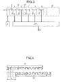
- FIG. 4 represents the structure of a single word of 2 n binary elements in accordance with the invention.
- Such a word is composed of a word M of the form: interlaced with the complementary word M of the form: each of the letters indicating a binary element equal to 0 or 1.
- the offset between the two words can be arbitrary and equal to a number p of periods T of the binary signal.
- the sequence is started in such a way that the first binary elements extend the rhythm recovery sequence.
- the complementary word is then:
- the single word detector determines the distance d from the expected code (M) to the code received alternately on the even and odd bits, followed by the data (X), namely respectively:
- the distance d from the expected single word M to the single word sent and shifted by n elements is given in FIG. 5 where the offset, plotted on the abscissa, is expressed in periods T.
- the probability P 3 of false detection in noise is:
- the unique word detector decides that the local unique word is found without error if successively: according to figure 5.
- the single word of the local station and those of the remote stations are sought in windows of a few binary elements around the nominal positions.
- the single word detector decides that the single word of an ordinary station is found with at most 4 errors among 16 binary elements if d ⁇ 4.
- the single word detector determines the distance d of the expected code (M): to the code received alternately on the even and odd elements, followed by the data (X): and
- the performance of the single reference word is different depending on whether the TDMA terminal is in synchronized mode or not:
- the probability P 3 of false detection in noise is:
- the unique word detector decides that the unique reference word is found without error if successively: according to figure 6.
- the single word of the reference station is sought in a window of a few binary elements around the nominal position.
- a second single reference word (MU ref2 ) can be obtained by shifting the word M by 3 periods with respect to M.
- the Hamming distance d then varies as shown in FIG. 7.
- this word will be considered as found with four errors (or less) if d ⁇ 12.
- a third unique reference word MU ref3 can be obtained by shifting the word M of five periods with respect to M.
- the Hamming distance d then varies as shown in FIG. 8.
- the means for implementing these words of the invention are shown in FIG. 9.
- the circuit shown comprises a double shift register 31, 32 receiving the trains of binary elements of odd (P) and even (Q) rank. , a circuit 33 for calculating the Hamming distance of a circuit 34 formed by comparators 35, 36, 37, 38 respectively at 0, 4, 12 and 16, a circuit 40 formed by cells with delay of 1 period (T) 41 and 42, 2-period delay cells (2T) 43 and 44 and ET type logic gates 51, 52, 53 and 54.
- the operation of this circuit is as follows.
- the digital signal divided according to known means into a train P of odd elements and a train Q of even elements, enters the double shift register 31-32 so that the circuit 34 sees alternately the even and odd sequences which were specified above.
- the Hamming distance d begins to oscillate between the values 7 and 9 as indicated in the diagrams of FIGS. 5 to 8. Then, when the word M fills one or the other of the half registers 31 or 32, the distance d suddenly drops to 0, then goes up to value 16 when the word M fills the other half-register.
- the circuit 34 delivers signals indicating the instants of appearance of these events.
- the output of gate 53 signals the detection of MU rer2 and that of 54 the detection of MU ref3 , still in search mode.
- the detections in synchronized mode they are signaled on the comparator output connections at 4 (for MU o ) and at 12 for MUret 1, 2, 3.
- the implementation of the single word in accordance with the invention presents another which is that of enabling ambiguity to be resolved in the case of a four-state phase modulation (MDP4).
- MDP4 phase modulation
Landscapes
- Engineering & Computer Science (AREA)
- Computer Networks & Wireless Communication (AREA)
- Signal Processing (AREA)
- Synchronisation In Digital Transmission Systems (AREA)
- Time-Division Multiplex Systems (AREA)
- Data Exchanges In Wide-Area Networks (AREA)
- Small-Scale Networks (AREA)
- Mobile Radio Communication Systems (AREA)
- Radio Relay Systems (AREA)
Applications Claiming Priority (2)
| Application Number | Priority Date | Filing Date | Title |
|---|---|---|---|
| FR8007561A FR2480049B1 (fr) | 1980-04-03 | 1980-04-03 | Systeme de transmission de donnees numeriques par paquets de synchronisation |
| FR8007561 | 1980-04-03 |
Publications (2)
| Publication Number | Publication Date |
|---|---|
| EP0037770A1 EP0037770A1 (fr) | 1981-10-14 |
| EP0037770B1 true EP0037770B1 (fr) | 1984-06-13 |
Family
ID=9240512
Family Applications (1)
| Application Number | Title | Priority Date | Filing Date |
|---|---|---|---|
| EP81400490A Expired EP0037770B1 (fr) | 1980-04-03 | 1981-03-27 | Système de transmission de données numériques par paquets utilisant un type particulier de mots de synchronisation |
Country Status (6)
| Country | Link |
|---|---|
| US (1) | US4414662A (enExample) |
| EP (1) | EP0037770B1 (enExample) |
| JP (1) | JPS56154848A (enExample) |
| CA (1) | CA1164589A (enExample) |
| DE (1) | DE3164103D1 (enExample) |
| FR (1) | FR2480049B1 (enExample) |
Families Citing this family (8)
| Publication number | Priority date | Publication date | Assignee | Title |
|---|---|---|---|---|
| US4688218A (en) * | 1981-07-15 | 1987-08-18 | Etablissement Public De Diffusion Dit "Telediffusion De France" | Multiplex channels for continuous flow for numerical signal |
| GB8310315D0 (en) * | 1983-04-15 | 1983-05-18 | British Broadcasting Corp | Multiplexed digital data transmission |
| GB2139050B (en) * | 1983-04-15 | 1986-10-01 | British Broadcasting Corp | Digital data transmission |
| US4744081A (en) * | 1987-05-18 | 1988-05-10 | Northern Telecom Limited | Frame find circuit and method |
| US5255291A (en) * | 1988-11-14 | 1993-10-19 | Stratacom, Inc. | Microprocessor based packet isochronous clocking transmission system and method |
| CA1312656C (en) * | 1989-08-24 | 1993-01-12 | Steven Messenger | Wireless communications systems |
| JPH04262630A (ja) * | 1991-02-15 | 1992-09-18 | Fujitsu Ltd | 衛星通信方式 |
| JP3766993B2 (ja) * | 1995-10-30 | 2006-04-19 | ソニー株式会社 | 同期信号検出回路 |
Family Cites Families (3)
| Publication number | Priority date | Publication date | Assignee | Title |
|---|---|---|---|---|
| US3335409A (en) * | 1964-06-25 | 1967-08-08 | Westinghouse Electric Corp | Permutation apparatus |
| US3519746A (en) * | 1967-06-13 | 1970-07-07 | Itt | Means and method to obtain an impulse autocorrelation function |
| JPS5040962B1 (enExample) * | 1971-07-20 | 1975-12-27 |
-
1980
- 1980-04-03 FR FR8007561A patent/FR2480049B1/fr not_active Expired
-
1981
- 1981-03-24 US US06/247,170 patent/US4414662A/en not_active Expired - Fee Related
- 1981-03-27 EP EP81400490A patent/EP0037770B1/fr not_active Expired
- 1981-03-27 DE DE8181400490T patent/DE3164103D1/de not_active Expired
- 1981-04-02 JP JP5002881A patent/JPS56154848A/ja active Granted
- 1981-04-02 CA CA000374477A patent/CA1164589A/en not_active Expired
Also Published As
| Publication number | Publication date |
|---|---|
| FR2480049A1 (fr) | 1981-10-09 |
| JPS6362137B2 (enExample) | 1988-12-01 |
| DE3164103D1 (en) | 1984-07-19 |
| US4414662A (en) | 1983-11-08 |
| JPS56154848A (en) | 1981-11-30 |
| FR2480049B1 (fr) | 1987-08-14 |
| CA1164589A (en) | 1984-03-27 |
| EP0037770A1 (fr) | 1981-10-14 |
Similar Documents
| Publication | Publication Date | Title |
|---|---|---|
| FR2733655A1 (fr) | Procede et systeme d'acquisition de cadencement de trames pour des systemes sans fil a acces multiple par repartition dans le temps | |
| FR2803459A1 (fr) | Systeme de transmission a diversite spatiale, temporelle et frequentielle | |
| FR2473824A1 (fr) | Procede de commutation entre les recepteurs et les correlateurs d'un systeme de communication et appareil de reception-correlation pour la mise en oeuvre de ce procede | |
| EP0037770B1 (fr) | Système de transmission de données numériques par paquets utilisant un type particulier de mots de synchronisation | |
| FR2485841A1 (fr) | Procede et dispositif de traitement de signaux numeriques | |
| EP0621703B1 (fr) | Procédé de récupération d'horloge et de synchronisation pour la réception d'informations transmises par un réseau ATM et dispositif de mise en oeuvre du procédé | |
| FR2673298A1 (fr) | Methode et dispositif de transmission sismique a taux d'erreur tres faible. | |
| EP0018242B1 (fr) | Procédé et dispositif de démodulation stochastique pour signaux modulés en sauts de phase, fonctionnant en temps partagé sur plusieurs canaux | |
| EP0330560B1 (fr) | Procédé et dispositif de transmission de données | |
| EP0056748B1 (fr) | Procédé de synchronisation à la réception de signaux numériques transmis par paquets | |
| EP0082054B1 (fr) | Procédé de synchronisation des postes émetteurs-récepteurs d'un réseau à sauts de fréquence, et poste destiné à la mise en oeuvre de ce procédé | |
| EP1081855B1 (fr) | Procédé et dispositif de synchronisation d'un recepteur de communication | |
| FR2764147A1 (fr) | Procede et dispositif de recuperation de synchronisation sur un signal transmis a un recepteur de telephone mobile | |
| EP0148098B1 (fr) | Circuit de régénération de signaux périodiques | |
| FR2855687A1 (fr) | Dispositif pour recuperer un signal de synchronisation | |
| EP0994580B1 (fr) | Procédé de transmission dans un système de radiocommunication du type à accès multiple | |
| EP0982866B1 (fr) | Procédé de codage convolutif et de transmission par paquets d'un flux série de données numériques, procédé et dispositif de décodage correspondants | |
| EP0363231B1 (fr) | Procédé de transmission d'information sur une liaison bidirectionelle et dispositif de mise en oeuvre de ce procédé | |
| EP0399023B1 (fr) | Dispositif de synchronisation pour une suite de trames a longueur variable | |
| EP1897264A2 (fr) | Procede et dispositif de synchronisation trame | |
| EP3963757B1 (fr) | Procédé et dispositif récepteur pour détecter le début d'une trame d'un signal de communications par satellite | |
| EP1400028B1 (fr) | Module discriminateur de trajets multiples pour un systeme de navigation. | |
| WO2005124383A1 (fr) | Procede de transmission d'un signal de radionavigation | |
| FR2673497A1 (fr) | Procede pour realiser une transmission protegee de signaux radioelectriques. | |
| FR2633470A1 (fr) | Procede de demodulation et demodulateur de signaux numeriques d'amplitude d'enveloppe constante modules en phase et/ou en frequence de facon continue |
Legal Events
| Date | Code | Title | Description |
|---|---|---|---|
| PUAI | Public reference made under article 153(3) epc to a published international application that has entered the european phase |
Free format text: ORIGINAL CODE: 0009012 |
|
| AK | Designated contracting states |
Designated state(s): BE DE GB IT NL SE |
|
| 17P | Request for examination filed |
Effective date: 19820322 |
|
| ITF | It: translation for a ep patent filed | ||
| GRAA | (expected) grant |
Free format text: ORIGINAL CODE: 0009210 |
|
| AK | Designated contracting states |
Designated state(s): BE DE GB IT NL SE |
|
| REF | Corresponds to: |
Ref document number: 3164103 Country of ref document: DE Date of ref document: 19840719 |
|
| PLBE | No opposition filed within time limit |
Free format text: ORIGINAL CODE: 0009261 |
|
| STAA | Information on the status of an ep patent application or granted ep patent |
Free format text: STATUS: NO OPPOSITION FILED WITHIN TIME LIMIT |
|
| 26N | No opposition filed | ||
| PGFP | Annual fee paid to national office [announced via postgrant information from national office to epo] |
Ref country code: BE Payment date: 19920219 Year of fee payment: 12 |
|
| PGFP | Annual fee paid to national office [announced via postgrant information from national office to epo] |
Ref country code: SE Payment date: 19920221 Year of fee payment: 12 |
|
| PGFP | Annual fee paid to national office [announced via postgrant information from national office to epo] |
Ref country code: GB Payment date: 19920324 Year of fee payment: 12 |
|
| ITTA | It: last paid annual fee | ||
| PGFP | Annual fee paid to national office [announced via postgrant information from national office to epo] |
Ref country code: NL Payment date: 19920331 Year of fee payment: 12 |
|
| PGFP | Annual fee paid to national office [announced via postgrant information from national office to epo] |
Ref country code: DE Payment date: 19930224 Year of fee payment: 13 |
|
| PG25 | Lapsed in a contracting state [announced via postgrant information from national office to epo] |
Ref country code: GB Effective date: 19930327 |
|
| PG25 | Lapsed in a contracting state [announced via postgrant information from national office to epo] |
Ref country code: SE Effective date: 19930328 |
|
| PG25 | Lapsed in a contracting state [announced via postgrant information from national office to epo] |
Ref country code: BE Effective date: 19930331 |
|
| BERE | Be: lapsed |
Owner name: BOUSQUET JEAN-CLAUDE Effective date: 19930331 |
|
| PG25 | Lapsed in a contracting state [announced via postgrant information from national office to epo] |
Ref country code: NL Effective date: 19931001 |
|
| NLV4 | Nl: lapsed or anulled due to non-payment of the annual fee | ||
| GBPC | Gb: european patent ceased through non-payment of renewal fee |
Effective date: 19930327 |
|
| PG25 | Lapsed in a contracting state [announced via postgrant information from national office to epo] |
Ref country code: DE Effective date: 19941201 |
|
| EUG | Se: european patent has lapsed |
Ref document number: 81400490.9 Effective date: 19931008 |