EP0037770B1 - Transmission system for digital data packets using a particular type of synchronization words - Google Patents
Transmission system for digital data packets using a particular type of synchronization words Download PDFInfo
- Publication number
- EP0037770B1 EP0037770B1 EP81400490A EP81400490A EP0037770B1 EP 0037770 B1 EP0037770 B1 EP 0037770B1 EP 81400490 A EP81400490 A EP 81400490A EP 81400490 A EP81400490 A EP 81400490A EP 0037770 B1 EP0037770 B1 EP 0037770B1
- Authority
- EP
- European Patent Office
- Prior art keywords
- word
- binary elements
- unique
- transmission system
- words
- Prior art date
- Legal status (The legal status is an assumption and is not a legal conclusion. Google has not performed a legal analysis and makes no representation as to the accuracy of the status listed.)
- Expired
Links
Images


Classifications
-
- H—ELECTRICITY
- H04—ELECTRIC COMMUNICATION TECHNIQUE
- H04B—TRANSMISSION
- H04B7/00—Radio transmission systems, i.e. using radiation field
- H04B7/14—Relay systems
- H04B7/15—Active relay systems
- H04B7/204—Multiple access
- H04B7/212—Time-division multiple access [TDMA]
- H04B7/2125—Synchronisation
-
- H—ELECTRICITY
- H04—ELECTRIC COMMUNICATION TECHNIQUE
- H04L—TRANSMISSION OF DIGITAL INFORMATION, e.g. TELEGRAPHIC COMMUNICATION
- H04L7/00—Arrangements for synchronising receiver with transmitter
- H04L7/04—Speed or phase control by synchronisation signals
- H04L7/041—Speed or phase control by synchronisation signals using special codes as synchronising signal
- H04L7/046—Speed or phase control by synchronisation signals using special codes as synchronising signal using a dotting sequence
Definitions
- the present invention relates to a digital packet data transmission system. It finds an application in telecommunications.
- TDMA time division multiple access
- TDMA time division multiple access
- a receiving earth station must, to correctly collect the transmitted data, reconstruct different cadences used in the transmitting station: carrier frequency, digital rhythm and identify the start of the packet.
- each packet is preceded by a preamble consisting of a rhythm recovery sequence followed by a combination chosen to facilitate tracking of the start of the packet. This combination is called a “single word”.
- the invention relates more particularly to such words and to the means of using them.
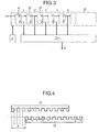
- FIG. 1 The format of a TDMA type link is illustrated in FIG. 1.
- the data are inserted in a multiframe system comprising, for example, sixteen frames numbered from 0 to 15.
- the duration of each multiframe depends on the systems: it is by example of 2 ms for the INTELSAT system.
- Frame 0 contains reference packets indicating the start of the multiframe and the following frames of data packets.
- the structure of these packages is illustrated schematically in Figure 2.
- a packet includes a preamble, which is followed by data if it is a data packet.
- the preamble firstly includes a series of binary elements constituting a rhythm recovery sequence (SRR) (in English terminology: “carrier and bits timing recovery sequence”).
- SRR rhythm recovery sequence
- this sequence consists of a series of "0” and “1", a "1” indicating a phase jump of 180 ° and a "0 the absence of such a jump.
- MU synchronization word
- a particular unique word is used in the data packets: it is the unique word of data (MU o ).
- MU ref unique reference words
- the preamble ends with a service and signaling channel (VSS).
- a single word detector is generally constituted by a circuit such as that of FIG. 3. It includes a shift register 10 formed of flip-flops 11, 12, 13 ... with one input and two complementary outputs Q and Q. L ' one or other of these outputs is connected to an adder 20. The set of outputs thus connected corresponds to the complement of the single word to be detected. So, if this word is for example 10110 ... the outputs of the flip-flops which are connected to the adder are the Q output for the first, the Q output for the second, the Q output for the third, the Q output for the fourth, output Q for the fifth, etc.
- the digital signals among which the single word in question is sought are introduced into the shift register 10. They progress there at each pulse of a control clock H.
- Such a circuit therefore delivers a signal which represents the difference between the word sought and the word received.
- This difference is called “Hamming distance”: it is very exactly the number of binary elements of the same rank that differ in two words, or the weight, modulo 2 n, of the sum of two words of n binary elements.
- the document FR-A-1 585 273 describes a system in which two different codes are nested, chosen so that their autocorrelation functions present a zero sum for all the values of time. different from a multiple of the number of bits in the code. In such a system, it is therefore necessary to use, in the reception means, two different circuits adapted to the two different nested words.
- the present invention aims to solve all these difficulties. To this end, it proposes the use of a unique word of 2 n binary elements which consists of two unique words of n interlaced and offset binary elements.
- the single word detector used is capable of processing words of n binary elements and it alternately receives the series of binary elements of odd and even rank of the word of 2 n binary elements.
- FIG. 4 represents the structure of a single word of 2 n binary elements in accordance with the invention.
- Such a word is composed of a word M of the form: interlaced with the complementary word M of the form: each of the letters indicating a binary element equal to 0 or 1.
- the offset between the two words can be arbitrary and equal to a number p of periods T of the binary signal.
- the sequence is started in such a way that the first binary elements extend the rhythm recovery sequence.
- the complementary word is then:
- the single word detector determines the distance d from the expected code (M) to the code received alternately on the even and odd bits, followed by the data (X), namely respectively:
- the distance d from the expected single word M to the single word sent and shifted by n elements is given in FIG. 5 where the offset, plotted on the abscissa, is expressed in periods T.
- the probability P 3 of false detection in noise is:
- the unique word detector decides that the local unique word is found without error if successively: according to figure 5.
- the single word of the local station and those of the remote stations are sought in windows of a few binary elements around the nominal positions.
- the single word detector decides that the single word of an ordinary station is found with at most 4 errors among 16 binary elements if d ⁇ 4.
- the single word detector determines the distance d of the expected code (M): to the code received alternately on the even and odd elements, followed by the data (X): and
- the performance of the single reference word is different depending on whether the TDMA terminal is in synchronized mode or not:
- the probability P 3 of false detection in noise is:
- the unique word detector decides that the unique reference word is found without error if successively: according to figure 6.
- the single word of the reference station is sought in a window of a few binary elements around the nominal position.
- a second single reference word (MU ref2 ) can be obtained by shifting the word M by 3 periods with respect to M.
- the Hamming distance d then varies as shown in FIG. 7.
- this word will be considered as found with four errors (or less) if d ⁇ 12.
- a third unique reference word MU ref3 can be obtained by shifting the word M of five periods with respect to M.
- the Hamming distance d then varies as shown in FIG. 8.
- the means for implementing these words of the invention are shown in FIG. 9.
- the circuit shown comprises a double shift register 31, 32 receiving the trains of binary elements of odd (P) and even (Q) rank. , a circuit 33 for calculating the Hamming distance of a circuit 34 formed by comparators 35, 36, 37, 38 respectively at 0, 4, 12 and 16, a circuit 40 formed by cells with delay of 1 period (T) 41 and 42, 2-period delay cells (2T) 43 and 44 and ET type logic gates 51, 52, 53 and 54.
- the operation of this circuit is as follows.
- the digital signal divided according to known means into a train P of odd elements and a train Q of even elements, enters the double shift register 31-32 so that the circuit 34 sees alternately the even and odd sequences which were specified above.
- the Hamming distance d begins to oscillate between the values 7 and 9 as indicated in the diagrams of FIGS. 5 to 8. Then, when the word M fills one or the other of the half registers 31 or 32, the distance d suddenly drops to 0, then goes up to value 16 when the word M fills the other half-register.
- the circuit 34 delivers signals indicating the instants of appearance of these events.
- the output of gate 53 signals the detection of MU rer2 and that of 54 the detection of MU ref3 , still in search mode.
- the detections in synchronized mode they are signaled on the comparator output connections at 4 (for MU o ) and at 12 for MUret 1, 2, 3.
- the implementation of the single word in accordance with the invention presents another which is that of enabling ambiguity to be resolved in the case of a four-state phase modulation (MDP4).
- MDP4 phase modulation
Description
La présente invention a pour objet un système de transmission de données numériques par paquets. Elle trouve une application en télécommunications.The present invention relates to a digital packet data transmission system. It finds an application in telecommunications.
Dans les systèmes modernes de liaisons par satellites dits en « accès multiple par répartition dans le temps » (en abrégé « AMRT » et, en terminologie anglosaxonne, « TDMA »), les données sont transmises par paquets. Dans de tels systèmes, une station terrienne réceptrice doit, pour recueillir correctement les données transmises, reconstituer différentes cadences utilisées dans la station émettrice : fréquence de l'onde porteuse, rythme numérique et identifier le début du paquet. A cet effet, chaque paquet est précédé d'un préambule constitué d'une séquence de récupération de rythme suivie d'une combinaison choisie pour faciliter le repérage du début du paquet. Cette combinaison est appelée « mot unique ». L'invention porte plus particulièrement sur de tels mots et sur les moyens de les mettre en oeuvre.In modern so-called "time division multiple access" satellite link systems (abbreviated as "TDMA" and, in English terminology, "TDMA"), data is transmitted in packets. In such systems, a receiving earth station must, to correctly collect the transmitted data, reconstruct different cadences used in the transmitting station: carrier frequency, digital rhythm and identify the start of the packet. To this end, each packet is preceded by a preamble consisting of a rhythm recovery sequence followed by a combination chosen to facilitate tracking of the start of the packet. This combination is called a “single word”. The invention relates more particularly to such words and to the means of using them.
Le format d'une liaison de type AMRT est illustré sur la figure 1. Les données sont insérées dans un système de multitrame comportant, par exemple, seize trames numérotées de 0 à 15. La durée de chaque multitrame dépend des systèmes : elle est par exemple de 2 ms pour le système INTELSAT. La trame 0 contient des paquets de référence indiquant le début de la multitrame et les trames suivantes des paquets de données. La structure de ces paquets est illustrée schématiquement sur la figure 2.The format of a TDMA type link is illustrated in FIG. 1. The data are inserted in a multiframe system comprising, for example, sixteen frames numbered from 0 to 15. The duration of each multiframe depends on the systems: it is by example of 2 ms for the INTELSAT system.
Un paquet comprend un préambule, lequel est suivi de données s'il s'agit d'un paquet de données. Le préambule comprend tout d'abord une suite d'éléments binaires constituant une séquence de récupération de rythme (SRR) (en terminologie anglosaxonne : « carrier and bits timing recovery sequence »). En modulation de phase à deux états, cette séquence est constituée par une suite de « 0 » et de « 1 », un « 1 » indiquant un saut de phase de 180° et un « 0 l'absence d'un tel saut.A packet includes a preamble, which is followed by data if it is a data packet. The preamble firstly includes a series of binary elements constituting a rhythm recovery sequence (SRR) (in English terminology: "carrier and bits timing recovery sequence"). In two-state phase modulation, this sequence consists of a series of "0" and "1", a "1" indicating a phase jump of 180 ° and a "0 the absence of such a jump.
Cette séquence de récupération de rythme est suivie d'un mot unique de synchronisation (en abrégé, par la suite : « MU »). Dans une multitrame, un mot unique particulier est utilisé dans les paquets de données : c'est le mot unique de données (MUo). Mais un ou plusieurs mots uniques de référence (MUref) peuvent être employés dans les paquets de référence qui commencent la multitrame. Le préambule se termine par une voie de service et de signalisation (VSS).This rhythm recovery sequence is followed by a single synchronization word (abbreviated thereafter: "MU"). In a multiframe, a particular unique word is used in the data packets: it is the unique word of data (MU o ). But one or more unique reference words (MU ref ) can be used in the reference packets that start the multiframe. The preamble ends with a service and signaling channel (VSS).
Une telle organisation est décrite dans le document « IEE Transactions on Communication Technology », volume COM-16, N° 4, Août 1968, pages 597-605. Ce document décrit, de manière générale, un système de transmission de données numériques par paquets comprenant :
- - des moyens d'émission aptes à former des paquets comprenant un préambule formé notamment d'une séquence d'éléments binaires de récupération de rythme suivie d'une combinaison d'éléments binaires appelée mot unique,
- - des moyens de réception comprenant notamment un décodeur apte à détecter la présence d'un mot unique dans les signaux reçus.
- transmission means able to form packets comprising a preamble formed in particular of a sequence of binary elements of rhythm recovery followed by a combination of binary elements called a single word,
- reception means comprising in particular a decoder capable of detecting the presence of a single word in the signals received.
Dans les spécifications relatives aux systèmes AMRT et notamment dans celles du système INTELSAT, il est prévu quatre mots uniques différents pour distinguer quatre types de paquets. L'application de telles normes nécessite la mise en oeuvre de deux détecteurs de mots uniques. Ce point mérite qu'on s'y arrête si l'on veut bien comprendre la présente invention.In the specifications relating to TDMA systems and in particular those of the INTELSAT system, four different unique words are provided to distinguish four types of packets. The application of such standards requires the implementation of two unique word detectors. This point deserves attention if we want to understand the present invention.
Un détecteur de mot unique est généralement constitué par un circuit tel que celui de la figure 3. Il comprend un registre à décalage 10 formé de bascules 11, 12, 13... à une entrée et deux sorties complémentaires Q et Q. L'une ou l'autre de ces sorties est reliée à un additionneur 20. L'ensemble des sorties ainsi connectées correspond au complément du mot unique à détecter. Ainsi, si ce mot est par exemple 10110... les sorties des bascules qui sont reliées à l'additionneur sont la sortie Q pour la première, la sortie Q pour la seconde, la sortie Q pour la troisième, la sortie Q pour la quatrième, la sortie Q pour la cinquième, etc... Les signaux numériques parmi lesquels on recherche le mot unique en question sont introduits dans le registre à décalage 10. Ils y progressent à chaque impulsion d'une horloge de commande H. Lorsque le mot recherché remplit le registre, toutes les sorties des bascules qui sont reliées à l'additionneur d délivrent à ce dernier un « 0 ». L'additionneur 20 délivre un signal d qui est nul. Toute autre configuration du mot présent dans le registre donne un signal d différent de zéro.A single word detector is generally constituted by a circuit such as that of FIG. 3. It includes a
Un tel circuit délivre donc un signal qui représente l'écart entre le mot recherché et le mot reçu. Cet écart est dit « distance de Hamming » : c'est très exactement le nombre d'éléments binaires de même rang qui diffèrent dans deux mots, ou encore le poids, modulo 2 n, de la somme de deux mots de n éléments binaires.Such a circuit therefore delivers a signal which represents the difference between the word sought and the word received. This difference is called "Hamming distance": it is very exactly the number of binary elements of the same rank that differ in two words, or the weight, modulo 2 n, of the sum of two words of n binary elements.
Ce rappel sur les détecteurs des mots uniques permet de comprendre que l'utilisation de plusieurs mots uniques différents implique l'utilisation de plusieurs détecteurs, puisque le branchement des bascules d'un détecteur est spécifique du mot à détecter. Or, ceci constitue un inconvénient majeur car de tels détecteurs sont onéreux. C'est ainsi par exemple que le document FR-A-1 585 273 décrit un système où l'on imbrique deux codes différents, choisis de telle sorte que leurs fonctions d'autocorréla- tion présentent une somme nulle pour toutes les valeurs du temps différentes d'un multiple du nombre d'éléments binaires du code. Dans un tel système, il est donc nécessaire d'utiliser, dans les moyens de réception, deux circuits différents adaptés aux deux mots différents imbriqués.This reminder on the detectors of unique words makes it possible to understand that the use of several different unique words implies the use of several detectors, since the connection of the flip-flops of a detector is specific to the word to be detected. However, this constitutes a major drawback because such detectors are expensive. Thus, for example, the document FR-A-1 585 273 describes a system in which two different codes are nested, chosen so that their autocorrelation functions present a zero sum for all the values of time. different from a multiple of the number of bits in the code. In such a system, it is therefore necessary to use, in the reception means, two different circuits adapted to the two different nested words.
En plus de cet inconvénient, les systèmes de l'art antérieur en présentent deux autres, liés au fait que, en pratique, des erreurs de localisation du paquet sont possibles. En effet :
- - la démodulation ou le décodage différentiel généralement utilisés ont pour effet de corréler fortement les erreurs sur les éléments binaires de symboles voisins alors que les erreurs sont indépendantes sur des éléments binaires distants de plus d'un symbole ;
- - il est difficile de trouver un mot unique tel que lui-même et son complémentaire précédés chacun d'une même séquence de récupération de rythme possèdent une fonction d'autocorrélation optimale.
- - the demodulation or the differential decoding generally used have the effect of strongly correlating the errors on the binary elements of neighboring symbols while the errors are independent on binary elements distant by more than one symbol;
- - it is difficult to find a single word such as itself and its complement each preceded by the same rhythm recovery sequence have an optimal autocorrelation function.
La présente invention a pour but de résoudre toutes ces difficultés. A cette fin, elle propose l'utilisation d'un mot unique de 2 n éléments binaires qui est constitué par deux mots uniques de n éléments binaires entrelacés et décalés. Le détecteur de mot unique utilisé est apte à traiter des mots de n éléments binaires et il reçoit alternativement la suite des éléments binaires de rang impair et pair du mot de 2 n éléments binaires.The present invention aims to solve all these difficulties. To this end, it proposes the use of a unique word of 2 n binary elements which consists of two unique words of n interlaced and offset binary elements. The single word detector used is capable of processing words of n binary elements and it alternately receives the series of binary elements of odd and even rank of the word of 2 n binary elements.
De cette manière, l'invention procure, sur les systèmes de l'art antérieur, les avantages suivants :
- - un seul détecteur de mot unique permet la détection de plusieurs mots uniques différents (selon le décalage des mots élémentaires qui les composent),
- - un détecteur de mot unique de n éléments binaires permet la détection d'un mot unique de 2 n éléments binaires,
- - la fonction d'intercorrélation du mot unique au préambule est améliorée parce que le détecteur de mot unique exploite un symbole sur deux,
- - chaque mot unique de n éléments binaires est construit sur les symboles de rang de même parité de sorte que les erreurs sur les éléments binaires sont indépendantes.
- - a single unique word detector allows the detection of several different unique words (depending on the offset of the elementary words that compose them),
- - a single word detector of n binary elements allows the detection of a single word of 2 n binary elements,
- - the intercorrelation function of the single word in the preamble is improved because the single word detector uses one symbol out of two,
- - each unique word of n binary elements is constructed on the symbols of rank of the same parity so that the errors on the binary elements are independent.
De façon plus précise, l'invention a pour objet un système de transmission de données numériques par paquets comprenant :
- - des moyens d'émission aptes à former des paquets comprenant un préambule formé notamment d'une séquence d'éléments binaires de récupération de rythme suivie d'une combinaison d'éléments binaires appelée mot unique,
- - des moyens de réception comprenant notamment un décodeur apte à détecter la présence d'un mot unique dans les signaux reçus, ce système étant caractérisé en ce que :
- A) les moyens d'émission sont aptes à former des mots uniques pris dans une famille de mots ayant chacun 2 n éléments binaires et étant formés d'un mot M de n éléments binaires entre lesquels sont intercalés les n éléments binaires du mot complémentaire M, les éléments binaires de M étant décalés par rapport à ceux de M d'un nombre p de rangs, le choix de p définissant un mot unique de la famille,
- B) dans les moyens de réception, le détecteur de mot unique est unique et fonctionne avec n éléments binaires, ce détecteur étant apte à détecter les apparitions décalées de p rangs des mots M et M sur chaque séquence d'éléments binaires de rang pair et impair.
- transmission means able to form packets comprising a preamble formed in particular of a sequence of binary elements of rhythm recovery followed by a combination of binary elements called a single word,
- reception means comprising in particular a decoder capable of detecting the presence of a single word in the received signals, this system being characterized in that:
- A) the transmission means are capable of forming single words taken from a family of words each having 2 n binary elements and being formed from a word M of n binary elements between which the n binary elements of the complementary word M are inserted , the binary elements of M being shifted with respect to those of M by a number p of rows, the choice of p defining a single word of the family,
- B) in the reception means, the single word detector is unique and operates with n binary elements, this detector being able to detect the appearances offset by p ranks of the words M and M on each sequence of binary elements of even rank and odd.
De toute façon, les caractéristiques et avantages de l'invention apparaîtront mieux après la description qui suit, d'exemples de réalisation donnés à titre explicatif et nullement limitatif. Cette description se réfère à des dessins sur lesquels :
- la figure 4 représente schématiquement la structure d'un mot unique selon l'invention,
- la figure 5 représente les variations de la distance de Hamming entre un mot reçu et un mot unique de données MUµ conforme à l'invention,
- la figure 6 représente les variations de la distance de Hamming entre un mot reçu et un premier mot unique de référence MUref1 selon l'invention,
- la figure 7 représente les variations de la distance de Hamming entre un mot reçu et un second mot unique de référence MUref2 selon l'invention,
- la figure 8 représente les variations de la distance de Hamming entre un mot reçu et un troisième mot unique de référence MUref3 selon l'invention,
- la figure 9 représente le schéma synoptique d'un détecteur de mot unique selon l'invention.
- FIG. 4 schematically represents the structure of a single word according to the invention,
- FIG. 5 represents the variations of the Hamming distance between a received word and a single word of data MU μ according to the invention,
- FIG. 6 represents the variations in the Hamming distance between a received word and a first unique reference word MU ref1 according to the invention,
- FIG. 7 represents the variations in the Hamming distance between a received word and a second unique reference word MU ref2 according to the invention,
- FIG. 8 represents the variations in the Hamming distance between a received word and a third unique reference word MU ref3 according to the invention,
- FIG. 9 represents the block diagram of a single word detector according to the invention.
La figure 4 représente la structure d'un mot unique de 2 n éléments binaires conforme à l'invention. Un tel mot est composé d'un mot M de la forme :![]()
![]()
![]()
![]()
Le décalage entre les deux mots peut être quelconque et égal à un nombre p de périodes T du signal binaire.The offset between the two words can be arbitrary and equal to a number p of periods T of the binary signal.
Ainsi, pour un décalage d'une période, le mot unique à 2 n éléments binaires s'écrira :![]()
![]()
![]()
![]()
Ces mots sont associés respectivement aux séquences de récupération de rythme normale et complémentée, qui, en modulation de phase à deux états (en abrégé MDP2) sont de la forme générale :![]()
![]()
- - l'alternance des éléments binaires voisins (a, â) est favorable à la conservation du rythme, particulièrement utile en début de paquet ;
- - pour un mot unique de 2 n éléments binaires un détecteur de mot unique de n éléments binaires suffit si ce détecteur voit passer alternativement les séquences d'éléments de rang pair et de rang impair, à savoir, dans l'exemple pris :et :


- - si le mot unique choisi (0, M) possède des performances suffisantes, on est sûr que le mot unique associé (1, M) possède les mêmes performances, alors que c'est rarement le cas pour les autres couples (0, M) et (1, M) ;
- - les n éléments binaires suffisent souvent à la poursuite du mot unique dans une fenêtre de quelques éléments binaires avec quelques erreurs. Les 2 n éléments binaires ne deviennent nécessaires que lors d'une recherche du mot unique sans erreur dans une large fenêtre en présence de bruit ;
- - si (M, M) est le mot unique choisi pour la station de référence, (M, M) sera le mot unique pour les autres stations. Dans ce cas, un seul détecteur suffit à la recherche et à la poursuite de ces deux mots uniques ;
- - ce type de mot unique est utilisable dans le cas d'une transmission en MDP2 et quel que soit le type de réception :
- démodulation différentielle,
- ou démodulation cohérente suivie d'un décodage différentiel.
- - the alternation of neighboring binary elements (a, â) is favorable for keeping the rhythm, which is particularly useful at the start of the packet;
- - for a single word of 2 n binary elements, a single word detector of n binary elements suffices if this detector sees alternately the sequences of elements of even and odd rank, namely, in the example taken: and:
- - if the single word chosen (0, M) has sufficient performance, we are sure that the associated single word (1, M) has the same performance, whereas this is rarely the case for other couples (0, M ) and (1, M);
- - the n binary elements are often sufficient for the pursuit of the single word in a window of a few binary elements with some errors. The 2 n bits only become necessary when searching for the single word without error in a large window in the presence of noise;
- - if (M, M) is the single word chosen for the reference station, (M, M) will be the single word for the other stations. In this case, a single detector is sufficient to find and track these two unique words;
- - this type of single word can be used in the case of a transmission in MDP2 and whatever the type of reception:
- differential demodulation,
- or coherent demodulation followed by differential decoding.
Quant au mot M de n éléments binaires choisi pour composer le mot unique à 2 n éléments binaires, il est avantageusement formé par une séquence pseudo-aléatoire. On sait que de telles séquences peuvent être engendrées à partir de polynômes particuliers, et pratiquement à l'aide de registres à décalage convenablement rebouclés sur eux-mêmes. Par exemple, à partir de la séquence d'ordre 4 :
- 1 1 1 1 et du polynôme de degré 4 : x3 + x4 on engendre la séquence pseudo-aléatoire S suivante :et la séquence complémentaire S :


- 1 1 1 1 and of the polynomial of degree 4: x 3 + x 4 we generate the following pseudo-random sequence S: and the complementary sequence S:
A partir de l'une ou l'autre de ces séquences, on peut former un mot unique M (et son complément) en le commençant en un point quelconque de la séquence. De préférence, on débute la séquence de telle manière que les premiers éléments binaires prolongent la séquence de récupération de rythme. On peut adopter ainsi le mot M suivant obtenu en prélevant les éléments binaires de droite à gauche dans la séquence S, ce qui les range dans leur ordre d'émission et de réception :![]()
![]()
![]()
![]()
On supposera dans la suite de la description que c'est ce mot M qui est utilisé, sans que cela constitue évidemment une limitation à l'invention. Le mot unique global comprend alors 2 x 16 = 32 éléments binaires.It will be assumed in the following description that it is this word M which is used, without this obviously constituting a limitation to the invention. The single global word then includes 2 x 16 = 32 binary elements.
Avant d'étudier les performances des mots uniques de l'invention, on rappellera que, d'une manière générale, les performances d'un mot unique sont caractérisées par :
- - la probabilité Pi de non-détection quand il est émis,
- - la probabilité P2 de fausse détection anticipée quand il est émis,
- - la probabilité P3 de fausse détection dans le bruit quand il n'est pas émis pour différents taux d'erreur par élément binaire (en abrégé TEEB) dans le canal de transmission, ce taux variant en général de 10-2 à 10-6.
- - the probability P i of non-detection when it is transmitted,
- - the probability P 2 of early false detection when it is issued,
- - the probability P 3 of false detection in the noise when it is not emitted for different error rates per binary element (abbreviated TEEB) in the transmission channel, this rate generally varying from 10- 2 to 10 - 6 .
Des considérations classiques dans ce domaine, dont l'exposé sortirait du cadre de la présente description, permettent de calculer ces différentes probabilités ou tout au moins de les évaluer.Conventional considerations in this area, the description of which would go beyond the scope of this description, make it possible to calculate these different probabilities or at least to evaluate them.
On rappellera simplement qu'un détecteur de mot unique calcule la distance d de Hamming du code reçu au code attendu (M) ou complémenté (M) et que l'on peut tolérer k erreurs. D'une manière générale les critères de décision seront les suivants :
- - si d ≤ k, on décide que M a été émis et trouvé,
- - si d ≥ n-k on décide que M a été émis et trouvé,
- - si k < d < n on décide que M et M ne sont pas trouvés.
- - if d ≤ k, we decide that M has been emitted and found,
- - if d ≥ nk it is decided that M has been emitted and found,
- - if k <d <n we decide that M and M are not found.
En démodulation différentielle ou en démodulation cohérente suivie d'un décodage différentiel, les erreurs sur des éléments binaires voisins sont corrélées et les erreurs sur les éléments binaires pairs ou impairs sont indépendantes.In differential demodulation or in coherent demodulation followed by differential decoding, the errors on neighboring binary elements are correlated and the errors on the even or odd binary elements are independent.
Les performances des mots uniques de l'invention sont décrites d'abord dans le cas d'une station ordinaire puis dans le cas d'une station de référence.The performances of the unique words of the invention are described first in the case of an ordinary station and then in the case of a reference station.
Le préambule d'une station ordinaire Sn est constitué successivement :
- - d'une séquence de récupération de rythme :d'une longueur égale à un multiple de 16 éléments binaires ;

- - d'un mot unique MUO de 2 x 16 éléments binaires de la forme (M, M) :

- - a rhythm recovery sequence: of length equal to a multiple of 16 binary elements;
- - a single word MU O of 2 x 16 binary elements of the form (M, M):
Le détecteur de mot unique détermine la distance d du code attendu (M) au code reçu alternativement sur les éléments binaires pairs et impairs, suivi des données (X), soit respectivement :![]()
![]()
![]()
![]()
La distance d du mot unique attendu M au mot unique émis et décalé de n éléments est donnée par la figure 5 où le décalage, porté en abscisses, est exprimé en périodes T.The distance d from the expected single word M to the single word sent and shifted by n elements is given in FIG. 5 where the offset, plotted on the abscissa, is expressed in periods T.
Les performances de ce mot unique sont différentes selon que le terminal AMRT est en mode synchronisé ou non :The performance of this single word is different depending on whether the TDMA terminal is in synchronized mode or not:
Pendant la phase d'acquisition, le mot unique de la station locale est recherché dans une large fenêtre et on ne tolère aucune erreur (k = 0) parmi 32 éléments binaires.During the acquisition phase, the unique word of the local station is searched in a large window and no error (k = 0) is tolerated among 32 binary elements.
La probabilité P3 de fausse détection dans le bruit est :![]()
![]()
Le détecteur de mot unique décide que le mot unique local est trouvé sans erreur si successivement :![]()
![]()
La probabilité P1 de non-détection du mot unique sans erreur est donnée pour différents TEEB dans le tableau I ci-joint.The probability P 1 of non-detection of the single word without error is given for different TEEBs in table I attached.
Une fois la synchronisation et l'acquisition réalisées, le mot unique de la station locale et ceux des stations distantes sont recherchés dans des fenêtres de quelques éléments binaires autour des positions nominales.Once synchronization and acquisition have been carried out, the single word of the local station and those of the remote stations are sought in windows of a few binary elements around the nominal positions.
Le détecteur de mot unique décide que le mot unique d'une station ordinaire est trouvé avec au plus 4 erreurs parmi 16 éléments binaires si d ≤ 4.The single word detector decides that the single word of an ordinary station is found with at most 4 errors among 16 binary elements if d ≤ 4.
Les probabilités P1 de non-détection du mot unique et P2 de fausse détection anticipée pour une position donnée sont données pour différents TEEB dans le tableau Il ci-joint.The probabilities P 1 of non-detection of the single word and P 2 of early false detection for a given position are given for different TEEBs in table II attached.
Le préambule de la station de référence est constitué successivement :
- - d'une séquence de récupération de rythme :d'une longueur égale à un multiple de 16 éléments binaires ;

- - d'un premier mot unique de référence (MUref1) de 2 x 16 éléments binaires de la forme (M, M) :

- - a rhythm recovery sequence: of length equal to a multiple of 16 binary elements;
- - a first unique reference word (MU ref1 ) of 2 x 16 binary elements of the form (M, M):
Le détecteur de mot unique détermine la distance d du code attendu (M) :![]()
![]()
![]()
![]()
![]()
![]()
La distance d du mot unique attendu M au mot unique émis et décalé de n éléments binaires est donnée par la figure 6.The distance d from the expected single word M to the single word transmitted and shifted by n binary elements is given in FIG. 6.
Comme pour le mot précédent, les performances du mot unique de référence sont différentes selon que le terminal AMRT est en mode synchronisé ou non :As for the previous word, the performance of the single reference word is different depending on whether the TDMA terminal is in synchronized mode or not:
Pendant la phase de synchronisation, le mot unique de la station de référence est recherché dans toute la trame. On ne tolère aucune erreur (K = 0) sur 32 éléments binaires.During the synchronization phase, the single word of the reference station is searched throughout the frame. No error is tolerated (K = 0) on 32 binary elements.
La probabilité P3 de fausse détection dans le bruit est :![]()
![]()
Le détecteur de mot unique décide que le mot unique de référence est trouvé sans erreur si successivement :![]()
![]()
La probabilité P1 de non-détection du mot unique sans erreur est donnée pour différents TEEB dans le tableau III ci-joint.The probability P 1 of non-detection of the single word without error is given for different TEEBs in table III attached.
Une fois la synchronisation réalisée, le mot unique de la station de référence est recherché dans une fenêtre de quelques éléments binaires autour de la position nominale.Once synchronization has been carried out, the single word of the reference station is sought in a window of a few binary elements around the nominal position.
Le détecteur de mot unique décide que le mot unique de référence est trouvé avec au plus 4 erreurs parmi 16 éléments binaires si d = 12.The unique word detector decides that the unique reference word is found with at most 4 errors among 16 binary elements if d = 12.
Les probabilités P1 de non-détection du mot unique et P2 de fausse détection anticipée pour une position donnée sont données pour différents TEEB dans le tableau IV ci-joint.The probabilities P 1 of non-detection of the single word and P 2 of early false detection for a given position are given for different TEEBs in table IV attached.
Un second mot unique de référence (MUref2) peut être obtenu en décalant le mot M de 3 périodes par rapport à M. La distance de Hamming d varie alors comme représenté sur la figure 7. En mode non synchronisé, ce second mot de référence sera considéré comme émis et trouvé si, successivement, d = 0 puis d = 16 trois périodes plus tard.A second single reference word (MU ref2 ) can be obtained by shifting the word M by 3 periods with respect to M. The Hamming distance d then varies as shown in FIG. 7. In second mode, this second reference word will be considered as issued and found if, successively, d = 0 then d = 16 three periods later.
En mode synchronisé, ce mot sera considéré comme trouvé avec quatre erreurs (ou moins) si d ≥ 12.In synchronized mode, this word will be considered as found with four errors (or less) if d ≥ 12.
Un troisième mot unique de référence MUref3 peut être obtenu en décalant le mot
En mode non synchronisé, ce troisième mot de référence sera considéré comme émis et trouvé si, successivement, d = 0 puis d = 16 cinq périodes plus tard.In non-synchronized mode, this third reference word will be considered as emitted and found if, successively, d = 0 then d = 16 five periods later.
En mode synchronisé, il sera considéré comme trouvé avec trois erreurs (ou moins) si d ≥ 12.In synchronized mode, it will be considered to be found with three errors (or less) if d ≥ 12.
D'autres mots de référence pourraient être formés selon le même principe.Other reference words could be formed on the same principle.
Les moyens permettant de mettre en oeuvre ces mots de l'invention sont représentés sur la figure 9. Le circuit représenté comprend un double registre à décalage 31, 32 recevant les trains d'éléments binaires de rang impair (P) et pair (Q), un circuit 33 de calcul de la distance de Hamming d, un circuit 34 formé de comparateurs 35, 36, 37, 38 respectivement à 0, 4, 12 et 16, un circuit 40 formé de cellules à retard de 1 période (T) 41 et 42, de cellules à retard de 2 périodes (2T) 43 et 44 et de portes logiques de type ET 51, 52, 53 et 54.The means for implementing these words of the invention are shown in FIG. 9. The circuit shown comprises a
Le fonctionnement de ce circuit est le suivant. Le signal numérique, scindé selon des moyens connus en un train P d'éléments impairs et un train Q d'éléments pairs, pénètre dans le double registre à décalage 31-32 de sorte que le circuit 34 voit passer alternativement les séquences paires et impaires qui ont été précisées plus haut. La distance d de Hamming commence à osciller entre les valeurs 7 et 9 comme indiqué sur les diagrammes des figures 5 à 8. Puis, lorsque le mot M remplit l'un ou l'autre des demi- registres 31 ou 32, la distance d tombe brutalement à 0, puis monte à valeur 16 lorsque le mot M remplit l'autre demi-registre. Le circuit 34 délivre des signaux indiquant les instants d'apparition de ces événements.The operation of this circuit is as follows. The digital signal, divided according to known means into a train P of odd elements and a train Q of even elements, enters the double shift register 31-32 so that the
Ainsi, l'apparition de d = 16 suivie à une période de d = 0 fait apparaître deux signaux à l'entrée de la porte ET 51, laquelle délivre donc, à sa sortie, un signal qui marque la détection du mot unique de données MUµ si l'on est en mode recherche, comme il a été expliqué plus haut.Thus, the appearance of d = 16 followed at a period of d = 0 causes two signals to appear at the input of the AND gate 51, which therefore delivers, at its output, a signal which marks the detection of the single word of data MU µ if you are in search mode, as explained above.
L'apparition de d = 0 puis de d = 16 correspond à la détection du premier mot de référence MUref1 en mode recherche, ce qui est signalé à la sortie de la porte 52.The appearance of d = 0 then d = 16 corresponds to the detection of the first reference word MU ref1 in search mode, which is signaled at the output of gate 52.
De la même manière, la sortie de la porte 53 signale la détection de MUrer2 et celle de 54 la détection de MUref3, toujours en mode recherche.Likewise, the output of gate 53 signals the detection of MU rer2 and that of 54 the detection of MU ref3 , still in search mode.
Quant aux détections en mode synchronisé, elles sont signalées sur les connexions de sortie des comparateurs à 4 (pour MUo) et à 12 pour MUret 1, 2, 3.As for the detections in synchronized mode, they are signaled on the comparator output connections at 4 (for MU o ) and at 12 for
En plus des avantages déjà indiqués, la mise en oeuvre du mot unique conforme à l'invention en présente un autre qui est celui de permettre un lever d'ambiguïté dans le cas d'une modulation de phase à quatre états (MDP4). En effet, l'ordre dans lequel la distance de Hamming, sur chaque train pair ou impair, passe par les valeurs 0 et 2 n permet de lever l'ambiguïté de phase entre les deux porteuses correspondant à ces deux trains.In addition to the advantages already indicated, the implementation of the single word in accordance with the invention presents another which is that of enabling ambiguity to be resolved in the case of a four-state phase modulation (MDP4). Indeed, the order in which the Hamming distance, on each even or odd train, passes through the


Claims (6)
characterized in that :
Applications Claiming Priority (2)
| Application Number | Priority Date | Filing Date | Title |
|---|---|---|---|
| FR8007561 | 1980-04-03 | ||
| FR8007561A FR2480049B1 (en) | 1980-04-03 | 1980-04-03 | SYNCHRONIZATION PACKET DIGITAL DATA TRANSMISSION SYSTEM |
Publications (2)
| Publication Number | Publication Date |
|---|---|
| EP0037770A1 EP0037770A1 (en) | 1981-10-14 |
| EP0037770B1 true EP0037770B1 (en) | 1984-06-13 |
Family
ID=9240512
Family Applications (1)
| Application Number | Title | Priority Date | Filing Date |
|---|---|---|---|
| EP81400490A Expired EP0037770B1 (en) | 1980-04-03 | 1981-03-27 | Transmission system for digital data packets using a particular type of synchronization words |
Country Status (6)
| Country | Link |
|---|---|
| US (1) | US4414662A (en) |
| EP (1) | EP0037770B1 (en) |
| JP (1) | JPS56154848A (en) |
| CA (1) | CA1164589A (en) |
| DE (1) | DE3164103D1 (en) |
| FR (1) | FR2480049B1 (en) |
Families Citing this family (8)
| Publication number | Priority date | Publication date | Assignee | Title |
|---|---|---|---|---|
| US4688218A (en) * | 1981-07-15 | 1987-08-18 | Etablissement Public De Diffusion Dit "Telediffusion De France" | Multiplex channels for continuous flow for numerical signal |
| GB8310315D0 (en) * | 1983-04-15 | 1983-05-18 | British Broadcasting Corp | Multiplexed digital data transmission |
| GB2139050B (en) * | 1983-04-15 | 1986-10-01 | British Broadcasting Corp | Digital data transmission |
| US4744081A (en) * | 1987-05-18 | 1988-05-10 | Northern Telecom Limited | Frame find circuit and method |
| US5255291A (en) * | 1988-11-14 | 1993-10-19 | Stratacom, Inc. | Microprocessor based packet isochronous clocking transmission system and method |
| CA1312656C (en) * | 1989-08-24 | 1993-01-12 | Steven Messenger | Wireless communications systems |
| JPH04262630A (en) * | 1991-02-15 | 1992-09-18 | Fujitsu Ltd | Satellite communication system |
| JP3766993B2 (en) * | 1995-10-30 | 2006-04-19 | ソニー株式会社 | Sync signal detection circuit |
Family Cites Families (3)
| Publication number | Priority date | Publication date | Assignee | Title |
|---|---|---|---|---|
| US3335409A (en) * | 1964-06-25 | 1967-08-08 | Westinghouse Electric Corp | Permutation apparatus |
| US3519746A (en) * | 1967-06-13 | 1970-07-07 | Itt | Means and method to obtain an impulse autocorrelation function |
| JPS5040962B1 (en) * | 1971-07-20 | 1975-12-27 |
-
1980
- 1980-04-03 FR FR8007561A patent/FR2480049B1/en not_active Expired
-
1981
- 1981-03-24 US US06/247,170 patent/US4414662A/en not_active Expired - Fee Related
- 1981-03-27 EP EP81400490A patent/EP0037770B1/en not_active Expired
- 1981-03-27 DE DE8181400490T patent/DE3164103D1/en not_active Expired
- 1981-04-02 JP JP5002881A patent/JPS56154848A/en active Granted
- 1981-04-02 CA CA000374477A patent/CA1164589A/en not_active Expired
Also Published As
| Publication number | Publication date |
|---|---|
| JPS56154848A (en) | 1981-11-30 |
| US4414662A (en) | 1983-11-08 |
| CA1164589A (en) | 1984-03-27 |
| DE3164103D1 (en) | 1984-07-19 |
| EP0037770A1 (en) | 1981-10-14 |
| FR2480049A1 (en) | 1981-10-09 |
| JPS6362137B2 (en) | 1988-12-01 |
| FR2480049B1 (en) | 1987-08-14 |
Similar Documents
| Publication | Publication Date | Title |
|---|---|---|
| FR2733655A1 (en) | METHOD AND SYSTEM FOR ACQUIRING ARRAY DRIVING FOR TIME-DIVISION MULTIPLE ACCESS WIRELESS SYSTEMS | |
| EP2974054B1 (en) | System and method for low data-rate communication over a carrier current | |
| FR2764143A1 (en) | METHOD FOR DETERMINING A SYMBOL TRANSMISSION FORMAT IN A TRANSMISSION SYSTEM AND SYSTEM | |
| FR2803459A1 (en) | TRANSMISSION SYSTEM WITH SPATIAL, TEMPORAL AND FREQUENTIAL DIVERSITY | |
| FR2473824A1 (en) | METHOD OF SWITCHING BETWEEN RECEIVERS AND CORRELATORS OF A COMMUNICATION SYSTEM AND RECEPTION-CORRELATION APPARATUS FOR IMPLEMENTING SAID METHOD | |
| EP0037770B1 (en) | Transmission system for digital data packets using a particular type of synchronization words | |
| FR2533095A1 (en) | METHOD AND DEVICE FOR DEMODULATING A PHASE-MODIFIED CARRIER WAVE BY A SUB-CARRIER WAVE WHICH IS MODULATED IN PHASE DISPLACEMENT BY BASEBAND SIGNALS | |
| FR2485841A1 (en) | METHOD AND DEVICE FOR PROCESSING DIGITAL SIGNALS | |
| EP0621703B1 (en) | Method and circuit for clockrecovery and synchronisation for the reception of information transmitted via an ATM network | |
| FR2673298A1 (en) | METHOD AND DEVICE FOR SEISMIC TRANSMISSION AT VERY LOW ERROR RATES. | |
| EP0330560B1 (en) | Method and device for transmitting data | |
| EP0018242B1 (en) | Method and device for stochastic demodulation of phase-shift keyed signals working in time division on several channels | |
| EP0056748B1 (en) | Method for the synchronization, on reception, of digital signals transmitted as packets | |
| EP0082054B1 (en) | Method of synchronising transceiver sets of a frequency-hopping network, and set for carrying out this method | |
| FR2529040A1 (en) | RADIOCOMMUNICATION SYSTEM WITH FREQUENCY HOPPING WITH INTERLAYER REDUNDANCY | |
| EP1049281A1 (en) | TDMA multipoint-to-point system using a specific burst structure and corresponding transmitter | |
| WO2006087497A2 (en) | Frame-synchronisation method and device | |
| EP0148098B1 (en) | Circuit for regenerating periodic signals | |
| EP1754076A1 (en) | Method for transmitting a radio navigation signal | |
| FR2855687A1 (en) | DEVICE FOR RECOVERING A SYNCHRONIZATION SIGNAL | |
| EP0994580B1 (en) | Transmission method in a multiple access radiocommunication system | |
| EP0982866B1 (en) | Method for convolutional coding and transmission of a stream of packets of digital data, and a method and apparatus for corresponding decoding | |
| FR3090899A1 (en) | Methods and devices for transmitting and estimating the arrival time of a bit sequence | |
| EP3963757B1 (en) | Method and receiver device for detecting the start of a frame of a satellite communications signal | |
| EP1213872A2 (en) | Recovery of a packet in a packet transmission system with return link |
Legal Events
| Date | Code | Title | Description |
|---|---|---|---|
| PUAI | Public reference made under article 153(3) epc to a published international application that has entered the european phase |
Free format text: ORIGINAL CODE: 0009012 |
|
| AK | Designated contracting states |
Designated state(s): BE DE GB IT NL SE |
|
| 17P | Request for examination filed |
Effective date: 19820322 |
|
| ITF | It: translation for a ep patent filed |
Owner name: JACOBACCI & PERANI S.P.A. |
|
| GRAA | (expected) grant |
Free format text: ORIGINAL CODE: 0009210 |
|
| AK | Designated contracting states |
Designated state(s): BE DE GB IT NL SE |
|
| REF | Corresponds to: |
Ref document number: 3164103 Country of ref document: DE Date of ref document: 19840719 |
|
| PLBE | No opposition filed within time limit |
Free format text: ORIGINAL CODE: 0009261 |
|
| STAA | Information on the status of an ep patent application or granted ep patent |
Free format text: STATUS: NO OPPOSITION FILED WITHIN TIME LIMIT |
|
| 26N | No opposition filed | ||
| PGFP | Annual fee paid to national office [announced via postgrant information from national office to epo] |
Ref country code: BE Payment date: 19920219 Year of fee payment: 12 |
|
| PGFP | Annual fee paid to national office [announced via postgrant information from national office to epo] |
Ref country code: SE Payment date: 19920221 Year of fee payment: 12 |
|
| PGFP | Annual fee paid to national office [announced via postgrant information from national office to epo] |
Ref country code: GB Payment date: 19920324 Year of fee payment: 12 |
|
| ITTA | It: last paid annual fee | ||
| PGFP | Annual fee paid to national office [announced via postgrant information from national office to epo] |
Ref country code: NL Payment date: 19920331 Year of fee payment: 12 |
|
| PGFP | Annual fee paid to national office [announced via postgrant information from national office to epo] |
Ref country code: DE Payment date: 19930224 Year of fee payment: 13 |
|
| PG25 | Lapsed in a contracting state [announced via postgrant information from national office to epo] |
Ref country code: GB Effective date: 19930327 |
|
| PG25 | Lapsed in a contracting state [announced via postgrant information from national office to epo] |
Ref country code: SE Effective date: 19930328 |
|
| PG25 | Lapsed in a contracting state [announced via postgrant information from national office to epo] |
Ref country code: BE Effective date: 19930331 |
|
| BERE | Be: lapsed |
Owner name: BOUSQUET JEAN-CLAUDE Effective date: 19930331 |
|
| PG25 | Lapsed in a contracting state [announced via postgrant information from national office to epo] |
Ref country code: NL Effective date: 19931001 |
|
| NLV4 | Nl: lapsed or anulled due to non-payment of the annual fee | ||
| GBPC | Gb: european patent ceased through non-payment of renewal fee |
Effective date: 19930327 |
|
| PG25 | Lapsed in a contracting state [announced via postgrant information from national office to epo] |
Ref country code: DE Effective date: 19941201 |
|
| EUG | Se: european patent has lapsed |
Ref document number: 81400490.9 Effective date: 19931008 |