EP0037502A1 - Système à capteur - Google Patents
Système à capteur Download PDFInfo
- Publication number
- EP0037502A1 EP0037502A1 EP81102134A EP81102134A EP0037502A1 EP 0037502 A1 EP0037502 A1 EP 0037502A1 EP 81102134 A EP81102134 A EP 81102134A EP 81102134 A EP81102134 A EP 81102134A EP 0037502 A1 EP0037502 A1 EP 0037502A1
- Authority
- EP
- European Patent Office
- Prior art keywords
- sensor
- sensor system
- current
- phase
- capacitor
- Prior art date
- Legal status (The legal status is an assumption and is not a legal conclusion. Google has not performed a legal analysis and makes no representation as to the accuracy of the status listed.)
- Withdrawn
Links
Images


Classifications
-
- G—PHYSICS
- G08—SIGNALLING
- G08C—TRANSMISSION SYSTEMS FOR MEASURED VALUES, CONTROL OR SIMILAR SIGNALS
- G08C19/00—Electric signal transmission systems
- G08C19/16—Electric signal transmission systems in which transmission is by pulses
- G08C19/22—Electric signal transmission systems in which transmission is by pulses by varying the duration of individual pulses
Definitions
- the invention relates to a sensor system for determining and transmitting the value of a variable measured variable.
- Sensor systems are already known in which the measured variables are converted digitally and in the form coded in this way are transmitted to an evaluation unit via measuring lines. This can be done, for example, using 4 lines that connect the computer to the sensor. This is a ground line, a power supply line, a data transmission line and a control line. These lines can be arranged in a star or ring structure.
- a bus transmission system has already been proposed in which the sensor is connected to a microprocessor in the form of an 8-bit wide parallel bus system.
- the invention is based on the object of specifying a sensor transmission system in which, with extremely little transmission lines, the measured variable can be transmitted to the evaluation unit without interference and reliably evaluable.
- the data lines are to take over the power supply to the sensor at the same time.
- This object is achieved in that means are provided by which the measured variable is transmitted in the form of a pulse via the sensor lines, which are also the power supply lines of the sensor, the pulse width being a measure of the measured variable.
- an evaluation unit is provided to determine the pulse width, which is connected via a double line to at least one sensor that can be controlled via the line.
- This evaluation system is, for example, a data processing system or a microprocessor, via which or through which a current can be fed into the sensor during the interrogation phase using the sensor double line.
- the sensor system according to the invention thus only requires two lines, via which both the power supply takes place and the measured variable is transmitted to the evaluation unit. If a plurality of sensors to be queried are connected to the evaluation unit, these sensors preferably have a common ground line, so that only one line has to be run from the evaluation unit to each sensor. The sensor is only activated during a defined query phase, so that the performance is extremely low.
- the value of the measured variable results exclusively from the width of a pulse transmitted via the sensor lines, so that the measured variable can easily be determined by counting or sampling this pulse width, for example with the aid of a programmable microprocessor, and converted into an analog value or output as a digital variable.
- the sensor contains a circuit by means of which the input impedance of this sensor is changed suddenly in the query phase.
- the sensor line system is thus recognized once for the evaluation unit during the query phase as high-resistance and after a certain time as low-resistance or vice versa.
- the time that elapses between the beginning of the query phase and the occurrence of the impedance jump is proportional or inversely proportional to the measured variable and is directly in the Evaluation unit determined.
- the time between the beginning of the query phase and the occurrence of the impedance jump is inversely proportional to the logarithm of the measured variable.
- the query phase of the sensor is chosen to be so large in time that every possible pulse width can be detected during this query phase.
- Another possibility is to end the query phase immediately after the impedance jump has been determined by the evaluation unit.
- the circuit itself therefore preferably contains a time-determining element which can be connected to a current source, the current emitted by the current source in the query phase and charging or discharging the capacitor depending on the respective value of the measured variable.
- a switching unit is then connected to the time-determining member, through the o-tentialuiten in timed relation to the P at the time-determining element, an impedance switching between the two input terminals of the sensor is triggered in a detectable manner to the microprocessor.
- This time-determining element is preferably a capacitor which is connected to the input of a Schmitt trigger which effects the impedance switchover.
- the system according to the invention can be used, for example, to measure temperatures, pressures, flow rates, light intensities or humidities prevailing at the sensor. It is essential that the current emitted by the current source, with which, for example, a capacitor is charged or discharged, is a function of the measured variable.
- FIG. 1 The block diagram of the sensor transmission system is shown in FIG. 1.
- FIG. 2 shows the pulses transmitted via the line system and representing a measure of the measured variable.
- Ig in F. 3 shows the sensor circuit which contains a Schmitt trigger and a current source. 4 shows an embodiment for the Schmitt trigger circuit. 5 shows an exemplary embodiment of the current source when it is intended to supply a current that is dependent on the temperature prevailing at the sensor.
- FIG. 6 shows a subcircuit from which there is a further possibility for discharging the time-determining element after the query phase has ended.
- the evaluation unit M is preferably a programmable microprocessor, which also includes the current source Q 1 .
- This current source is activated according to the specified program of the processor and feeds an impressed current i i, for example of 1 mA, at a maximum voltage of 5 V into the sensor line 2 in the query phase.
- the voltage and current relationships prevailing in the query phase at the input terminals 2a, 2b of the sensor result from FIG. 2.
- the interrogation phase comprises the time period t, which is chosen to be so large that each pulse width generated in the sensor can be detected by this time t.
- the sensor is initially low-resistance, so that the voltage at the beginning of the query phase changes from the value O to the value U 1 of, for example, 1 mA.
- R i jumps, where R i is the state-dependent resistance of the sensor at the input terminals 2a and 2b.
- This voltage u 1 is shown in FIG. 2 and has, for example, a value of 1 V.
- u 1 must in any case be significantly below the maximum voltage of, for example, 5 V by appropriate dimensioning of the sensor circuit.
- the evaluation unit M connected to the sensor 1 thus recognizes the sensor state as low-resistance. After a certain time t 1 , the sensor switches to a high-resistance state. This reduces the current i i from the value i l to a very small value i 2 . For example, i 2 is 10 ⁇ A. At the same time, the voltage between the sensor terminals 2a and 2b jumps from the value ⁇ 1 to the value ⁇ 2 , which is predetermined by the microprocessor.
- u 2 is 5V, for example.
- the microprocessor now recognizes the sensor as high impedance and is able to count the time t 1 between the beginning of the interrogation phase stored in the microprocessor and the impedance jump, for example by means of a clock frequency present in the microprocessor.
- the time t 1 is a measure of the measured variable determined by the sensor, for example the temperature prevailing at the sensor.
- the interrogation phase ends and the sensor is switched off by the microprocessor, which means that both the voltage and the current at the sensor input return to O.
- the microprocessor is programmed so that it terminates the polling phase after the impedance jump has been registered, so that the microprocessor gains additional working time for other tasks.
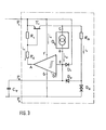
- FIG. 3 shows the circuit contained in the sensor.
- This circuit comprises, if it is realized in integrated bleitertechnik Hal, three output pins P 1, P and P 3.
- the optionally connectable capacitance C ⁇ which determines the time forming link, switched.
- This capacity is preferably integrated, e.g. B. in the form of a MOS capacitance. In this case, Pin deleted 2.
- Sensorübertragungslei- do g s end at P in P 1 and P3.
- the current source Q At the input E of the Schmitt trigger ST is the current source Q connected 2, charging with a dependent variable Current downstream capacitor C ⁇ .
- a resistor R 2 which determines the low-impedance state of the circuit, is connected to the output A of the Schmitt trigger ST and carries the current i 5 only in the charging phase of the capacitor C ⁇ during the interrogation phase. Furthermore, a switch T 1 is controlled via the output A of the Schmitt trigger, via which the current source Q 2 is only connected to the capacitor C during the charging phase.
- the circuit also contains means by which when the current source Q 2 is switched on, the capacitor C ⁇ is charged to a defined bias voltage, so that the actual charging phase of the capacitor C ⁇ always begins with a defined basic setting. These means are, for example, 2 or more diodes D 31 which are connected to the switch T 1 via a series resistor R 3 .
- the switch T 1 is, for example, a transistor whose base-emitter path is parallel to a resistor R 1 , which is connected in series with the resistor R 2 between the output A of the Schmitt trigger and pin P 1 .
- the Schmitt trigger ST is switched on in such a way that the output electrode A has a low or ground potential.
- current can flow through the resistor R 2 , as a result of which a sufficient voltage which controls the transistor T 1 drops across the resistor R1.
- the resistor R 2 has a relatively low resistance, for example 100-400 ⁇ and essentially determines the current i 1 according to FIG. 2.
- the capacitor C ⁇ is charged via the resistor R and the diode D 2 to the voltage value predetermined by the diodes D 3 .
- the diodes D 3 are parallel to the series connection of diode D 2 and capacitor C ⁇ ; the resistor R 3 is chosen so that the capacitor C ⁇ very quickly assumes the voltage given by the diodes D 3 . This ensures that the capacitor C ⁇ is always charged further from a defined basic charge at the beginning of the query phase.
- the further charging takes place via the current emitted by the current source Q 2 .
- This current is, for example, a function of the temperature prevailing in the region of the current source Q 2 .
- the current i m to which the capacitor C ⁇ is further charged, for example, is at a temperature T 1 T em-10 uA and changes with each degree of temperature change by about 1%.
- the capacitor C ⁇ is connected via a diode D 1 to the sensor line at the pin P 1 in such a way that after the interrogation phase t p , a short-term grounding of this sensor line leads to a discharge of the capacitor except for that caused by the di de D 1 certain flux voltage is possible.
- the earthing of the sensor line is triggered briefly by the microprocessor after the time t p . This ensures that when the sensor is interrogated again, the discharged state of the capacitor C ⁇ can be assumed.
- the current source Q 2 assumes that the current it emits is a function of temperature. This current can also be the function of a pressure, the brightness, the humidity of a speed or the flow rate.
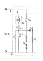
- the configuration of a Schmitt trigger results, for example, from FIG. 4.
- the circuit consists of the npn transistors T 3 , T 4 , the pnp transistor T 2 and the downstream transistor T 7 , through which the resistor R 2 is connected to ground is connected.
- the capacitor C ⁇ When the capacitor C ⁇ is discharged, no current can flow through the transistor T 4 , whose base is connected to the capacitance C ⁇ .
- the collector potential of the transistor T 4 thus rises, so that the transistor T 3 is turned on via the base resistor R 9 .
- a current now flows through the collector resistor R 6 of the transistor T 3 and via the emitter resistor R 8 , which is also the emitter resistor of the transistor T 4 .
- the transistor T 2 coupled on the base side with the resistor R 10 is also switched through, so that current flows from the resistors R 4 , R 5 via the voltage divider located in the collector branch of the transistor T 2 .
- the voltage drop across the resistor R 5 supplies the base-emitter voltage of the transistor T 7 , which is switched through with a corresponding resistor dimensioning, so that the resistor R 2 is connected to ground via the collector-emitter path of the transistor T 7 .
- FIG. 5 shows an embodiment for the current source Q 2 , which supplies a current i m dependent on the temperature.
- the circuit consists of the two NPN transistors T 5 and T 6 , the base-emitter path of the transistor T 5 being parallel to the collector base path of the transistor T 6 .
- the base collector path of the transistor T 5 is bridged by the high-resistance resistor R 11 , while a lower-resistance resistor R 12 is parallel to the base-emitter path of the transistor T 6 .
- the voltage U BE has, for example, a negative temperature coefficient of - 0.4% / K while the resistor R12 has a positive temperature coefficient of, for example, 0.5% / K. Because the flow is essentially through is determined, there is a current decrease of approximately 0.9% / K for each degree of temperature increase.
- the components can be selected so that with a degree of temperature increase the current decrease is ⁇ 1%.
- the absolute current at a defined temperature value can vary from source circuit to source circuit with the component tolerances. In this case it will make sense to adapt the capacitance C ⁇ to the absolute value of the current of the current source used in each case. This can also be done with the help of an automatic capacity adjustment.
- the circuit of FIG. 5 shows that the current becomes smaller and smaller at a very high temperature, so that the capacitance C ⁇ is charged more slowly. With increasing temperature T empe- thus increases the pulse width t 1 of FIG. 2.
- FIG. 6 shows another circuit option for safely discharging the capacitor C ⁇ after the end of the interrogation phase, in which case no additional grounding of the sensor line arriving at pin P 1 is required.
- FIG. 6 only the circuit part essential for the change compared to FIG. 3 is shown.
- the circuit parts, not shown, correspond to those of FIG. 3, the diode D 1 being omitted.
- FIG. 6 is parallel of a MOS field effect transistor T connected to the condenser 8 of the depletion type, the source C D ⁇ rain-route.
- the gate electrode of this transistor T 8 is connected to the sensor line 2a via a suitable series resistor R19.
- a protective circuit for surge peaks is arranged between the gate electrode and the ground line 2b.
- This circuit consists, for example, of a series of diodes D 8 connected in series , for the control of which a voltage of more than 5 volts is required.
- the gate potential at transistor T 8 returns to the value O and the transistor assumes its normally-on state, so that the capacitance C r can discharge via the MOS transistor.
- the circuit or sensor system according to the invention has the advantage that a quasi-digital transmission of the measured variable is possible without critical current or voltage levels and a simple evaluation routine can be carried out in a microprocessor.
Landscapes
- Physics & Mathematics (AREA)
- General Physics & Mathematics (AREA)
- Arrangements For Transmission Of Measured Signals (AREA)
- Cable Transmission Systems, Equalization Of Radio And Reduction Of Echo (AREA)
Applications Claiming Priority (2)
| Application Number | Priority Date | Filing Date | Title |
|---|---|---|---|
| DE19803013474 DE3013474A1 (de) | 1980-04-08 | 1980-04-08 | Sensorsystem |
| DE3013474 | 1980-04-08 |
Publications (1)
| Publication Number | Publication Date |
|---|---|
| EP0037502A1 true EP0037502A1 (fr) | 1981-10-14 |
Family
ID=6099505
Family Applications (1)
| Application Number | Title | Priority Date | Filing Date |
|---|---|---|---|
| EP81102134A Withdrawn EP0037502A1 (fr) | 1980-04-08 | 1981-03-21 | Système à capteur |
Country Status (3)
| Country | Link |
|---|---|
| EP (1) | EP0037502A1 (fr) |
| JP (1) | JPS56159800A (fr) |
| DE (1) | DE3013474A1 (fr) |
Cited By (5)
| Publication number | Priority date | Publication date | Assignee | Title |
|---|---|---|---|---|
| EP0501771A1 (fr) * | 1991-02-25 | 1992-09-02 | Nihon Protech System Co., Ltd. | Système de transmission d'information |
| DE4339958A1 (de) * | 1993-11-24 | 1995-06-01 | Bosch Gmbh Robert | Signalerfassungsvorrichtung |
| EP1251474A1 (fr) * | 2001-04-20 | 2002-10-23 | Micronas GmbH | Capteur à connexion bifilaire utilisant la modulation d'impulsions en largeur |
| US6868875B2 (en) * | 2000-03-08 | 2005-03-22 | Tibotec Bvba | Method and apparatus for dispensing a liquid into a series of wells |
| DE102012007776A1 (de) * | 2012-04-25 | 2013-10-31 | Brüel & Kjaer Vibro GmbH | Eindraht-Programmier- und Messkette |
Families Citing this family (1)
| Publication number | Priority date | Publication date | Assignee | Title |
|---|---|---|---|---|
| DE4323379A1 (de) * | 1993-07-13 | 1995-01-26 | Krieger Gmbh & Co Kg | Schaltungsanordnung zur Regelung der Leistung eines Heizelements einer Heizeinrichtung zum Trocknen einer laufenden Bahn |
Citations (2)
| Publication number | Priority date | Publication date | Assignee | Title |
|---|---|---|---|---|
| DE2625714A1 (de) * | 1975-06-18 | 1977-01-20 | Setron Erzeugung Elektronische | Verfahren zur messung physikalischer groessen und der elektrischen fernuebertragung des messwertes |
| DE2750175A1 (de) * | 1976-11-17 | 1978-05-18 | Bendix Corp | Datenuebertragungssystem mit analog- impulsbreite-digitalumwandlung |
Family Cites Families (2)
| Publication number | Priority date | Publication date | Assignee | Title |
|---|---|---|---|---|
| DE1423788A1 (de) * | 1961-06-21 | 1969-05-29 | Pepperl & Fuchs Ohg | Anordnung zur kontaktlosen Erzeugung von Schaltimpulsen oder Steuerbefehlen innerhalb einer Regel-oder Steueranlage od.dgl. |
| US3668676A (en) * | 1969-07-01 | 1972-06-06 | Nittan Co Ltd | Alarm device with means to locate an erroneously activated detector |
-
1980
- 1980-04-08 DE DE19803013474 patent/DE3013474A1/de not_active Ceased
-
1981
- 1981-03-21 EP EP81102134A patent/EP0037502A1/fr not_active Withdrawn
- 1981-04-07 JP JP5130881A patent/JPS56159800A/ja active Pending
Patent Citations (2)
| Publication number | Priority date | Publication date | Assignee | Title |
|---|---|---|---|---|
| DE2625714A1 (de) * | 1975-06-18 | 1977-01-20 | Setron Erzeugung Elektronische | Verfahren zur messung physikalischer groessen und der elektrischen fernuebertragung des messwertes |
| DE2750175A1 (de) * | 1976-11-17 | 1978-05-18 | Bendix Corp | Datenuebertragungssystem mit analog- impulsbreite-digitalumwandlung |
Cited By (7)
| Publication number | Priority date | Publication date | Assignee | Title |
|---|---|---|---|---|
| EP0501771A1 (fr) * | 1991-02-25 | 1992-09-02 | Nihon Protech System Co., Ltd. | Système de transmission d'information |
| DE4339958A1 (de) * | 1993-11-24 | 1995-06-01 | Bosch Gmbh Robert | Signalerfassungsvorrichtung |
| US6868875B2 (en) * | 2000-03-08 | 2005-03-22 | Tibotec Bvba | Method and apparatus for dispensing a liquid into a series of wells |
| EP1251474A1 (fr) * | 2001-04-20 | 2002-10-23 | Micronas GmbH | Capteur à connexion bifilaire utilisant la modulation d'impulsions en largeur |
| US7124655B2 (en) | 2001-04-20 | 2006-10-24 | Micronas Gmbh | Two-wire sensor for measuring a physical parameter |
| DE102012007776A1 (de) * | 2012-04-25 | 2013-10-31 | Brüel & Kjaer Vibro GmbH | Eindraht-Programmier- und Messkette |
| DE102012007776B4 (de) * | 2012-04-25 | 2014-06-26 | Brüel & Kjaer Vibro GmbH | Eindraht-Programmier- und Messkette |
Also Published As
| Publication number | Publication date |
|---|---|
| DE3013474A1 (de) | 1981-10-15 |
| JPS56159800A (en) | 1981-12-09 |
Similar Documents
| Publication | Publication Date | Title |
|---|---|---|
| EP0548495B1 (fr) | Procédé et circuit pour mesurer l'inductance d'une bobine | |
| EP0126846A2 (fr) | Capteur inductif | |
| DE3343885A1 (de) | Induktiver sensor | |
| WO1992021985A1 (fr) | Circuit de controle pour un capteur | |
| DE2942134C2 (fr) | ||
| DE4041032C2 (de) | Schaltungsanordnung zur Überwachung eines Lastkreises | |
| EP0037502A1 (fr) | Système à capteur | |
| EP0266501B1 (fr) | Procédé et arrangement de circuits pour la détection de l'état d'un capteur d'oxygène | |
| EP0698794A1 (fr) | Circuit de détection de tension trop basse | |
| DE3245008C2 (fr) | ||
| EP0280261A2 (fr) | Circuit pour la production d'un signal carré indépendant de la température à une grandeur mesurée | |
| DE2013413A1 (fr) | ||
| DE3905163C2 (fr) | ||
| DE2256009A1 (de) | Schaltungsanordnung zur wahrnehmung einer signalspannungsaenderung | |
| EP0128283A1 (fr) | Procédé et dispositif pour la conversion d'une valeur de température | |
| DE2713280C3 (de) | Funktionsüberprüfbare Feuermelderanlage | |
| DE10034866C2 (de) | Schaltungsanordnung | |
| DE1288138B (de) | Mit Stromuebernahme arbeitende Gatterschaltung | |
| DE1176249B (de) | Spannungsueberwachungs- und Kurzschliess-vorrichtung | |
| DE19828055B4 (de) | Schaltung zur Ansteuerung wenigstens eines induktiven Sensors | |
| DE2604160A1 (de) | Regeleinrichtung zur beeinflussung des der brennkraftmaschine zugefuehrten betriebsgemisches | |
| DE3818455C2 (fr) | ||
| DE3002646C2 (de) | Schaltungsanordnung zur Versorgung eines in CMOS-Technik ausgeführten elektronischen digitalen Geräts | |
| DE2154829C2 (de) | Schaltungsanordnung zur Messung der Frequenz einer Folge von Eingangsimpulsen | |
| DE102005020870B4 (de) | Sensorschaltung |
Legal Events
| Date | Code | Title | Description |
|---|---|---|---|
| PUAI | Public reference made under article 153(3) epc to a published international application that has entered the european phase |
Free format text: ORIGINAL CODE: 0009012 |
|
| AK | Designated contracting states |
Designated state(s): FR GB IT |
|
| STAA | Information on the status of an ep patent application or granted ep patent |
Free format text: STATUS: THE APPLICATION IS DEEMED TO BE WITHDRAWN |
|
| 18D | Application deemed to be withdrawn |
Effective date: 19820920 |
|
| RIN1 | Information on inventor provided before grant (corrected) |
Inventor name: NUTZ, KARL-DIETHER Inventor name: GERSTNER, DIETER, DR. |