EP0037293A1 - Traggestell für die Herstellung von Werkstücken, insbesondere von Autokarosserien, im Fliessbandverfahren - Google Patents
Traggestell für die Herstellung von Werkstücken, insbesondere von Autokarosserien, im Fliessbandverfahren Download PDFInfo
- Publication number
- EP0037293A1 EP0037293A1 EP81400293A EP81400293A EP0037293A1 EP 0037293 A1 EP0037293 A1 EP 0037293A1 EP 81400293 A EP81400293 A EP 81400293A EP 81400293 A EP81400293 A EP 81400293A EP 0037293 A1 EP0037293 A1 EP 0037293A1
- Authority
- EP
- European Patent Office
- Prior art keywords
- products
- assembled
- swing
- assembly
- arches
- Prior art date
- Legal status (The legal status is an assumption and is not a legal conclusion. Google has not performed a legal analysis and makes no representation as to the accuracy of the status listed.)
- Granted
Links
- 238000004873 anchoring Methods 0.000 claims abstract description 9
- 238000009434 installation Methods 0.000 description 4
- 239000003381 stabilizer Substances 0.000 description 3
- 241000282461 Canis lupus Species 0.000 description 2
- 238000006073 displacement reaction Methods 0.000 description 1
- 238000012423 maintenance Methods 0.000 description 1
- 238000012986 modification Methods 0.000 description 1
- 230000004048 modification Effects 0.000 description 1
- 238000007789 sealing Methods 0.000 description 1
Images

Classifications
-
- B—PERFORMING OPERATIONS; TRANSPORTING
- B65—CONVEYING; PACKING; STORING; HANDLING THIN OR FILAMENTARY MATERIAL
- B65G—TRANSPORT OR STORAGE DEVICES, e.g. CONVEYORS FOR LOADING OR TIPPING, SHOP CONVEYOR SYSTEMS OR PNEUMATIC TUBE CONVEYORS
- B65G17/00—Conveyors having an endless traction element, e.g. a chain, transmitting movement to a continuous or substantially-continuous load-carrying surface or to a series of individual load-carriers; Endless-chain conveyors in which the chains form the load-carrying surface
- B65G17/20—Conveyors having an endless traction element, e.g. a chain, transmitting movement to a continuous or substantially-continuous load-carrying surface or to a series of individual load-carriers; Endless-chain conveyors in which the chains form the load-carrying surface comprising load-carriers suspended from overhead traction chains
-
- B—PERFORMING OPERATIONS; TRANSPORTING
- B62—LAND VEHICLES FOR TRAVELLING OTHERWISE THAN ON RAILS
- B62D—MOTOR VEHICLES; TRAILERS
- B62D65/00—Designing, manufacturing, e.g. assembling, facilitating disassembly, or structurally modifying motor vehicles or trailers, not otherwise provided for
- B62D65/02—Joining sub-units or components to, or positioning sub-units or components with respect to, body shell or other sub-units or components
- B62D65/18—Transportation, conveyor or haulage systems specially adapted for motor vehicle or trailer assembly lines
-
- B—PERFORMING OPERATIONS; TRANSPORTING
- B65—CONVEYING; PACKING; STORING; HANDLING THIN OR FILAMENTARY MATERIAL
- B65G—TRANSPORT OR STORAGE DEVICES, e.g. CONVEYORS FOR LOADING OR TIPPING, SHOP CONVEYOR SYSTEMS OR PNEUMATIC TUBE CONVEYORS
- B65G2201/00—Indexing codes relating to handling devices, e.g. conveyors, characterised by the type of product or load being conveyed or handled
- B65G2201/02—Articles
Definitions
- the present invention relates to a multipurpose swing for c manufactures ashamed assembly, and in particular for motor vehicle production lines.
- the object of the present invention is to remedy the aforementioned drawbacks by the use of a single standard translation means throughout the assembly line, capable, however, of providing optimum freedom of access to the entire product. throughout its various stages of assembly, and this both for the serving staff as for the means of supply of spare parts and tools.
- the overhead swing conveyor is apparently the most suitable translation system to meet these criteria, because it offers great flexibility in positioning in space, as necessary, products to be assembled, making it ergonomically reliable, at height normal human, all manual operations to practice on these products, without having to resort to major civil engineering work for the establishment of the production chain.
- such an installation due to the more modest investments and the lower technical skills which it implies, is particularly suitable for the realization of assembly factories in developing countries.
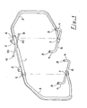
- the multipurpose swing for assembly lines of manipulated products, in particular of motor vehicles, comprising at least one upper element for hooking to a drive device by air conveyor consists of: two vertical hoops, substantially C-shaped, wide open, each separately connecting the upper attachment element to at least one separate lower stud for anchoring the base structure of the products to be assembled, said hoops being independently articulated around a substantially vertical axis with a large clearance allowing easy access to all of said products during all of their assembly.
- each of the arches, respectively located at the front and at the rear of the swing is directly pivotally mounted on the upper hooking element, and articulated at its lower end in the center of a separate pair of anchor studs, the connecting element between said pairs of anchor studs being constituted solely, during the period of use, by the underbody structure of the products to be assembled, thus ensuring great accessibility to the lower parts of this structure.
- each anchoring stud is provided with means for locking the base structure of the products to be assembled on said swing.
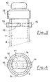
- each locking means is constituted by a rotary lock whose rotation of the head, of a shape known per se substantially parallelepiped in order to come to engage in suitable housings of the base structure of the products to be assembled, is ensured by the cooperation of an uninterrupted suite of four control ramps substantially shaped like wolf teeth formed on the lateral surface of the cylindrical bearing surface for pivoting the lock with at least one radial lug secured to a ring mounted vertically sliding around the lock body, so that each lifting caused by this sliding ring generates a quarter turn rotation of the lock head.
- the lifting of the sliding ring causing the rotation of the lock head can be automatically ensured by the presence of ramps or stops judiciously arranged at the appropriate stations on the route of the assembly line, to carry out the locking and unlocking of the products to be assembled.
- the housings of their base structure for the anchoring and locking studs may very advantageously be constituted by the housings for receiving and positioning the jack jack head under their frame-chassis.
- the upper attachment element comprises a horizontal crossbar provided with rollers free in rotation at each of its ends, forming horizontal stabilizer by cooperation in a manner known per se of said rollers with lateral guide rails integral with the support structure of the overhead conveyor in order to prevent any swinging of the assembly during interventions on the products being assembled.
- the swing comprising an upper element 1 for hooking by means of lugs 2 suitable for any drive device by overhead conveyor is made up in accordance with the object of the invention.
- two vertical arches substantially C-shaped wide open, respectively located at the front and rear of said swing, and each separately connecting the upper element 1 for attachment to a separate couple of studs anchor 4 for the base structure of the products to be assembled, constituted in the case of FIGS. 2a to 2f by the frame-chassis 5 of motor vehicles.
- Each of the two poles 3 is respectively pivotally mounted, using a first yoke 6, on the upper attachment element 1, and at its lower end, on a second yoke 7 secured to the center of a tube of link 8 raised at its ends to define each distinct pair of anchor studs 4.
- the hoops 3 are therefore independently articulated around a substantially vertical axis with a large angular movement, of the order of 180 degrees, allowing as clearly shown in Figures 2a to 2f easy access to all of the products, in l 'occurrence of motor vehicles, during all of their assembly.
- the only connecting and stiffening element between the separate pairs of anchor studs 4 is only constituted, during the period of use, by the base structure 5 of the products to be assembled, also ensuring great accessibility to the lower parts. of this structure, while lightening the swings during their circuit back empty.
- the interventions can be carried out without any discomfort on approximately 95% of the total surface of the products to be assembled, and it suffices for a small displacement of said hoops 3, printed manually by an operator or by an appropriate device located at the desired location on the assembly line to release the remaining 5%.
- the large deflection of the hoops 3 proves to be very useful for completely freeing the front or rear part of the products to be assembled, in particular when supplying large elements or for facilitating the evacuation at the end of the chain of products. finished.
- each anchoring stud 4 is provided with a locking means 9 for the base structure 5 of the products to be assembled on the swing.
- the upper hooking element 1 comprises a horizontal transverse bar 10 provided with rollers 11 which are free to rotate at each of its ends, forming a horizontal stabilizer by cooperation, in a manner known per se, of said rollers 11 with lateral guide rails, not shown in the appended figures, integral with the support structure of the overhead conveyor in order to prevent any rocking of the assembly during manual or automated interventions on the products being assembled.
- the locking means 9 may be constituted by a rotary lock with manual actuation, of the type shown in FIGS. 3 and 4, and comprising a head 12, of a shape known per se substantially parallelepipedal in order to come s' engage in an appropriate housing of the base structure 5 of the products to be assembled, provided with a knurled lower flange 13 allowing it to impart an alternating movement of rotation of 90 degrees, and extended by a cylindrical bearing 14, swiveling in each upper end connecting tubes 8 forming the pairs of anchoring studs 4, and limited in translation and rotation by the cooperation of stops 15 screwed radially in said cylindrical seat 14 and of corresponding horizontal openings 16 each made sensi completely on a quarter of the section of said tubes 8 near the ends thereof, so as to allow only a quarter-turn rotation of said locking heads 12.
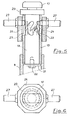
- the latter also consists of a rotary lock comprising a head 17 of a shape similar to the head of the preceding lock, extended by a cylindrical bearing 18 , mounted free in rotation in a tubular body 19 of a bolt screwed at the end of the tubes 8 of anchoring pads 4, and immobilized in translation in said body 19 of a bolt by the simultaneous action of an upper support flange 20 and d 'a lower thrust washer 21 secured by axial screw 22 to said cylindrical bearing 18.
- the rotation of the locking head 17 is then ensured by the cooperation of an uninterrupted series of four control ramps 23 substantially shaped teeth of wolf practiced on the lateral surface of the litter 18 with two diametrically opposite lugs 24, sliding in corresponding vertical openings 25 practiced in the body 19 of latch, and ra dialed integral with a ring 26 mounted vertically sliding around said lock body 19, so that each caused uplift of this ring 26 generates a quarter turn rotation of the lock head 17.
- Each lug 24 also has an extension 27 extending externally to the sliding ring 26, and forming an operating member of said locking means.
- the lifting of the sliding ring 26 generating the rotation of the latch head 17 can thus indifferently, thanks to this operating member, be ensured either manually or automatically by cooperation of said extensions 27 with ramps or retractable stops judiciously disposed at suitable positions on the route of the assembly line.
- the housings of their base structure 5 for the anchoring studs 4 and for locking 9 could very advantageously be constituted by the receiving housings and positioning the jack head under their frame-chassis.
- the versatile swing, object of the present invention therefore provides by simple means therefore reliable and inexpensive, optimum accessibility to all of the elements of the products to be assembled, throughout the various stages of their development, whether for operators or for the means of supplying spare parts and tools. It therefore lends itself as well to use on relatively rudimentary chains with a majority of manual operations, as on highly automated chains requiring, for example, great freedom of access and movement for the working arms of programmable controllers, each swing can very well be effectively immobilized and stabilized by appropriate means, associated inter alia with the horizontal stabilizer described above, during the operating times of said automata.
- the locking means 9 may be provided with sealing sleeves ensuring their protection during the passage of the swings in installations for treating the surface of the products to be assembled.
Landscapes
- Engineering & Computer Science (AREA)
- Mechanical Engineering (AREA)
- Manufacturing & Machinery (AREA)
- Chemical & Material Sciences (AREA)
- Combustion & Propulsion (AREA)
- Transportation (AREA)
- Automobile Manufacture Line, Endless Track Vehicle, Trailer (AREA)
- Automatic Assembly (AREA)
- Chain Conveyers (AREA)
- Gears, Cams (AREA)
- Connection Of Motors, Electrical Generators, Mechanical Devices, And The Like (AREA)
- Vehicle Body Suspensions (AREA)
- Wire Processing (AREA)
Priority Applications (1)
| Application Number | Priority Date | Filing Date | Title |
|---|---|---|---|
| AT81400293T ATE3265T1 (de) | 1980-04-02 | 1981-02-26 | Traggestell fuer die herstellung von werkstuecken, insbesondere von autokarosserien, im fliessbandverfahren. |
Applications Claiming Priority (2)
| Application Number | Priority Date | Filing Date | Title |
|---|---|---|---|
| FR8007463A FR2479785A1 (fr) | 1980-04-02 | 1980-04-02 | Balancelle polyvalente pour chaines d'assemblage de produits manufactures, notamment de vehicules automobiles |
| FR8007463 | 1980-04-02 |
Publications (2)
| Publication Number | Publication Date |
|---|---|
| EP0037293A1 true EP0037293A1 (de) | 1981-10-07 |
| EP0037293B1 EP0037293B1 (de) | 1983-05-11 |
Family
ID=9240469
Family Applications (1)
| Application Number | Title | Priority Date | Filing Date |
|---|---|---|---|
| EP81400293A Expired EP0037293B1 (de) | 1980-04-02 | 1981-02-26 | Traggestell für die Herstellung von Werkstücken, insbesondere von Autokarosserien, im Fliessbandverfahren |
Country Status (8)
| Country | Link |
|---|---|
| US (1) | US4381055A (de) |
| EP (1) | EP0037293B1 (de) |
| JP (1) | JPS5719212A (de) |
| AT (1) | ATE3265T1 (de) |
| DE (1) | DE3160249D1 (de) |
| ES (1) | ES264919Y (de) |
| FR (1) | FR2479785A1 (de) |
| PT (1) | PT72766B (de) |
Cited By (3)
| Publication number | Priority date | Publication date | Assignee | Title |
|---|---|---|---|---|
| NL9201707A (nl) * | 1991-10-03 | 1993-05-03 | Mitsubishi Motors Corp | Transportinrichting voor werkstukken en transportwijze voor werkstukken. |
| DE202007009016U1 (de) | 2007-06-26 | 2008-11-13 | Kuka Systems Gmbh | Fördereinrichtung für Bauteile, insbesondere Fahrzeugkarosserien |
| CN100518557C (zh) * | 2004-07-12 | 2009-07-29 | 森蒂内工程(马)有限公司 | 装配成形器支座的装置和方法 |
Families Citing this family (10)
| Publication number | Priority date | Publication date | Assignee | Title |
|---|---|---|---|---|
| DE3543193C1 (de) * | 1985-12-06 | 1987-03-26 | Bayerische Motoren Werke Ag | Haengebahnfoerderanlage zum Transport von Karosserien |
| JPH058248Y2 (de) * | 1986-04-18 | 1993-03-02 | ||
| DE3642431C1 (de) * | 1986-12-12 | 1988-05-19 | Bayerische Motoren Werke Ag | Foerdereinrichtung zum Foerdern von Kraftfahrzeugkarosserien |
| NZ241415A (en) * | 1992-01-27 | 1995-04-27 | Air New Zealand Ltd | Gas turbine engine transporting frames |
| US5427618A (en) * | 1993-08-12 | 1995-06-27 | Haddix; Dennis W. | Fascia buck spindle |
| DE4413256C2 (de) * | 1994-04-16 | 1997-02-06 | Bayerische Motoren Werke Ag | Transportgehänge für eine Fahrzeug-Karosserie |
| DE10002481B4 (de) * | 2000-01-21 | 2006-07-27 | Audi Ag | Transportgehänge für eine zu transportierende Fahrzeugkarosserie |
| US7568678B2 (en) * | 2007-03-20 | 2009-08-04 | Larry Hammond | Apparatus for removing and reinstalling the hardtop of an automobile |
| EP2923925A3 (de) * | 2014-03-27 | 2016-01-13 | Cpm S.P.A. | Universeller gleichgewichtshalter zum transportieren von fahrzeugkarosserien und transportanlage damit |
| US11787666B2 (en) * | 2017-04-13 | 2023-10-17 | Brent Robert Zobel | Lifting apparatus |
Citations (3)
| Publication number | Priority date | Publication date | Assignee | Title |
|---|---|---|---|---|
| DE765899C (de) * | 1935-06-27 | 1954-05-10 | Opel Adam Ag | Verfahren zum Einbau des Motors und des Getriebes in Kraftfahrzeuge |
| US2796973A (en) * | 1947-05-17 | 1957-06-25 | Mechanical Handling Sys Inc | Load carriers for use in overhead trolley conveyor systems |
| DE2600348A1 (de) * | 1976-01-07 | 1977-07-14 | Peter Pleger | Transporteinrichtung fuer im fliessbandverfahren bearbeitbare autokarosserien |
Family Cites Families (4)
| Publication number | Priority date | Publication date | Assignee | Title |
|---|---|---|---|---|
| FR571013A (fr) * | 1923-09-24 | 1924-05-10 | Dispositif de façonnage multiple | |
| US2664993A (en) * | 1947-05-17 | 1954-01-05 | Mechanical Handling Sys Inc | Load carrier for use in overhead trolley conveyer systems |
| US2595182A (en) * | 1948-10-07 | 1952-04-29 | Rca Corp | Adjustable carrier for conveyer systems |
| DE2356799A1 (de) * | 1973-11-14 | 1975-05-15 | Scharmann & Co | Horizontal-bohr- und fraeswerk, mit einem die werkzeuge tragenden werkzeugmagazin |
-
1980
- 1980-04-02 FR FR8007463A patent/FR2479785A1/fr active Granted
-
1981
- 1981-02-26 DE DE8181400293T patent/DE3160249D1/de not_active Expired
- 1981-02-26 AT AT81400293T patent/ATE3265T1/de not_active IP Right Cessation
- 1981-02-26 EP EP81400293A patent/EP0037293B1/de not_active Expired
- 1981-03-11 US US06/242,673 patent/US4381055A/en not_active Expired - Fee Related
- 1981-03-30 ES ES1981264919U patent/ES264919Y/es not_active Expired
- 1981-03-30 PT PT72766A patent/PT72766B/pt unknown
- 1981-03-30 JP JP4566681A patent/JPS5719212A/ja active Pending
Patent Citations (3)
| Publication number | Priority date | Publication date | Assignee | Title |
|---|---|---|---|---|
| DE765899C (de) * | 1935-06-27 | 1954-05-10 | Opel Adam Ag | Verfahren zum Einbau des Motors und des Getriebes in Kraftfahrzeuge |
| US2796973A (en) * | 1947-05-17 | 1957-06-25 | Mechanical Handling Sys Inc | Load carriers for use in overhead trolley conveyor systems |
| DE2600348A1 (de) * | 1976-01-07 | 1977-07-14 | Peter Pleger | Transporteinrichtung fuer im fliessbandverfahren bearbeitbare autokarosserien |
Cited By (3)
| Publication number | Priority date | Publication date | Assignee | Title |
|---|---|---|---|---|
| NL9201707A (nl) * | 1991-10-03 | 1993-05-03 | Mitsubishi Motors Corp | Transportinrichting voor werkstukken en transportwijze voor werkstukken. |
| CN100518557C (zh) * | 2004-07-12 | 2009-07-29 | 森蒂内工程(马)有限公司 | 装配成形器支座的装置和方法 |
| DE202007009016U1 (de) | 2007-06-26 | 2008-11-13 | Kuka Systems Gmbh | Fördereinrichtung für Bauteile, insbesondere Fahrzeugkarosserien |
Also Published As
| Publication number | Publication date |
|---|---|
| PT72766B (fr) | 1982-03-22 |
| US4381055A (en) | 1983-04-26 |
| ATE3265T1 (de) | 1983-05-15 |
| PT72766A (fr) | 1981-04-01 |
| FR2479785A1 (fr) | 1981-10-09 |
| EP0037293B1 (de) | 1983-05-11 |
| ES264919U (es) | 1982-11-16 |
| DE3160249D1 (en) | 1983-06-16 |
| FR2479785B1 (de) | 1984-07-20 |
| JPS5719212A (en) | 1982-02-01 |
| ES264919Y (es) | 1983-06-01 |
Similar Documents
| Publication | Publication Date | Title |
|---|---|---|
| EP0037293A1 (de) | Traggestell für die Herstellung von Werkstücken, insbesondere von Autokarosserien, im Fliessbandverfahren | |
| FR2480631A1 (fr) | Procede de tri ou de transport et installation et chariot pour sa mise en oeuvre | |
| FR2503065A1 (fr) | Dispositif destine a equiper un marbre de controle et/ou de reparation de carrosseries de voitures automobiles | |
| FR2595087A1 (fr) | Systeme de manutention monorail utilisant un chariot sureleve par rapport a un plan d'entreposage, notamment pour une fonderie | |
| FR2653085A1 (fr) | Systeme de transport du type a plate-forme roulante automotrice. | |
| FR2689090A1 (fr) | Véhicule de convoyage d'avion au sol. | |
| EP3421409B1 (de) | Handling-portalkran und handling-system, das einen solchen portalkran umfasst | |
| FR2929919A1 (fr) | Procede de retournement d'une structure et outillage associe a un tel procede. | |
| FR2497184A1 (fr) | Engin de levage | |
| FR2725176A1 (fr) | Machine de construction de voie ferree | |
| EP1711394A1 (de) | Vorrichtung für den transport und die positionierung einer kraftfahrzeugaufbauanordnung | |
| FR2585312A1 (fr) | Plaque tournante pour vehicules automobiles | |
| FR2528000A1 (fr) | Installation de trans-port, en particulier pour la manutention suspendue | |
| FR2478046A1 (fr) | Installation de manutention | |
| WO2009112772A2 (fr) | Wagon de manutention de charges lourdes, notamment de rails, et utilisation d'un tel wagon en présence d'une caténaire | |
| FR2594457A1 (fr) | Dispositif de pose mobile pour des elements de ponts et des pontons | |
| FR2851982A1 (fr) | Potence de suspension, et conteneur de pieces equipe d'au moins une telle potence de suspension | |
| CH619656A5 (en) | Handling device comprising an overhead track | |
| FR2653078A1 (fr) | Plan de chargement composite pour vehicule porte-voitures. | |
| FR2611682A1 (fr) | Support ou passerelle deplacable pour amener un vehicule en position surelevee | |
| FR2597460A1 (fr) | Engin mobile de transport et manutention d'objets, plus particulierement pour cimetiere | |
| FR2689844A1 (fr) | Installation pour le traitement de véhicules automobiles usagés ou accidentés, notamment le démontage de leurs organes mécaniques. | |
| FR2674810A1 (fr) | Chariot pour la manutention d'une charge equipee de roues. | |
| EP0623488A1 (de) | Einrichtung zum Stabilsieren einer lasttragenden Fahrzeugladefläche | |
| FR2791085A1 (fr) | Perfectionnements apportes a un dispositif d'acces a une citerne |
Legal Events
| Date | Code | Title | Description |
|---|---|---|---|
| PUAI | Public reference made under article 153(3) epc to a published international application that has entered the european phase |
Free format text: ORIGINAL CODE: 0009012 |
|
| AK | Designated contracting states |
Designated state(s): AT BE CH DE GB IT LU NL SE |
|
| 17P | Request for examination filed |
Effective date: 19810910 |
|
| ITF | It: translation for a ep patent filed | ||
| GRAA | (expected) grant |
Free format text: ORIGINAL CODE: 0009210 |
|
| AK | Designated contracting states |
Designated state(s): AT BE CH DE GB IT LI LU NL SE |
|
| REF | Corresponds to: |
Ref document number: 3265 Country of ref document: AT Date of ref document: 19830515 Kind code of ref document: T |
|
| REF | Corresponds to: |
Ref document number: 3160249 Country of ref document: DE Date of ref document: 19830616 |
|
| PGFP | Annual fee paid to national office [announced via postgrant information from national office to epo] |
Ref country code: CH Payment date: 19840118 Year of fee payment: 4 |
|
| PG25 | Lapsed in a contracting state [announced via postgrant information from national office to epo] |
Ref country code: LU Free format text: LAPSE BECAUSE OF NON-PAYMENT OF DUE FEES Effective date: 19840229 |
|
| PLBE | No opposition filed within time limit |
Free format text: ORIGINAL CODE: 0009261 |
|
| STAA | Information on the status of an ep patent application or granted ep patent |
Free format text: STATUS: NO OPPOSITION FILED WITHIN TIME LIMIT |
|
| 26N | No opposition filed | ||
| PGFP | Annual fee paid to national office [announced via postgrant information from national office to epo] |
Ref country code: SE Payment date: 19841231 Year of fee payment: 5 Ref country code: BE Payment date: 19841231 Year of fee payment: 5 |
|
| PGFP | Annual fee paid to national office [announced via postgrant information from national office to epo] |
Ref country code: LU Payment date: 19860404 Year of fee payment: 6 |
|
| PGFP | Annual fee paid to national office [announced via postgrant information from national office to epo] |
Ref country code: NL Payment date: 19870228 Year of fee payment: 7 Ref country code: AT Payment date: 19870228 Year of fee payment: 7 |
|
| REG | Reference to a national code |
Ref country code: GB Ref legal event code: 746 |
|
| PG25 | Lapsed in a contracting state [announced via postgrant information from national office to epo] |
Ref country code: AT Effective date: 19890226 |
|
| PG25 | Lapsed in a contracting state [announced via postgrant information from national office to epo] |
Ref country code: SE Effective date: 19890227 |
|
| PG25 | Lapsed in a contracting state [announced via postgrant information from national office to epo] |
Ref country code: LI Effective date: 19890228 Ref country code: CH Effective date: 19890228 Ref country code: BE Effective date: 19890228 |
|
| BERE | Be: lapsed |
Owner name: REGIE NATIONALE DES USINES RENAULT Effective date: 19890228 |
|
| PG25 | Lapsed in a contracting state [announced via postgrant information from national office to epo] |
Ref country code: NL Effective date: 19890901 |
|
| NLV4 | Nl: lapsed or anulled due to non-payment of the annual fee | ||
| REG | Reference to a national code |
Ref country code: CH Ref legal event code: PL |
|
| PGFP | Annual fee paid to national office [announced via postgrant information from national office to epo] |
Ref country code: DE Payment date: 19901213 Year of fee payment: 11 |
|
| PGFP | Annual fee paid to national office [announced via postgrant information from national office to epo] |
Ref country code: GB Payment date: 19910117 Year of fee payment: 11 |
|
| ITTA | It: last paid annual fee | ||
| PG25 | Lapsed in a contracting state [announced via postgrant information from national office to epo] |
Ref country code: GB Effective date: 19920226 |
|
| GBPC | Gb: european patent ceased through non-payment of renewal fee | ||
| PG25 | Lapsed in a contracting state [announced via postgrant information from national office to epo] |
Ref country code: DE Effective date: 19921103 |
|
| EUG | Se: european patent has lapsed |
Ref document number: 81400293.7 Effective date: 19900118 |