EP0037281A2 - Ofen zum Verbrennen festen Brennstoffs und katalytischer Konverter - Google Patents
Ofen zum Verbrennen festen Brennstoffs und katalytischer Konverter Download PDFInfo
- Publication number
- EP0037281A2 EP0037281A2 EP81301389A EP81301389A EP0037281A2 EP 0037281 A2 EP0037281 A2 EP 0037281A2 EP 81301389 A EP81301389 A EP 81301389A EP 81301389 A EP81301389 A EP 81301389A EP 0037281 A2 EP0037281 A2 EP 0037281A2
- Authority
- EP
- European Patent Office
- Prior art keywords
- converter
- stove
- combustion chamber
- opening
- catalytic
- Prior art date
- Legal status (The legal status is an assumption and is not a legal conclusion. Google has not performed a legal analysis and makes no representation as to the accuracy of the status listed.)
- Granted
Links
- 230000003197 catalytic effect Effects 0.000 title claims abstract description 102
- 239000004449 solid propellant Substances 0.000 title claims abstract description 6
- 238000002485 combustion reaction Methods 0.000 claims description 93
- 239000007789 gas Substances 0.000 claims description 13
- 239000000567 combustion gas Substances 0.000 claims description 10
- WHRZCXAVMTUTDD-UHFFFAOYSA-N 1h-furo[2,3-d]pyrimidin-2-one Chemical compound N1C(=O)N=C2OC=CC2=C1 WHRZCXAVMTUTDD-UHFFFAOYSA-N 0.000 claims description 8
- 235000006173 Larrea tridentata Nutrition 0.000 claims description 8
- 244000073231 Larrea tridentata Species 0.000 claims description 8
- 229960002126 creosote Drugs 0.000 claims description 8
- 239000011521 glass Substances 0.000 claims description 8
- KDLHZDBZIXYQEI-UHFFFAOYSA-N Palladium Chemical compound [Pd] KDLHZDBZIXYQEI-UHFFFAOYSA-N 0.000 claims description 6
- BASFCYQUMIYNBI-UHFFFAOYSA-N platinum Chemical compound [Pt] BASFCYQUMIYNBI-UHFFFAOYSA-N 0.000 claims description 6
- 229910052751 metal Inorganic materials 0.000 claims description 5
- 239000002184 metal Substances 0.000 claims description 5
- 238000004891 communication Methods 0.000 claims description 3
- 229910052763 palladium Inorganic materials 0.000 claims description 3
- 229910052697 platinum Inorganic materials 0.000 claims description 3
- 230000001590 oxidative effect Effects 0.000 claims description 2
- 239000011248 coating agent Substances 0.000 claims 2
- 238000000576 coating method Methods 0.000 claims 2
- 241000894007 species Species 0.000 claims 2
- 230000005484 gravity Effects 0.000 claims 1
- 230000002093 peripheral effect Effects 0.000 claims 1
- 239000002023 wood Substances 0.000 abstract description 43
- 239000003245 coal Substances 0.000 abstract description 6
- 239000000446 fuel Substances 0.000 description 20
- QVGXLLKOCUKJST-UHFFFAOYSA-N atomic oxygen Chemical compound [O] QVGXLLKOCUKJST-UHFFFAOYSA-N 0.000 description 6
- 238000009413 insulation Methods 0.000 description 6
- 229910052760 oxygen Inorganic materials 0.000 description 6
- 239000001301 oxygen Substances 0.000 description 6
- 239000000919 ceramic Substances 0.000 description 5
- 239000000463 material Substances 0.000 description 5
- 230000005855 radiation Effects 0.000 description 4
- 239000000779 smoke Substances 0.000 description 4
- 239000010935 stainless steel Substances 0.000 description 4
- 229910001220 stainless steel Inorganic materials 0.000 description 4
- 239000000126 substance Substances 0.000 description 4
- 239000003039 volatile agent Substances 0.000 description 4
- OKTJSMMVPCPJKN-UHFFFAOYSA-N Carbon Chemical compound [C] OKTJSMMVPCPJKN-UHFFFAOYSA-N 0.000 description 3
- 238000009825 accumulation Methods 0.000 description 3
- 229910052799 carbon Inorganic materials 0.000 description 3
- 239000003054 catalyst Substances 0.000 description 3
- 238000010276 construction Methods 0.000 description 2
- 230000000694 effects Effects 0.000 description 2
- 239000003344 environmental pollutant Substances 0.000 description 2
- 238000010438 heat treatment Methods 0.000 description 2
- 238000009434 installation Methods 0.000 description 2
- 238000011068 loading method Methods 0.000 description 2
- 230000003647 oxidation Effects 0.000 description 2
- 238000007254 oxidation reaction Methods 0.000 description 2
- 239000002245 particle Substances 0.000 description 2
- 239000008188 pellet Substances 0.000 description 2
- 231100000719 pollutant Toxicity 0.000 description 2
- 239000000047 product Substances 0.000 description 2
- 239000011269 tar Substances 0.000 description 2
- 239000002028 Biomass Substances 0.000 description 1
- UGFAIRIUMAVXCW-UHFFFAOYSA-N Carbon monoxide Chemical compound [O+]#[C-] UGFAIRIUMAVXCW-UHFFFAOYSA-N 0.000 description 1
- 206010067482 No adverse event Diseases 0.000 description 1
- 229910000831 Steel Inorganic materials 0.000 description 1
- 229910045601 alloy Inorganic materials 0.000 description 1
- 239000000956 alloy Substances 0.000 description 1
- WYTGDNHDOZPMIW-RCBQFDQVSA-N alstonine Natural products C1=CC2=C3C=CC=CC3=NC2=C2N1C[C@H]1[C@H](C)OC=C(C(=O)OC)[C@H]1C2 WYTGDNHDOZPMIW-RCBQFDQVSA-N 0.000 description 1
- PNEYBMLMFCGWSK-UHFFFAOYSA-N aluminium oxide Inorganic materials [O-2].[O-2].[O-2].[Al+3].[Al+3] PNEYBMLMFCGWSK-UHFFFAOYSA-N 0.000 description 1
- 239000011449 brick Substances 0.000 description 1
- 239000006227 byproduct Substances 0.000 description 1
- 230000001413 cellular effect Effects 0.000 description 1
- 238000006243 chemical reaction Methods 0.000 description 1
- 238000004140 cleaning Methods 0.000 description 1
- 238000009833 condensation Methods 0.000 description 1
- 230000005494 condensation Effects 0.000 description 1
- 238000013461 design Methods 0.000 description 1
- 230000007613 environmental effect Effects 0.000 description 1
- 238000001125 extrusion Methods 0.000 description 1
- 238000010304 firing Methods 0.000 description 1
- 239000003546 flue gas Substances 0.000 description 1
- 239000003517 fume Substances 0.000 description 1
- 230000001535 kindling effect Effects 0.000 description 1
- 238000000034 method Methods 0.000 description 1
- 238000002156 mixing Methods 0.000 description 1
- 238000012986 modification Methods 0.000 description 1
- 230000004048 modification Effects 0.000 description 1
- 230000001473 noxious effect Effects 0.000 description 1
- 238000013021 overheating Methods 0.000 description 1
- 239000003209 petroleum derivative Substances 0.000 description 1
- 239000010970 precious metal Substances 0.000 description 1
- 230000002265 prevention Effects 0.000 description 1
- 238000000197 pyrolysis Methods 0.000 description 1
- 230000000717 retained effect Effects 0.000 description 1
- 230000000630 rising effect Effects 0.000 description 1
- 239000010959 steel Substances 0.000 description 1
- 230000002459 sustained effect Effects 0.000 description 1
- 238000012360 testing method Methods 0.000 description 1
- 238000012546 transfer Methods 0.000 description 1
Images


Classifications
-
- F—MECHANICAL ENGINEERING; LIGHTING; HEATING; WEAPONS; BLASTING
- F24—HEATING; RANGES; VENTILATING
- F24B—DOMESTIC STOVES OR RANGES FOR SOLID FUELS; IMPLEMENTS FOR USE IN CONNECTION WITH STOVES OR RANGES
- F24B13/00—Details solely applicable to stoves or ranges burning solid fuels
-
- F—MECHANICAL ENGINEERING; LIGHTING; HEATING; WEAPONS; BLASTING
- F23—COMBUSTION APPARATUS; COMBUSTION PROCESSES
- F23B—METHODS OR APPARATUS FOR COMBUSTION USING ONLY SOLID FUEL
- F23B5/00—Combustion apparatus with arrangements for burning uncombusted material from primary combustion
-
- F—MECHANICAL ENGINEERING; LIGHTING; HEATING; WEAPONS; BLASTING
- F24—HEATING; RANGES; VENTILATING
- F24B—DOMESTIC STOVES OR RANGES FOR SOLID FUELS; IMPLEMENTS FOR USE IN CONNECTION WITH STOVES OR RANGES
- F24B1/00—Stoves or ranges
- F24B1/006—Stoves or ranges incorporating a catalytic combustor
-
- F—MECHANICAL ENGINEERING; LIGHTING; HEATING; WEAPONS; BLASTING
- F24—HEATING; RANGES; VENTILATING
- F24B—DOMESTIC STOVES OR RANGES FOR SOLID FUELS; IMPLEMENTS FOR USE IN CONNECTION WITH STOVES OR RANGES
- F24B13/00—Details solely applicable to stoves or ranges burning solid fuels
- F24B13/004—Doors specially adapted for stoves or ranges
-
- F—MECHANICAL ENGINEERING; LIGHTING; HEATING; WEAPONS; BLASTING
- F24—HEATING; RANGES; VENTILATING
- F24B—DOMESTIC STOVES OR RANGES FOR SOLID FUELS; IMPLEMENTS FOR USE IN CONNECTION WITH STOVES OR RANGES
- F24B5/00—Combustion-air or flue-gas circulation in or around stoves or ranges
- F24B5/02—Combustion-air or flue-gas circulation in or around stoves or ranges in or around stoves
- F24B5/021—Combustion-air or flue-gas circulation in or around stoves or ranges in or around stoves combustion-air circulation
- F24B5/026—Supply of primary and secondary air for combustion
Definitions
- the invention relates to stoves which burn solid fuel, such as especially coal and wood stoves having improved efficiency and safety, and further relates to catalytic converters or combustors for use in such stoves.
- wood or coal burning stoves have been increasingly employed for home heating and other purposes.
- a reasonably air tight wood or coal burning stove is far more efficient than a home fireplace, which may result, in fact, in a net energy loss.
- the stoves burning wood presently being utilized suffer from three significant drawbacks.
- wood burning stoves represent a severe fire hazard since the wood fuel therefore contains volatible substances which are normally not oxidized during combustion. These volatiles will burn if mixed with air at temperatures in excess of 590°C.
- the typical wood burning stove operates within a temperature range of between 230° and 370° C.
- creosote these volatible substances, known generally as creosote, remain unoxidized and tend to adhere to the flue pipes and are a cause of not infrequent chimney fires.
- the incomplete combustion of the carbonaceous fuel in wood burning stoves leaves the unoxidized residue as a pollutant and an environmental hazard which is discharged to the atmosphere.
- the unoxidized residue represents a loss of overall combustion efficiency. While claims have been made to efficiencies greater than 65% in some wood burning stoves, independent testing laboratories have determined that the combustion efficiency of typical wood burning stoves lies in the range of between 50 and 65%.
- One possible solution to the aforementioned problems is to increase the combustion temperature of the typical wood burning stove by providing additional air into the combustion chamber so as to create temperatures high enough to bring about complete combustion. Variations on this technique date back to the 18th century with the Franklin stove, wherein the volatiles are mixed with additional air in the combustion chamber in order that temperatures high enough to bring about complete combustion may be obtained.
- a stove to include a catalytic converter which reduces the reaction temperature sufficiently to remove volatile substances at the ordinary operating temperatures of the stove.
- the catalytic converter is located either in the combustion chamber of the stove or in the flue extending therefrom but in either case at a location wherein the temperature is sufficiently high to sustain the catalytic oxidation of the volatiles contained in wood fuels.
- the catalytic converter means is situated in the flue emanating from a wood burning stove either as close as possible to or even partially within the combustion chamber of the stove.
- a wood burning stove is provided with a primary combustion chamber and a secondary heat exchange chamber and with a communicating passageway therebetween.
- a catalytic converter means is situated in the passageway.
- the catalytic converter means is integral with or applied directly to the walls of the combustion chamber of the wood burning stove.
- catalytic converter means night be acceptable in any of the foregoing embodiments for removing the aforementioned volatiles from the flue gas of a wood burning stove
- the nature and structure of the catalytic monolith that is the cell density, length, inside cell dimension and volume, thereof, are critical.
- catalytic converters having a cell density (in a plane perpendicular to the axial direction of cells) of 200 cells per square inch as desirable.
- catalytic cell densities of this magnitude may cause severe plugging and excessive back pressure, resulting in insufficient draft to operate the stove.
- the external volume of the catalytic converter means has a marked effect on catalytic performance. Specifically, it has been found that for optimum catalytic performance, the volume, V (in cubic inches), of the catalytic converter means, when expressed as a function of the cell density, N (in cells per square inch) thereof, should be at least: 2554.85/N - 6720.23/N 2 + 14.84.
- the catalytic converter means employed should have a predetermined ratio of its length, L (in inches) to its density, N (in cells per square inch), volume V (in cubic inches), and inside cell dimension, X (expressed in inches). Specifically, it has been found that:
- a catalytic converter means with a volume of 150 in. 3 , a cell density of 16 cells/in 2 , a length of 6 in. and an inside cell dimension of 0.21 in. is particularly preferred as to both its catalytic performance and the pressure drop thereacross.
- a stove of the present invention advantageously includes an exhaust bypass for allowing at least a portion of the exhaust or combustion gases to bypass the porous catalytic structure of the converter means when such converter means causes excessive back pressure, e.g. upon plugging of the structure by creosote or upon opening the stove door.
- the converter means is situated for the exhaust or combustion gases to normally pass through its porous catalytic structure to the flue.
- the stove includes exhaust bypass means for allowing at least a portion of the exhaust to bypass the catalytic structure of the converter.
- the converter means is moveable to permit at least some exhaust to bypass the converter.
- a wood burning stove is shown generally at 10.
- the wood burning stove 10 includes a firebox or primary combustion chamber 12 situated above an ash pan 14 and separated therefrom by means of a grate 15. Access to the primary combustion chamber 12 is by means of an entrance door or hatch shown generally at 16. Suitable insulation 18 may surround the combustion chamber 12 including the interior surface of the hatch or door 16, although such insulation is not a requirement.
- a flue 20 communicates with the combustion chamber 12 by means of an exit port 22.
- a primary air inlet port 17 provides a source of oxygen for combustion within the primary combustion chamber 12.
- Wood fuel is combusted in the primary combustion chamber 12 and exhaust gases emanating therefrom pass through exit port 22 to the flue 20 and from thereto the outside environment.
- a catalytic converter means 24 is situated internal to the flue 20 immediately adjacent to the exit port 22 from the combustion chamber 12.
- the catalytic converter means 24 is situated as close as possible to the combustion chamber 12, even extending in part into the combustion chamber 12 if the configuration of the exit port 22 permits such an installation.
- the catalytic converter means 24 is situated at a position in the flue where converter inlet temperature are above 200°C. Generally, this position is no greater than 6 inches from the combustion chamber.
- the aforementioned insulation 18 is provided to ensure that at least some of the heat liberated from fuel being combusted in the combustion chamber 12 is utilized to heat the exhaust in the flue 20 sufficiently to cause light off of the converter 24 rather than being transferred through the walls of the wood burning stove 10.
- the catalytic converter means 24 is preferably a ceramic honeycomb structure having a plurality of mutually parallel cells extending therethrough with a catalytic substance being applied to the walls thereof.
- Such catalytic converter means may be made by applying an unfired ceramic to a carrier means, corrugating the coated carrier, subsequently firing the ceramic and thereafter applying a catalyst thereto as set forth in U.S.A. Patent Specification No. 3,112,184 Hollenbach.
- the catalytic converter means may be formed by extrusion from a suitable die means as taught in U.S.A. Patent Specification No. 3,790,654 Bagely.
- the catalytic converter means 24 may operate at temperatures of between 700° to 900°C. and since internal temperatures of the converter means 24 may at times reach 1100°C., it is desirable that the flue 20 have insulation (not shown) surrounding the same in the vicinity of the catalytic converter means 24.
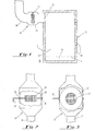
- a shielding means comprising a first generally cylindrically shaped baffle 26 surrounding an internal cylindrical baffle 28. Cool air enters the space between the first baffle 26 and the second baffle 28 and passes in the vicinity of the catalytic converter means 24 and then exits in the space between the second baffle 28 and flue 20.
- Such an installation not only shields the high temperatures of the catalytic converter means 24 from persons in the vicinity thereof, but also provides an additional source of heat transfer to the space being heated by the wood burning stove 10, thus increasing the combustion efficiency of the stove.
- the mounting of the catalytic converter 24 within the flue 20 may be accomplished by situating the catalytic converter means 24 in a metal ring 30 which preferably is formed from stainless steel. At the time the stove is loaded with new or additional fuel, and the door 16 is opened, increased air flow into its combustion chamber 12 occurs and the presence of catalytic converter means 24 may cause an excess back pressure causing smoke to improperly exhaust. In such an instance, it is necessary that the oxidation products bypass the catalytic converter means.
- a handle 32 is provided which projects from the flue 20.
- the handle 32 is connected to the mounting plate 30 which supports the catalytic converter means 24.
- the mounting plate 30 is rotatably mounted within the flue by means of bushings 34 and 36, Rotation of the handle 32 causes rotation of the mounting plate 30 and ultimately of the catalytic converter means 24 so as to permit combustion gases to pass through the flue 20 without passing through the catalytic converter means 24 during those periods when excess back pressure may be encountered such as when the door 16 is open.
- the area 31 in the flue 20 in which rotation occurs has a larger cross-sectional area than the remainder of the flue 20. Without such an arrangement, the converter means 24 would not have sufficient clearance for rotation within the flue 20 unless its cross-sectional area were less than that of the flue.
- FIG. 4A a portion of a flue 20 is shown having an opening 62 therein.
- the opening 62 extends at least 180° about the periphery of the flue.
- Parallel tracks 64 on the internal surface of the flue 20 are provided.
- a catalytic converter means 24 is provided having annular mounting brackets 66 on the top and bottom surfaces thereof, the brackets 66 preferably being formed from stainless steel.
- the brackets 66 are spaced so as to mate with tracks 64 such that the catalytic converter means 24 may be slideably engaged within the flue 20.
- the brackets 66 are joined to a shielding means 68 having a suitable handle 70, such that the catalytic converter means 24 may be selectively placed in the flue 20, with the shield 68 providing a closure to the opening 62.
- the converter means 24 may also be at least partially removed from the flue 20 when new or additional fuel is added to the combustion chamber 12, thus eliminating excess back pressure.
- An additional shielding means similar to that shown at 68 may also be provided which is not associated with a catalytic converter means for closing opening 62 when new or additional fuel is added to the combustion chamber so that smoke does not exit from this opening.
- FIG. 6 still another embodiment of the present invention is disclosed wherein like numerals are utilized to describe features common to the embodiment shown in Figures 1 - 3.
- a wood burning stove 10 is shown having a primary combustion chamber 12 with an ash pan 14.
- a grate 15 provides a support for the location of wood fuel to be combusted within the primary combustion chamber 12.
- Wood fuel is introduced within the primary combustion chamber 12 by means of a door or hatch 16.
- Insulation 18 may be situated within the interior of the combustion chamber 12.
- a catalytic converter means 24 is provided which is located within the primary combustion chamber.
- the insulation 18 is provided to ensure that some of the heat liberated in the combustion chamber 12 is utilized for light off of the catalytic converter means 24.
- the catalytic converter means 24 is retained within a bracket 38, preferably made from stainless steel. Combustion products from the primary combustion chamber 12 exit therefrom by passing through the catalytic converter means 24 and thereafter exiting by means of the flue 20 to the external environment.
- a bypass passageway 40 is provided which communicates with the interior of the combustion chamber 12 of the wood burning stove 10. Access to the bypass passageway 40 is controlled by means of a bypass damper 42 which is rotatable about an axis 44 so as to allow combustion gases to bypass the catalytic converter means 24 during those periods in which an excess back pressure is expected such as when wood fuel is added to the combustion chamber 12.
- Figure 7 discloses a wood burning stove 10 having a primary combustion chamber 12 wherein wood fuel is combusted. Wood fuel is placed in the primary combustion chamber 12 by means of a door or hatch (not shown). Communication between the primary combustion chamber 12 and the ash pan 14 is by way of a grate 15 as shown. Air for combustion enters the primary combustion chamber 12 by means of a primary air inlet 17 and by means of grate 15.
- the primary combustion chamber 12 is preferably insulated to provide sufficient heat for light off of the converter means 24.
- the embodiment shown in Figure 7 also includes a heat exchange chamber 46 interconnected by means of an opening 48 to the primary combustion chamber 12. Situated in or adjacent to the opening 48 is a catalytic converter means 24. Combustion gases from the combustion chamber 12 are directed by means of a flow director or vane 50 to the catalytic converter means and catalyzed combustion gases are then passed through the heat exchanger chamber 46 in the vicinity of a heat exchanger comprising a serpentine series of pipes or tubes 52. The combustion gases are then directed to the flue 20 by means of a communicating passageway 54. Entrance to the communicating passageway 54 is controlled by means of a damper 56 which is rotatable about an axis 58.
- the wood burning stove 10 shown in Figure 7 also includes a bypass passageway 40 controlled by a bypass damper 42 rotatable about an axis 44 whereby combustion gases may be caused by bypass the catalytic converter means 24 when excess back pressure is expected such as during loading of additional fuel.
- a secondary air inlet 60 is provided such that additional oxygen may be provided to the vicinity of the catalytic converter means 24 for sufficient operation thereof.
- the secondary air inlet 60 preferably comprises a tube, one end of which contains apertures 61 in the vicinity of the converter means 24, and the other end terminating in the vicinity of the primary air inlet 17.
- the catalytic converter means 24 employed preferably includes a ceramic monolith having an alumina washcoat applied thereto and coated with precious metal catalysts such as palladium, platinum or alloys of the two in amounts ranging from, for example, 13 grams per cubic foot to 57 grams per cubic foot.
- precious metal catalysts such as palladium, platinum or alloys of the two in amounts ranging from, for example, 13 grams per cubic foot to 57 grams per cubic foot.
- the length, volume, and wall thickness of the catalytic monolith selected as well as the density of the catalytic cells employed are critical for adequate creosote removal without excessive back pressure.
- volume, V in cubic inches, of the converter expressed as a function of cell density, N expressed in terms of cells per square inch, should be at least:
- volume, V of the converter, expressed as a function of cell density, N, should be at least:
- volume, V of the converter, expressed as a function of cell density, N, should be at least:
- the pressure drop through a square cell catalytic converter is defined as: where:
- pressure drop may be considered optimum where K is less than 5. In such a situation, the pressure drop across the catalytic converter means is generally not noticeable. An acceptable pressure drop may still be had where K is greater than or equal to five but less than seven. In such a situation, pressure drop is noticeable, however, there are generally no adverse effects. In the situation where K is greater than or equal to seven but less than 10, a significant pressure drop occurs across the catalytic converter means and the usefulness of a particular catalytic converter means will depend on the particular wood burning stove with which it is utilized. Finally, it is believed that when K is greater than or equal to 10 excessive pressure drop across the converter occurs, such that combustion may not be sustained. As may be seen from the data set forth in Table II, the following catalytic converter means were tested for pressure drop thereacross:
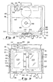
- 110 denotes generally a stove's fire box, comprising of a plane, vertical front wall 113, a pair of spaced, parallel side walls 114 and 115, which project at right angles rearwardly from the front wall 113, and a vertically disposed back wall 116, which extends transversely between the rear edges of the side walls 114 and 115, and parallel to the front wall 113.
- the rectangular firebox 110 is secured centrally on the upper surface of a plane, horizontally disposed bottom plate 117 and is closed at its upper end by a similar plate 118, which is secured adjacent its marginal edges on the fire box adjacent each of its corners on the upper ends of four, similarly shaped metal feet or legs 119, which are designed to support the bottomll7 of the fire box horizontally on the floor of a room or the like.
- the fire box 110 has in the center of its front wall 113 a large rectangular opening 121 (Figs 9 and 10), which is surrounded by a narrow flange 122 that projects laterally from the outer surface of wall 113.
- the opening 121 is adapted to be closed by two, rectangular, similarly-shaped doors 124 and 125, which are hingedly connected as at 126 and 127 to the left and right hand side edges, respectively, of the front wall 113 as shown in Fig. 9.
- These hinge connections 126 and 127 which are conventional and are therefore not described in detail herein, support the doors 124 and 125 so that the inner edges thereof meet and nearly engage along a vertical seam 128 (Fig. 9), when the doors are closed over the opening 121.
- Doors 124 and 125 are manipulated by a pair of knobbed handles 130 and 131 (Figs. 8 and 9), the former of which is a dummy handle that is fixed at its inner end to the lower, right hand corner of door 124 as shown in Fig. 9.
- Handle 131 is rotatably journaled intermediate its ends in an opening 132 formed in the lower left hand corner of door 125 (Fig. 9), and projects at its inner end into the fire box 110 when the doors 124 and 125 are closed.
- Secured at one end to the inner end of handle 131 to project radially therefrom is a small, rectangular plate 134.
- a screw 135 is adjustably threaded into the outer end of plate 134 (Fig. 10) so as to have its head disposed in closely spaced, confronting relation to the stationary fire box wall 113, when the doors 124 and 125 are latched closed as shown in the drawings.
- plate 134 When the plate 134 and adjustable screw 135 are swung by handle 131 into their latching positions (Fig. 10), plate 134 extends downwardly in front of a horizontal plate 138, that is positioned just above and parallel to the bottom plate 117 of the fire box to form part of a liner therefor.
- Plate 138 is fastened adjacent its forward edge to the front wall 113; and adjacent its rear edge it has thereon a downwardly projecting flange portion 139 (Fig. 10) which is supported on plate 117 just forwardly of wall 116.
- the fire box liner also includes a back plate or wall 141 (Fig 10), which is secured along its lower edge to the rear edge of the liner plate 138, and the lower portion of which projects upwardly and parallel to the rear wall 116 of the fire box. Intermediate its ends plate 141 is bent slightly as at 142 so that its upper portion is inclined slightly to the vertical, and away from the rear wall 116 of the fire box. This inclined, upper portion of the liner plate 141 has therein a large, rectangular bypass opening 143 which registers with an exhaust opening 144 that is formed in the upper end of the rear fire box wall 116 for a purpose noted hereinafter.
- Opening 143 is adapted to be closed by a large, rectangular damper plate 146, which has its lower edge mounted for pivotal movement in an angle bracket 147, that is secured to the inside surface of plate 141 adjacent to the lower edge of opening 143.
- Plate 146 is pivotal between the legs of a generally U-shaped bracket 148, the marginal side of which are fastened to the inside surface of the liner plate 141 adjacent opposite sides of opening 143.
- the back or inside surface of damper plate 146 rests upon the inner end of a push rod 150, which slides adjacent its inner end in an opening in a support plate 151, which is fastened to, and projects upwardly from, bracket 148.
- Adjacent its outer end rod 150 projects slidably through an opening in a stationary baffle 152 on the upper edge of wall 113, and into engagement with the inside of the door 125 when the latter is closed.
- the weight of the inclined damper plate 146 urges the push rod 150 toward the left in Fig. 10 until the plate 146 is swung from its closed, full line position to its open or broken line position as shown in Fig. 10, wherein the upper edge of plate 146 comes to rest against the support plate 151.
- the door 125 is closed, it re-engages the push rod 150 and forces it and plate 146 back to their full line positions as shown in Fig. 10, thus once again closing the bypass opening 143.
- a rectangular housing 155 Secured on top of the fire box cover plate 118 substantially centrally thereof is a rectangular housing 155, the upper end of which is sealed by a large flat cover plate 157 which is similar in configuration to, but slightly smaller than, plate 118.
- the interior of housing 155 defines an exhaust chamber 158, which communicates through a large, rectangular opening 159 (Fig. 10), in plate 118 with the space formed in the upper end of the fire box between the bypass opening 143 and the exhaust opening 144 in wall 116.
- a rigid plate or shelf 161 Secured along one edge of the inside of the vertical portion of the liner plate 141, and projecting horizontally therefrom into the center of the fire box above and in spaced, parallel relation to the bottom plate 138 of the liner, is a rigid plate or shelf 161, which can be used to support thereon burning embers for banking a fire in the box no as noted hereinafter.
- a plurality of spaced, parallel metal bars 162 Secured in opposite ends in the opposed side walls of the fire box, and extending transversely therebetween in a plane containing the shelf 161, is a plurality of spaced, parallel metal bars 162, which form supports for a conventional grate (not illustrated), which may be removably placed in a fire box 110 for holding kindling, fire wood, etc. in a known manner.
- a relatively shallow, rectangular ash pan 164 Removably mounted on the liner plate 138, and extending at its rear and beneath the support rods 162 and the shelf 161, is a relatively shallow, rectangular ash pan 164.
- the forward, vertically disposed wall 165 of the pan 164 is spaced horizontally from the front wall 113 of the fire box, and has thereon a forwardly projecting lip or flange 116 which overlies the door latching plate 134, and which provides a handle portion for moving the pan 164 into and out of the fire box through its front doors 124 and 125. When these doors are closed (Fig.
- the forward edge of the flange 166 is spaced slightly rearwardly from the inside surfaces of the doors to allow air for combustion to enter the combustion chamber above pan 164 from the space between plates 117 and 138, as noted hereinafter. Air from this latter space is also permitted to enter the combustion chamber through a plurality of spaced openings 167 which are formed in the front wall 165 of the pan.
- the primary source of air for supporting combustion in the fire box 110 is a rectangular opening 171 (Fig. 10), which is formed in the base plate 117 adjacent to its rear edge, and inwardly from the flange 139 on the liner plate 138.
- the quantity of air admitted through this opening is controlled by a damper plate 172, which is supported by a bracket 173 for sliding movement against the underside of plate 117.
- a pair of lugs 174, which project from the bottom of plate 172 adjacent to its forward end, are adjustably attached to the threaded end of a horizontal operating rod 175, which is slidably supported intermediate its ends by bracket 176 which projects from the underside plate 117.
- a knob 177 on the outer end of rod 175 can be used manually to shift the damper 172 back and forth to cover or uncover the opening 171 to varying degrees, thereby to control the amount of primary combustion air that is admitted to the fire box.
- a steel ring or sleeve 181 Secured intermediate its ends in a circular opening, which is formed in the fire box cover plate 118 medially of its sides and slightly to the left (Fig. 10), or forwardly of its centerline, is a steel ring or sleeve 181.
- a steel ring or sleeve 181 Removably mounted in the bore sleeve 181 is the cylindrically-shaped catalytic converter element 182.
- the outside diameter of element 182 is slightly less than the inside diameter of sleeve 181 so that the element can be readily inserted into, and withdrawn from the bore of the sleeve.
- Element 182 is seated at its lower end on an elongate supporting pin 184, opposite ends which are removably seated in registering openings formed in the annular wall of sleeve 181 adjacent to its lower end, so that the pin 184 extends substantially diametrally across the center of the sleeve.
- the sleeve 181 and the enclosed converter element extend at their upper ends part way into the exhaust chamber 158 in the housing 155, and at their lower ends extend into the upper end of the combustion chamber in the fire box 110.
- a stainless steel plate 185 Welded or otherwise secured to the inside surface of the exhaust chamber cover plate 157 to overlie the upper ends of sleeve 181 and its converter element 182 is a stainless steel plate 185.
- a circular opening 186 in the center of plate 185 registers coaxially with the sleeve 181 and element 182, and also with a circular opening 187 in the plate 157.
- a transparent, disc-shaped window or sight glass 188 is secured in the opening 187 to register with the center of the converter element 182, and to provide means for observing the element during operation of the stove.
- this duct 191 is secured at its inner end around the opening 144 in plate 116, and extends intermediate its ends through a registering opening formed in the back 193 of a generally U-shaped radiation shield which surrounds the rear portion of the fire box 110 between plates 117 and 118.
- This shield includes two, spaced, parallel side portions or arms 194 and 195, which project from section 193 forwardly to be disposed in spaced, parallel, overlapping relation to slightly more than the rear halves of the side walls 114 and.115 of the fire box.
- a conventional electric blower 196 which is mounted at the exterior of the radiation shield (Fig. 10), has its discharge end secured by a plate 197 over opening 198, which is formed in the back portion 193 of the shield in communication with the narrow space which is formed between the shield and the rear portion of the fire box.
- the shield 193, 194, 195 and the associated blower 196 perform the functions of preventing the fire box side walls 114 and 115 from over heating, thereby obviating the need to employ a fire brick lining in the fire box, and also serving to direct heated air from the space between the shield and the fire box out of the vertical openings formed between the forward edges of the shield and the fire box, when the stove and fan 196 are in use. Even when the fan is not in use the shield blocks direct radiation from the back and side walls of fire box 110 allowing the stove to be safely positioned closer to combustible walls.
- the doors 124 and 125 have therein large, central, rectangular openings 201 and 202 respectively.
- Each of the openings 201 and 202 is closed by a pair of spaced, parallel, vertically disposed panes 203 and 204 of medium and high temperature glass, respectively. Two of these panes are shown by way of example in Fig. 11. Since the manner in which the way the two panes are mounted in each door 124 and 125 is similar, only the construction of door 124 will be described in detail herein.
- 206 denotes generally a rectangular frame which is fastened to the inside of the door 124 around its opening 201.
- This frame also has therethrough a rectangular opening 207 which registers with, and is similar in configuration to, the opening 201 in the door.
- the panes 203 and 204 are secured in frame 206 to extend transversely-between the opening 201 and 207 in spaced, parallel relation to each other.
- the outer pane 203 is sealingly secured by conventional gasket material along three of its edges, namely its upper edge (as at 208) and along its two side edges, against the inside of door 124 around its opening 201.
- pane 204 has its two vertical side edges and its lower edge secured, as at 211, by gasket material against the inside surface of the frame 206 around its opening 207, so that its upper edge is spaced as at 212 slightly beneath the confronting surface of frame 206.
- panes 203 and 204 are mounted in each door 124 and 125, when the stove is in operation a secondary supply of air for combustion enters the interior of the fire box through its doors 124 and 125 by passing through the gap 209 along the bottom of the outer pane 203, as indicated by the arrows in Fig. 11, then upwardly between the panes 203 and 204, and then through the gap 212 and out of the opening 207 in frame 206 to the combustion chamber adjacent its upper end. Assuming that the stove is in operation, primary air will also be entering the interior of the fire box at this time from beneath the liner plate 138, passing upwardly as shown by the arrows in Fig.
- the inner pane operates at a higher temperature due to reflected radiation from the outer pane.
- the higher temperature reduces condensation.
- the secondary air flow draws any flow of smoke away from the upper portion of the window.
- FIG 12 which is similar to Fig. 11, illustrates a modified manner of mounting the two panes 203 and 204 in doors 124 and 125 to permit a secondary supply of air therethrough.
- each of the panes 203 and 204 has its vertical side edges and its lower edge secured by gasket material as in 215 against the inside frame 206, thereby forming a gap 216 in the frame 206 over the upper edges of the two panes 203 and 204 in each door so that the secondary air supply enters through the doors 124 and 125 over the upper edges of the panes.
- the primary air still enters the fire box over the forward edge of the lip 166 on the ash pan 164, so that the incoming primary air tends to wash or clean the inside surfaces to the inner panes 204.
- handle 131 may be manupilated by rotating it counterclockwise from its position as shown in Fig. 9, thereby swinging its latching screw 135 out of registry with the bottom of wall 113, and thus permitting both doors 124 and 125 to be swung open about their respective hinges 126 and 127.
- a conventional grate (not illustrated) can then be placed on top of supporting rods 162, together with a supply of fuel (for example wood).
- the damper 172 is then opened at least partially; and assuming that the converter element 182 is already in the holder 181, the fire can be started and the doors 124 and 125 once again may be closed.
- the damper plate 146 swings downwardly to its broken line position in Fig.
- the present invention provides a relatively simple and inexpensive means for effecting substantially complete and thorough combustion of all combustible by-products of the fuel which is burned in the main combustion chamber of applicant's novel stove.
- combustion air from two different sources, (i.e. both from the bottom and from the top of the fire box) it is possible better to maintain the quantity of oxygen necessary to support combustion both in the main combustion chamber of the fire box, and in the vicinity of the converter element 182.
- the automatically operating damper control rod 150 provides a simple means for eliminating any undesirable flashback or discharge of flame and gas out of the front of the stove whenever its doors 124 and 125 are open.
Applications Claiming Priority (4)
| Application Number | Priority Date | Filing Date | Title |
|---|---|---|---|
| US06/136,687 US4494525A (en) | 1980-04-02 | 1980-04-02 | Stove with catalytic converter |
| US17315580A | 1980-07-28 | 1980-07-28 | |
| US173155 | 1980-07-28 | ||
| US136687 | 2008-09-25 |
Publications (3)
| Publication Number | Publication Date |
|---|---|
| EP0037281A2 true EP0037281A2 (de) | 1981-10-07 |
| EP0037281A3 EP0037281A3 (en) | 1981-12-23 |
| EP0037281B1 EP0037281B1 (de) | 1985-09-11 |
Family
ID=26834547
Family Applications (1)
| Application Number | Title | Priority Date | Filing Date |
|---|---|---|---|
| EP81301389A Expired EP0037281B1 (de) | 1980-04-02 | 1981-03-31 | Ofen zum Verbrennen festen Brennstoffs und katalytischer Konverter |
Country Status (3)
| Country | Link |
|---|---|
| EP (1) | EP0037281B1 (de) |
| CA (1) | CA1178031A (de) |
| DE (1) | DE3172190D1 (de) |
Cited By (17)
| Publication number | Priority date | Publication date | Assignee | Title |
|---|---|---|---|---|
| WO1982001931A1 (en) * | 1980-12-02 | 1982-06-10 | Sorensen Jens C | Central heating boiler with a second burner |
| EP0072391A1 (de) * | 1981-08-17 | 1983-02-23 | Atlanta Stove Works, Inc. | Ofen mit katalytischem Nachbrenner und Bypass |
| EP0087259A1 (de) * | 1982-02-22 | 1983-08-31 | Corning Glass Works | Verbrennungsvorrichtung für eine Festbrennstoffheizanlage |
| EP0087878A1 (de) * | 1982-02-22 | 1983-09-07 | Corning Glass Works | Ofen zum Verbrennen von Holz |
| FR2527746A1 (fr) * | 1982-06-01 | 1983-12-02 | Vermont Castings | Appareil de chauffage brulant un combustible |
| DE3404237A1 (de) * | 1984-02-07 | 1985-08-08 | Agro Stahlsonderbau | Verbrennungsofen |
| US4582044A (en) * | 1984-01-19 | 1986-04-15 | Vermont Castings, Inc. | Clean burning exterior retrofit system for solid fuel heating appliances |
| US4646712A (en) * | 1983-11-28 | 1987-03-03 | Vermont Castings, Inc. | Solid fuel heating appliances |
| US4683868A (en) * | 1986-04-09 | 1987-08-04 | Vermont Castins, Inc. | Wood burning stove having glass cleaning system |
| US5816237A (en) * | 1993-02-23 | 1998-10-06 | Superior Fireplace Company | Low emission fireplace |
| DE102007027136A1 (de) * | 2007-06-13 | 2008-12-18 | Earthfly Holding Gmbh | Vorrichtung zur Reinigung der Abgase einer Hausbrandstelle mit Abgaskamin |
| NL2001058C2 (nl) * | 2007-12-05 | 2009-06-08 | D & J Holding B V | Haard en werkwijze voor het reinigen van verbrandingsgassen van een haard. |
| ITUD20110023A1 (it) * | 2011-02-18 | 2012-08-19 | Palazzetti Lelio Spa | Dispositivo di trattamento catalitico di fumi di combustione per una stufa a biomassa, particolarmente a legna |
| WO2013159782A1 (en) * | 2012-04-27 | 2013-10-31 | Skamol A/S | Catalytic unit for solid fuel burning stoves |
| EP2910854A3 (de) * | 2014-02-19 | 2016-01-20 | Karl Stefan Riener | Rauchgasklappeneinrichtung |
| IT201800006316A1 (it) * | 2018-06-14 | 2019-12-14 | Stufa pirolitica ad accumulo perfezionata | |
| GB2623332A (en) * | 2022-10-12 | 2024-04-17 | Stovax Ltd | Solid fuel appliance |
Families Citing this family (1)
| Publication number | Priority date | Publication date | Assignee | Title |
|---|---|---|---|---|
| AT399931B (de) * | 1992-09-21 | 1995-08-25 | Vaillant Gmbh | Gebläseunterstütztes heizgerät |
Citations (2)
| Publication number | Priority date | Publication date | Assignee | Title |
|---|---|---|---|---|
| US3112184A (en) * | 1958-09-08 | 1963-11-26 | Corning Glass Works | Method of making ceramic articles |
| US3790654A (en) * | 1971-11-09 | 1974-02-05 | Corning Glass Works | Extrusion method for forming thinwalled honeycomb structures |
-
1981
- 1981-03-31 EP EP81301389A patent/EP0037281B1/de not_active Expired
- 1981-03-31 DE DE8181301389T patent/DE3172190D1/de not_active Expired
- 1981-04-02 CA CA000374510A patent/CA1178031A/en not_active Expired
Patent Citations (2)
| Publication number | Priority date | Publication date | Assignee | Title |
|---|---|---|---|---|
| US3112184A (en) * | 1958-09-08 | 1963-11-26 | Corning Glass Works | Method of making ceramic articles |
| US3790654A (en) * | 1971-11-09 | 1974-02-05 | Corning Glass Works | Extrusion method for forming thinwalled honeycomb structures |
Cited By (22)
| Publication number | Priority date | Publication date | Assignee | Title |
|---|---|---|---|---|
| WO1982001931A1 (en) * | 1980-12-02 | 1982-06-10 | Sorensen Jens C | Central heating boiler with a second burner |
| EP0072391A1 (de) * | 1981-08-17 | 1983-02-23 | Atlanta Stove Works, Inc. | Ofen mit katalytischem Nachbrenner und Bypass |
| EP0087259A1 (de) * | 1982-02-22 | 1983-08-31 | Corning Glass Works | Verbrennungsvorrichtung für eine Festbrennstoffheizanlage |
| EP0087878A1 (de) * | 1982-02-22 | 1983-09-07 | Corning Glass Works | Ofen zum Verbrennen von Holz |
| FR2527746A1 (fr) * | 1982-06-01 | 1983-12-02 | Vermont Castings | Appareil de chauffage brulant un combustible |
| GB2121162A (en) * | 1982-06-01 | 1983-12-14 | Vermont Castings | Solid fuel stoves |
| US4487195A (en) * | 1982-06-01 | 1984-12-11 | Vermont Castings, Inc. | Fuel burning heating apparatus |
| US4646712A (en) * | 1983-11-28 | 1987-03-03 | Vermont Castings, Inc. | Solid fuel heating appliances |
| US4582044A (en) * | 1984-01-19 | 1986-04-15 | Vermont Castings, Inc. | Clean burning exterior retrofit system for solid fuel heating appliances |
| DE3404237A1 (de) * | 1984-02-07 | 1985-08-08 | Agro Stahlsonderbau | Verbrennungsofen |
| US4683868A (en) * | 1986-04-09 | 1987-08-04 | Vermont Castins, Inc. | Wood burning stove having glass cleaning system |
| FR2597196A1 (fr) * | 1986-04-09 | 1987-10-16 | Vermont Castings | Poele a combustibles solides notamment poele a bois equipe d'un dispositif de nettoyage des parois transparentes |
| BE1001313A3 (fr) * | 1986-04-09 | 1989-09-26 | Vermont Castings | Appareil de chauffage a combustible solide. |
| US5816237A (en) * | 1993-02-23 | 1998-10-06 | Superior Fireplace Company | Low emission fireplace |
| DE102007027136A1 (de) * | 2007-06-13 | 2008-12-18 | Earthfly Holding Gmbh | Vorrichtung zur Reinigung der Abgase einer Hausbrandstelle mit Abgaskamin |
| NL2001058C2 (nl) * | 2007-12-05 | 2009-06-08 | D & J Holding B V | Haard en werkwijze voor het reinigen van verbrandingsgassen van een haard. |
| WO2009072875A1 (en) * | 2007-12-05 | 2009-06-11 | D+J Holding B.V. | Fireplace and method for cleaning combustion gases from a fireplace |
| ITUD20110023A1 (it) * | 2011-02-18 | 2012-08-19 | Palazzetti Lelio Spa | Dispositivo di trattamento catalitico di fumi di combustione per una stufa a biomassa, particolarmente a legna |
| WO2013159782A1 (en) * | 2012-04-27 | 2013-10-31 | Skamol A/S | Catalytic unit for solid fuel burning stoves |
| EP2910854A3 (de) * | 2014-02-19 | 2016-01-20 | Karl Stefan Riener | Rauchgasklappeneinrichtung |
| IT201800006316A1 (it) * | 2018-06-14 | 2019-12-14 | Stufa pirolitica ad accumulo perfezionata | |
| GB2623332A (en) * | 2022-10-12 | 2024-04-17 | Stovax Ltd | Solid fuel appliance |
Also Published As
| Publication number | Publication date |
|---|---|
| CA1178031A (en) | 1984-11-20 |
| EP0037281A3 (en) | 1981-12-23 |
| DE3172190D1 (en) | 1985-10-17 |
| EP0037281B1 (de) | 1985-09-11 |
Similar Documents
| Publication | Publication Date | Title |
|---|---|---|
| US4494525A (en) | Stove with catalytic converter | |
| EP0037281B1 (de) | Ofen zum Verbrennen festen Brennstoffs und katalytischer Konverter | |
| US4373452A (en) | Wood burning stove | |
| US4330503A (en) | Wood burning stove | |
| US6425390B2 (en) | Unvented heating appliance having system for reducing undesirable combustion products | |
| US4856491A (en) | High efficiency solid fuel burning stove | |
| US4363785A (en) | Wood stove having catalytic converter | |
| US4112913A (en) | Free standing heating unit | |
| US4074679A (en) | Fireplace stove | |
| EP0072391A1 (de) | Ofen mit katalytischem Nachbrenner und Bypass | |
| US4479921A (en) | Solid fuel heating appliance and combustor apparatus therefor | |
| US4844051A (en) | Fuel burning appliance incorporating catalytic combustor | |
| US4630553A (en) | Dual stage combustion furnace | |
| US4345528A (en) | Wood burning stove | |
| USRE33077E (en) | Wood burning stove | |
| US7082942B2 (en) | Wood burner with improved emissions | |
| JP2678253B2 (ja) | ゴミ焼却炉 | |
| US5050579A (en) | Combustor assembly for a fuel-burning room heater | |
| CA1167721A (en) | Space heating stove | |
| US4719899A (en) | Depot for granular carbonaceous fuel and method employing the same to provide high efficiency fires for charbroiling and the like | |
| US4502462A (en) | Wood stove | |
| US4506653A (en) | Combustion method and apparatus | |
| EP3306200B1 (de) | Konvektionsofen | |
| US4690126A (en) | Catalytic combustion assembly for wood-burning stove | |
| US5201307A (en) | Insulated firebox for swimming pool or spa heaters for reduction of smoke or odor |
Legal Events
| Date | Code | Title | Description |
|---|---|---|---|
| PUAI | Public reference made under article 153(3) epc to a published international application that has entered the european phase |
Free format text: ORIGINAL CODE: 0009012 |
|
| AK | Designated contracting states |
Designated state(s): BE DE FR GB SE |
|
| PUAL | Search report despatched |
Free format text: ORIGINAL CODE: 0009013 |
|
| AK | Designated contracting states |
Designated state(s): BE DE FR GB SE |
|
| RHK1 | Main classification (correction) |
Ipc: F23J 15/00 |
|
| 17P | Request for examination filed |
Effective date: 19820522 |
|
| RAP1 | Party data changed (applicant data changed or rights of an application transferred) |
Owner name: CORNING GLASS WORKS |
|
| GRAA | (expected) grant |
Free format text: ORIGINAL CODE: 0009210 |
|
| AK | Designated contracting states |
Designated state(s): BE DE FR GB SE |
|
| REF | Corresponds to: |
Ref document number: 3172190 Country of ref document: DE Date of ref document: 19851017 |
|
| ET | Fr: translation filed | ||
| PLBE | No opposition filed within time limit |
Free format text: ORIGINAL CODE: 0009261 |
|
| STAA | Information on the status of an ep patent application or granted ep patent |
Free format text: STATUS: NO OPPOSITION FILED WITHIN TIME LIMIT |
|
| 26N | No opposition filed | ||
| PGFP | Annual fee paid to national office [announced via postgrant information from national office to epo] |
Ref country code: GB Payment date: 19910215 Year of fee payment: 11 |
|
| PGFP | Annual fee paid to national office [announced via postgrant information from national office to epo] |
Ref country code: FR Payment date: 19910321 Year of fee payment: 11 |
|
| PGFP | Annual fee paid to national office [announced via postgrant information from national office to epo] |
Ref country code: DE Payment date: 19910327 Year of fee payment: 11 |
|
| PGFP | Annual fee paid to national office [announced via postgrant information from national office to epo] |
Ref country code: SE Payment date: 19910328 Year of fee payment: 11 |
|
| PGFP | Annual fee paid to national office [announced via postgrant information from national office to epo] |
Ref country code: BE Payment date: 19910626 Year of fee payment: 11 |
|
| PG25 | Lapsed in a contracting state [announced via postgrant information from national office to epo] |
Ref country code: GB Effective date: 19920331 Ref country code: BE Effective date: 19920331 |
|
| PG25 | Lapsed in a contracting state [announced via postgrant information from national office to epo] |
Ref country code: SE Effective date: 19920401 |
|
| BERE | Be: lapsed |
Owner name: CORNING GLASS WORKS Effective date: 19920331 |
|
| GBPC | Gb: european patent ceased through non-payment of renewal fee | ||
| PG25 | Lapsed in a contracting state [announced via postgrant information from national office to epo] |
Ref country code: FR Effective date: 19921130 |
|
| PG25 | Lapsed in a contracting state [announced via postgrant information from national office to epo] |
Ref country code: DE Effective date: 19921201 |
|
| REG | Reference to a national code |
Ref country code: FR Ref legal event code: ST |
|
| EUG | Se: european patent has lapsed |
Ref document number: 81301389.3 Effective date: 19921108 |