EP0036311A1 - Mechanical feed-up of web material on a recoiler - Google Patents
Mechanical feed-up of web material on a recoiler Download PDFInfo
- Publication number
- EP0036311A1 EP0036311A1 EP81301062A EP81301062A EP0036311A1 EP 0036311 A1 EP0036311 A1 EP 0036311A1 EP 81301062 A EP81301062 A EP 81301062A EP 81301062 A EP81301062 A EP 81301062A EP 0036311 A1 EP0036311 A1 EP 0036311A1
- Authority
- EP
- European Patent Office
- Prior art keywords
- recoiler
- slitting
- web
- uncoiler
- slitter head
- Prior art date
- Legal status (The legal status is an assumption and is not a legal conclusion. Google has not performed a legal analysis and makes no representation as to the accuracy of the status listed.)
- Withdrawn
Links
Images
Classifications
-
- B—PERFORMING OPERATIONS; TRANSPORTING
- B65—CONVEYING; PACKING; STORING; HANDLING THIN OR FILAMENTARY MATERIAL
- B65H—HANDLING THIN OR FILAMENTARY MATERIAL, e.g. SHEETS, WEBS, CABLES
- B65H19/00—Changing the web roll
- B65H19/22—Changing the web roll in winding mechanisms or in connection with winding operations
- B65H19/28—Attaching the leading end of the web to the replacement web-roll core or spindle
-
- B—PERFORMING OPERATIONS; TRANSPORTING
- B21—MECHANICAL METAL-WORKING WITHOUT ESSENTIALLY REMOVING MATERIAL; PUNCHING METAL
- B21C—MANUFACTURE OF METAL SHEETS, WIRE, RODS, TUBES OR PROFILES, OTHERWISE THAN BY ROLLING; AUXILIARY OPERATIONS USED IN CONNECTION WITH METAL-WORKING WITHOUT ESSENTIALLY REMOVING MATERIAL
- B21C47/00—Winding-up, coiling or winding-off metal wire, metal band or other flexible metal material characterised by features relevant to metal processing only
- B21C47/006—Winding-up, coiling or winding-off metal wire, metal band or other flexible metal material characterised by features relevant to metal processing only winding-up or winding-off several parallel metal bands
-
- B—PERFORMING OPERATIONS; TRANSPORTING
- B65—CONVEYING; PACKING; STORING; HANDLING THIN OR FILAMENTARY MATERIAL
- B65H—HANDLING THIN OR FILAMENTARY MATERIAL, e.g. SHEETS, WEBS, CABLES
- B65H35/00—Delivering articles from cutting or line-perforating machines; Article or web delivery apparatus incorporating cutting or line-perforating devices, e.g. adhesive tape dispensers
- B65H35/02—Delivering articles from cutting or line-perforating machines; Article or web delivery apparatus incorporating cutting or line-perforating devices, e.g. adhesive tape dispensers from or with longitudinal slitters or perforators
-
- B—PERFORMING OPERATIONS; TRANSPORTING
- B65—CONVEYING; PACKING; STORING; HANDLING THIN OR FILAMENTARY MATERIAL
- B65H—HANDLING THIN OR FILAMENTARY MATERIAL, e.g. SHEETS, WEBS, CABLES
- B65H2301/00—Handling processes for sheets or webs
- B65H2301/40—Type of handling process
- B65H2301/41—Winding, unwinding
- B65H2301/414—Winding
- B65H2301/4148—Winding slitting
-
- B—PERFORMING OPERATIONS; TRANSPORTING
- B65—CONVEYING; PACKING; STORING; HANDLING THIN OR FILAMENTARY MATERIAL
- B65H—HANDLING THIN OR FILAMENTARY MATERIAL, e.g. SHEETS, WEBS, CABLES
- B65H2301/00—Handling processes for sheets or webs
- B65H2301/50—Auxiliary process performed during handling process
- B65H2301/51—Modifying a characteristic of handled material
- B65H2301/513—Modifying electric properties
- B65H2301/5133—Removing electrostatic charge
Definitions
- the present invention relates to slitting lines in which an elongate web of material, such as sheet metal in coil form, is unwound from an uncoiler, slit into multiple strips by rotary slitting knives and coiled on a recoiler.
- the invention pertains to a method of and apparatus for conveniently feeding-up the web material by transferring its leading end from the uncoiler, through the slitter head that contains the slitting knives to the recoiler mandrel for attachment thereto.
- the present invention provides a means for significantly reducing the labor and time required for the feed-up operation in a sheet metal slitting line by replacing much of the manual effort heretofore required by mechanical effort.
- the result is a feed-up operation that is less hazardous to the workman and more efficient in terms of the costs heretofore attributed to this operation.
- a method of feeding web material from a coil on an uncoiler to a recoiler through a slitter head containing rotary slitting knives comprising the steps of moving said slitter head to a position closely adjacent said uncoiler; unwinding said web material from said uncoiler to place the leading end thereof at the nip of said slitting knives; engaging said web leading end by said slitting knives; moving said slitter head to a position closely adjacent said recoiler; operating said knives to move the leading end of said web into engagement with said recoiler; and attaching said web leading end to said recoiler.
- the invention also provides a web slitting line containing an uncoiler for carrying a coil of web material, a recoiler spaced from said uncoiler, a slitter head positioned intermediate said uncoiler and said recoiler and containing at least one pair of rotary slitting knives for slitting said web into a plurality of strips, and means for moving said slitter head from a position closely adjacent said uncoiler to a position closely adjacent said recoiler.
- the invention further provides a slitter head comprising a frame; opposed pairs of rotary knives mounted on said frame for slitting web material passed therebetween; a pair of opposed pinch rolls on said frame forwardly adjacent said rotary knives adapted to drive said web material thereto; and a peeling blade pivotally attached to said frame having a free end adapted to strip the outermost wrap of web material from said uncoiler when said frame is moved to a position adjacent thereto.
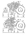
- a slitting line 10 consisting of an uncoiler 12, a recoiler 14 longitudinally spaced from the uncoiler and a slitter mechanism 16 interposed therebetween.
- the slitter mechanism includes a slitter head 18 containing pinch rolls 20 and pairs of opposed rotary slitting knives 22 and knock-down rolls 24 for slitting an elongate sheet metal web.
- the slitting knives 22 are typically notched as at 26 ( Figure 4) to slit the web in the manner described in detail in United States Patent No. 4,155,238, which manner of slitting will be more fully described hereinafter to an extent sufficient for an understanding of the present invention.
- a coil 28 of wound sheet metal is positioned on the mandrel 30 of uncoiler 12 and arranged to be conducted through the slitting head 18 where the web indicated as 32 in Figure 6 is continuously slit to produce parting lines 34 defining multiple strips 36 prior to winding on the recoiler 14.
- the uncoiler mandrel 30, as shown, is rotatably driven by a motor 38 through appropriate reduction gearing 40, all as is well known in the art.
- the recoiler 14, also of well-known construction comprises a horizontally disposed mandrel 42 that is driven by drive motor 44 through reduction gearing 46.
- the recoiler mandrel 42 is provided on its external surface with a gripper device 48 that includes an elongate slot 50 extending parallel to the mandrel axis and a gripper shaft 52 operated by a tool-receiving head 54.
- the shaft 52 contains a chordal flat that is caused, upon rotation of the shaft, to engage and hold the leading end 58 of web 32 fast to the mandrel 42.
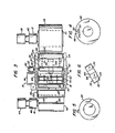
- the slitting head 18 comprises an open, generally rectangular frame structure having a bottom 58, a top 60 and opposed side members 62 and 64.
- the side members 62 and 64 each contain a vertically elongate opening 66 defining a guideway for slidable bearing blocks 68 that journal the opposite ends of drive shafts 70 and 72 that carry the slitting knives 22.
- the shafts 70 and 72 are operatively connected at one end to an appropriate drive 74 mounted on the adjacent side member.
- Fluid-operated cylinders 76 attached over the top of the respective side members 62 and 64 are operative through piston rods 78 for adjusting the spacing between the drive shafts 70 and 72 and thereby between the cutting edges of the opposed knives 22 in each pair.
- the frame side members 62 and 64 each attach oppositely spaced extension plates 80 and 82, the former pair extending rearwardly of the slitting head 18 and the latter extending forwardly thereof.
- Extension plates 80 each contain an elongate opening 84 for slidably mounting bearing blocks 86 that journal the ends of pinch rolls 20.
- the pinch rolls 20 may be selectively driven by appropriate gearing indicated generally at 90 from the slitter drive 74.
- Quick acting cylinders 92 are positioned atop the plates 80 and connect with the upper bearing blocks 86 to raise the upper pinch roll upon demand.
- a peeler 94 is pivotally mounted to the slitting head and extends transversely across the path traversed by the web 32 prior to its entering the slitting head 18.
- the peeler 94 in the described arrangement is formed by an elongate plate 96 having a knife edge 98 at its free end and gussets 99 at opposite sides, which gussets contain slightly oversized openings to permit the plate to be pivotally collared about the shaft of the lower pinch roll.
- a stop bar 100 extends between the extension plates 80 and serves to limit the extent of pivotal movement of the peeler downwardly to the position shown in Figure 2.
- Extension plates 82 which extend forwardly from each side member of the frame of slitting head 18 contain vertically spaced openings to receive bearings for journalling the shafts of the knock-down rolls 24.
- the knock-down rolls are driven by appropriate drive means, indicated generally as 101 in Figure 3, off the slitter drive 74.
- the drive means 101 includes an overrunning clutch (not shown) whereby the knock-down rolls 24 are permitted to rotate freely when movement of the web 32 is undertaken by the recoiler 14 as hereinafter more fully explained.
- the extension plates 82 also mount a web guide 102 comprising oppositely spaced formed plates 104 and 106 that serve to guide the leading end of web 32 into the gripper slot 50 on the recoiler mandrel 42.
- the plates 104 and 106 are arranged to conform generally to the external surface of the mandrel 42 and a bearing pad 108 is associated with lower plate 106 to permit the guide 102 to bear on the mandrel without gouging or otherwise damaging the surface thereof.
- a press roll 110 driven by motor 112 extends forwardly of the upper portion of the slitting head 18.
- the roll 110 and motor 112 are mounted from oppositely spaced arms 114 attached to the slitting head frame.
- the ends of the press roll 110 are journalled in bearing blocks 116 that are slidable in ways 118 and that are biased downwardly by springs 120. Stops 121 serve to retain the bearing blocks 116 in the ways 118.
- the slitting head 18 is supported for pivotal movement between the uncoiler 12 and recoiler 14 upon a pedestal 122 that contains pivot shaft 124.
- a pivot support 126 having arms 128 that straddle the pedestal 122 and an attachment key 130 extending between and uniting the arms serves to attach the slitting head.
- key 130 is adapted to be slidably received in a keyway 132 formed in the bottom 58 of the slitting head thereby facilitating removal by replacement of heads having various slitter configurations.
- Set screws (not shown) or other appropriate locking mechanism serve to attach the slitting head to the key.
- Pivotal movement is imparted to the assembly by a fluid operated cylinder 134 whose piston rod 136 is pin-connected to a clevis on the pivot support 126.
- the extent of pivotal movement of the slitter head support can be limited in the rearward direction by provision of a limit plate 138 that extends between the arms 128 and that bears on the forward face 140 of the pedestal 122.
- the hereindescribed apparatus is adapted to mechanically transfer the leading end of the web 32 of sheet metal being slit from the uncoiler 12 to the recoiler 14 for attachment to the recoiler mandrel 42 as part of the feed-up operation that is a necessary prerequisite to any continuous slitting operation.
- This function is accomplished as follows. With a coil 28 of sheet metal web material mounted on the mandrel 30 of uncoiler 12 fluid cylinder 134 is actuated to move the slitting head 18 rearwardly until stopped by abutment of the limit plate 138 with the forward face 140 of the pedestal 122, as shown in Figure 1.
- This action places the free edge of the peeler 94 in bearing engagement on the surface of the coil 28 just forwardly of the leading end of the outermost wrap and the press roll 110 in engagement with the coil just rearwardly thereof.
- the slitter mechanism drive 74 including the press roll motor 112 and the drive motor 38 of the uncoiler are actuated thereby causing the leading end of the web to unwrap from the coil and move across the upper surface of the peeler plate 96 toward the nip of the pinch rolls 88.
- cylinders 92 are actuated to momentarily raise the upper roll permitting the web to pass between the rolls.
- the web 32 is extended through the opening between the guide plates 104, 106 with an additional assist from the driving force of the knock-down rolls 24 until its leading end 58 extends sufficiently beyond the end of the opening between the plates 104, 106 to permit insertion of the web into the gripper mechanism 48 in the mandrel 42 of recoiler 14.
- the fluid cylinder 134 will be continuously operated to slowly pivot the slitter head assembly rearwardly as the coil on the recoiler mandrel is built up.
Abstract
The slitting head 18 in a slitting line for severing sheet metal web material 28 into strips is utilized to transfer the leading end of the web material from the uncoiler 30 to the recoiler for attachment thereto during the feed-up operation. The slitting head 18 is mounted on a swing arm 126 pivoted on a shaft 124. This arrangement enables the operation of setting up the slitting head and recoiler for a new coil of web material to be performed more safely in reduced time and with less effort and manpower.
Description
- The present invention relates to slitting lines in which an elongate web of material, such as sheet metal in coil form, is unwound from an uncoiler, slit into multiple strips by rotary slitting knives and coiled on a recoiler. In particular, the invention pertains to a method of and apparatus for conveniently feeding-up the web material by transferring its leading end from the uncoiler, through the slitter head that contains the slitting knives to the recoiler mandrel for attachment thereto.
- In the feed-up of a conventional slitting line at least two, and possibly more, workmen are required, depending upon the gauge of the material being slit, the width of the web, and the number of strips being produced. The task is both arduous and hazardous in that the leading end of the web must be manually hauled from the uncoiler either with or without an assist from the uncoiler drive and inserted between pinch rolls disposed on the upstream side of the slitter knives. Following this, the pinch rolls may be driven to move the web toward the slitter knives with workmen guiding its entry into the nip of the slitter knives. The knives are operated to slit the web thereby to initiate formation of the strips which pass through to the downstream side of the slitter head. Workmen then must take each individual strip and carry it to the recoiler where they are each threaded over the overarm separators before their leading ends are manually inserted into the gripper slot of the recoiler mandrel. The time and manpower required to perform the operation is significant.
- It is to the amelioration of this problem therefore that the present invention is directed.
- Recent developments in the sheet metal slitting art have produced a radical change from conventional slitting practice in that the strips made in an elongate web are provided with frangible tabs which cause the strips to remain interconnected at least during the winding of the product on the recoiler. This form of slitting practice and the product produced thereby are described in United States Patents Nos. 4,155,238; 4,170,691; 4,171,080 and 4,173,313. One of the more significant advantages derived from this method of slitting is the ability to reduce the length or the slitting line. Utilizing this characteristic of the improved slitting process, the present invention provides a means for significantly reducing the labor and time required for the feed-up operation in a sheet metal slitting line by replacing much of the manual effort heretofore required by mechanical effort. The result is a feed-up operation that is less hazardous to the workman and more efficient in terms of the costs heretofore attributed to this operation.
- According to the present invention, there is provided a method of feeding web material from a coil on an uncoiler to a recoiler through a slitter head containing rotary slitting knives comprising the steps of moving said slitter head to a position closely adjacent said uncoiler; unwinding said web material from said uncoiler to place the leading end thereof at the nip of said slitting knives; engaging said web leading end by said slitting knives; moving said slitter head to a position closely adjacent said recoiler; operating said knives to move the leading end of said web into engagement with said recoiler; and attaching said web leading end to said recoiler.
- The invention also provides a web slitting line containing an uncoiler for carrying a coil of web material, a recoiler spaced from said uncoiler, a slitter head positioned intermediate said uncoiler and said recoiler and containing at least one pair of rotary slitting knives for slitting said web into a plurality of strips, and means for moving said slitter head from a position closely adjacent said uncoiler to a position closely adjacent said recoiler.
- The invention further provides a slitter head comprising a frame; opposed pairs of rotary knives mounted on said frame for slitting web material passed therebetween; a pair of opposed pinch rolls on said frame forwardly adjacent said rotary knives adapted to drive said web material thereto; and a peeling blade pivotally attached to said frame having a free end adapted to strip the outermost wrap of web material from said uncoiler when said frame is moved to a position adjacent thereto.
- The invention is further described, by way of example, with reference to the accompanying drawings, in which:
- Figures 1 and 2 are somewhat schematic elevational views, partly in section, illustrating a slitter head mechanism according to the present invention in its operative positions adjacent the uncoiler and the recoiler respectively in a slitting line;
- Figure 3 is a plan view, partly in section, of the apparatus shown in a position intermediate those of Figures 1 and 2;
- Figure 4 is an elevational view of the recoiler mandrel of Figures 1 and 2 somewhat enlarged to illustrate the web gripper mechanism;
- Figure 5 is an enlarged view of a typical slitter knife employed in the slitter head of Figures 1 and 2; and
- Figure 6 is a view of the leading end of the web illustrating its condition prior to attachment to the recoiler mandrel.
- In the drawings there is shown a
slitting line 10 consisting of anuncoiler 12, arecoiler 14 longitudinally spaced from the uncoiler and aslitter mechanism 16 interposed therebetween. The slitter mechanism includes aslitter head 18 containingpinch rolls 20 and pairs of opposedrotary slitting knives 22 and knock-down rolls 24 for slitting an elongate sheet metal web. Theslitting knives 22 are typically notched as at 26 (Figure 4) to slit the web in the manner described in detail in United States Patent No. 4,155,238, which manner of slitting will be more fully described hereinafter to an extent sufficient for an understanding of the present invention. - A
coil 28 of wound sheet metal is positioned on themandrel 30 ofuncoiler 12 and arranged to be conducted through the slittinghead 18 where the web indicated as 32 in Figure 6 is continuously slit to produce parting lines 34 definingmultiple strips 36 prior to winding on therecoiler 14. Theuncoiler mandrel 30, as shown, is rotatably driven by amotor 38 through appropriate reduction gearing 40, all as is well known in the art. Therecoiler 14, also of well-known construction comprises a horizontally disposedmandrel 42 that is driven by drive motor 44 throughreduction gearing 46. With particular reference to Figures 3 and 4, therecoiler mandrel 42 is provided on its external surface with agripper device 48 that includes an elongate slot 50 extending parallel to the mandrel axis and a gripper shaft 52 operated by a tool-receiving head 54. The shaft 52 contains a chordal flat that is caused, upon rotation of the shaft, to engage and hold the leadingend 58 ofweb 32 fast to themandrel 42. - The slitting
head 18 comprises an open, generally rectangular frame structure having abottom 58, a top 60 and opposedside members side members elongate opening 66 defining a guideway forslidable bearing blocks 68 that journal the opposite ends ofdrive shafts slitting knives 22. Theshafts appropriate drive 74 mounted on the adjacent side member. Fluid-operatedcylinders 76 attached over the top of therespective side members piston rods 78 for adjusting the spacing between thedrive shafts opposed knives 22 in each pair. - The
frame side members extension plates slitting head 18 and the latter extending forwardly thereof.Extension plates 80 each contain anelongate opening 84 for slidably mounting bearingblocks 86 that journal the ends ofpinch rolls 20. Thepinch rolls 20 may be selectively driven by appropriate gearing indicated generally at 90 from theslitter drive 74.Quick acting cylinders 92 are positioned atop theplates 80 and connect with the upper bearingblocks 86 to raise the upper pinch roll upon demand. - A
peeler 94 is pivotally mounted to the slitting head and extends transversely across the path traversed by theweb 32 prior to its entering the slittinghead 18. As shown in the drawings, thepeeler 94 in the described arrangement is formed by anelongate plate 96 having aknife edge 98 at its free end andgussets 99 at opposite sides, which gussets contain slightly oversized openings to permit the plate to be pivotally collared about the shaft of the lower pinch roll. Astop bar 100 extends between theextension plates 80 and serves to limit the extent of pivotal movement of the peeler downwardly to the position shown in Figure 2. -
Extension plates 82 which extend forwardly from each side member of the frame of slittinghead 18 contain vertically spaced openings to receive bearings for journalling the shafts of the knock-down rolls 24. The knock-down rolls are driven by appropriate drive means, indicated generally as 101 in Figure 3, off theslitter drive 74. The drive means 101 includes an overrunning clutch (not shown) whereby the knock-down rolls 24 are permitted to rotate freely when movement of theweb 32 is undertaken by therecoiler 14 as hereinafter more fully explained. - The
extension plates 82 also mount aweb guide 102 comprising oppositely spaced formedplates web 32 into the gripper slot 50 on therecoiler mandrel 42. As shown in Figure 2, theplates mandrel 42 and abearing pad 108 is associated withlower plate 106 to permit theguide 102 to bear on the mandrel without gouging or otherwise damaging the surface thereof. - A
press roll 110 driven bymotor 112 extends forwardly of the upper portion of the slittinghead 18. Theroll 110 andmotor 112 are mounted from oppositely spacedarms 114 attached to the slitting head frame. As shown, the ends of thepress roll 110 are journalled inbearing blocks 116 that are slidable inways 118 and that are biased downwardly bysprings 120.Stops 121 serve to retain thebearing blocks 116 in theways 118. - The slitting
head 18 is supported for pivotal movement between theuncoiler 12 and recoiler 14 upon apedestal 122 that containspivot shaft 124. A pivot support 126 havingarms 128 that straddle thepedestal 122 and anattachment key 130 extending between and uniting the arms serves to attach the slitting head. As shown,key 130 is adapted to be slidably received in akeyway 132 formed in thebottom 58 of the slitting head thereby facilitating removal by replacement of heads having various slitter configurations. Set screws (not shown) or other appropriate locking mechanism serve to attach the slitting head to the key. - Pivotal movement is imparted to the assembly by a fluid operated
cylinder 134 whose piston rod 136 is pin-connected to a clevis on thepivot support 126. The extent of pivotal movement of the slitter head support can be limited in the rearward direction by provision of alimit plate 138 that extends between thearms 128 and that bears on the forward face 140 of thepedestal 122. - The hereindescribed apparatus is adapted to mechanically transfer the leading end of the
web 32 of sheet metal being slit from theuncoiler 12 to therecoiler 14 for attachment to therecoiler mandrel 42 as part of the feed-up operation that is a necessary prerequisite to any continuous slitting operation. This function is accomplished as follows. With acoil 28 of sheet metal web material mounted on themandrel 30 ofuncoiler 12fluid cylinder 134 is actuated to move the slittinghead 18 rearwardly until stopped by abutment of thelimit plate 138 with the forward face 140 of thepedestal 122, as shown in Figure 1. This action places the free edge of thepeeler 94 in bearing engagement on the surface of thecoil 28 just forwardly of the leading end of the outermost wrap and thepress roll 110 in engagement with the coil just rearwardly thereof. The slitter mechanism drive 74, including thepress roll motor 112 and thedrive motor 38 of the uncoiler are actuated thereby causing the leading end of the web to unwrap from the coil and move across the upper surface of thepeeler plate 96 toward the nip of the pinch rolls 88. As the web approaches the pinch rolls 88,cylinders 92 are actuated to momentarily raise the upper roll permitting the web to pass between the rolls. When the upper pinch roll returns to its former position it engages the web and thereafter undertakes the function of drawing the web through the slitting head, with thepress roll 110 acting to provide back pressure on the web, thus preventing any retrograde movement in the web that would impede its movement through theslitting head 18. - As the web enters the nip of the
slitting knives 22 slitting of the web into strips 36 (Figure 6) commences; however, the notches 26 (Figure 4) in the slitting knives having been previously set to engage the web as near as practicable to its leading end so that tabs, indicated schematically in Figure 6 as 142, are produced in the parting lines 34 to retain thestrips 36 in side-by-side relation as the now-slit web proceeds through the knock-down rolls 24. Knock-down rolls 24 return the slit strips to coplanar relation while retaining the integrity of thetabs 142, all as described in detail in United States Patents Nos. 4,155,238; 4,170,691 and 4,173,313. Theweb 32 is extended through the opening between theguide plates end 58 extends sufficiently beyond the end of the opening between theplates gripper mechanism 48 in themandrel 42 ofrecoiler 14. At this point the operation of the slitter and uncoiler drive mechanisms is terminated and thefluid cylinder 134 actuated to extend the piston rod 136 thereby causing the slittinghead 18 with the retained web to pivot to its forward position (Figure 2) to place theguide plates recoiler mandrel 42 and theleading end 58 of theweb 32 into the slot 50 of therecoiler gripper device 48, the stroke of the piston rod 136 being of predetermined length to place the web into the slot 50 which has previously been positioned into a web-receiving position. Thereafter, a workman rotates the gripper shaft 52 to secure the web on therecoiler mandrel 42 and the slitting line is ready for actuation of the recoiler drive motor 44 and commencement of the slitting operation. - In the preferred arrangement it is contemplated that the
fluid cylinder 134 will be continuously operated to slowly pivot the slitter head assembly rearwardly as the coil on the recoiler mandrel is built up.
Claims (20)
1. A method of feeding web material from a coil on an uncoiler to a recoiler through a slitter head containing rotary slitting knives, comprising the steps of moving said slitter head to a position closely adjacent said uncoiler; unwinding.said web material from said uncoiler to place the leading end thereof at the nip of said slitting knives; engaging said web leading end by said slitting knives; moving said slitter head to a position closely adjacent said recoiler; operating said knives to move the leading end of said web into engagement with said recoiler; and attaching said web leading end to said recoiler.
2. A method as claimed in claim 1, including the step of operating said slitting knives to move said web with respect to said slitter head while said slitter head is moved toward said recoiler.
3. A method as claimed in claim 1 or claim 2, in which said slitter head includes knock-down rolls for engaging said web material on the downstream side of said slitting knives and including the step of driving said knock-down rolls while said slitter head is moved toward said recoiler.
4. A method as claimed in any preceding claim including the step of partially shearing said web material adjacent the leading end thereof to create a union between adjacent slit strips thereat.
5. A web slitting line containing an uncoiler for carrying a coil of web material, a recoiler spaced from said uncoiler, a slitter head positioned intermediate said uncoiler and said recoiler and containing at least one pair of rotary slitting knives for slitting said web into a plurality of strips, and means for moving said slitter head from a position closely adjacent said uncoiler to a position closely adjacent said recoiler.
6. A slitting line as claimed in claim 5, in which said slitter head is contiguous with said uncoiler and said recoiler in the respective positions.
7. A slitting line as claimed in claim 5 or claim 6 in which the slitter head moving means comprises a stationary base; a pivot arm mounting said slitter head at one end and having its other end pivot- attached to said base; and drive means connected to said pivot arm for moving said slitter head alternately to positions adjacent said uncoiler and said recoiler.
8. A slitting line as claimed in any one of claims 5 to 7, in which said slitter head includes means for peeling the outermost wrap of web material from said coil and for guiding the leading end thereof into engagement with said slitting knives.
9. A slitting line as claimed in claim 8, in which the peeling and guiding means comprises a blade pivotally connected at one end to said slitter head and extending transversely of the path of movement of said web material, said blade having a substantially wedge-shaped free end for engagement with the surface of said coil.
10. A slitting line as claimed in any one of claims 5 to 9 in which said slitter head includes means downstream of said slitting knives in the web-movement sense for guiding the leading end of said web material into connected engagement with said uncoiler.
11. A slitting line as claimed in claim 10, in which the guiding means comprises a pair of oppositely spaced plates fixedly attached to said slitter head and extending transversely of the path of movement of said web material, the leading end of said plates being adapted to bear on the surface of said recoiler to guide said web material into connected engagement therewith.
12. A slitting line as claimed in any one of claims 5 to 11 including means for retaining the web material exiting said slitting knives in transverse connected relation at least adjacent the leading end of said web material.
13. A slitting line as claimed in claim 12, in which the web material retaining means comprises means associated with said slitting knives for creating a tab of web material bridging the interstice between the slit material.
14. A slitting line as claimed in claim 13, in which at least one of said slitting knives in the or each pair contains a relief in its cutting edge for forming said tab.
15. A slitter head adapted for movement between an uncoiler and a recoiler in a slitting line to mechanically feed-up the web being slit onto the recoiler mandrel comprising:
(a) a frame;
(b) opposed pairs of rotary knives mounted on said frame for slitting web material passed therebetween;
(c) a pair of opposed pinch rolls on said frame forwardly adjacent said rotary knives adapted to drive said web material thereto; and
(d) a peeling blade pivotally attached to said frame having a free end adapted to strip the outermost wrap of web material from said uncoiler when said frame is moved to a position adjacent thereto.
16. The slitter head as recited in claim 15 including means on said frame for momentarily spreading said pinch rolls for reception of web material stripped by said peeling blade.
17. The slitter head as recited in claim 16 including a mechanically driven press roll mounted on said frame and adapted to engage the exterior of said outermost wrap forwardly of the point of engagement of said peeler blade.
18. The slitter head as recited in claim 17 including means forming a web guide mounted on said frame rearwardly of said rotary knives, said web guide being formed for bearing engagement on said recoiler mandrel when said frame is moved to a position adjacent thereto.
19. The slitter head as recited in claim 18 including means for moving the same alternately between said uncoiler and said recoiler.
20. The slitter head as recited in claim 19 in which said moving means comprises:
(a) a base fixedly positioned intermediate said uncoiler and said recoiler;
(b) a pivot arm mounting said slitter head at one end and having its other end pivotally attached to said base; and
(c) means connected to said pivot arm for moving said slitter head alternately to positions adjacent said uncoiler and said recoiler.
Applications Claiming Priority (2)
| Application Number | Priority Date | Filing Date | Title |
|---|---|---|---|
| US129967 | 1980-03-13 | ||
| US06/129,967 US4285475A (en) | 1980-03-13 | 1980-03-13 | Mechanical feed-up of web material on a recoiler |
Publications (1)
| Publication Number | Publication Date |
|---|---|
| EP0036311A1 true EP0036311A1 (en) | 1981-09-23 |
Family
ID=22442416
Family Applications (1)
| Application Number | Title | Priority Date | Filing Date |
|---|---|---|---|
| EP81301062A Withdrawn EP0036311A1 (en) | 1980-03-13 | 1981-03-13 | Mechanical feed-up of web material on a recoiler |
Country Status (7)
| Country | Link |
|---|---|
| US (1) | US4285475A (en) |
| EP (1) | EP0036311A1 (en) |
| JP (1) | JPS574848A (en) |
| AU (1) | AU6830381A (en) |
| BR (1) | BR8101407A (en) |
| ES (1) | ES8205389A1 (en) |
| ZA (1) | ZA811243B (en) |
Cited By (3)
| Publication number | Priority date | Publication date | Assignee | Title |
|---|---|---|---|---|
| EP0294554A1 (en) * | 1987-06-06 | 1988-12-14 | JAGENBERG Aktiengesellschaft | Device for winding webs |
| EP0444008A1 (en) * | 1990-02-21 | 1991-08-28 | BÖHLER YBBSTALWERKE Ges.m.b.H. | Rotating cutter slicer for longitudinal division of sheet material |
| EP0585092A1 (en) * | 1992-08-26 | 1994-03-02 | Ykk Corporation | Automatic winding machine for tape-like articles |
Families Citing this family (5)
| Publication number | Priority date | Publication date | Assignee | Title |
|---|---|---|---|---|
| US4422587A (en) * | 1980-12-19 | 1983-12-27 | Gary Steel Products Corp. | Machine for slitting strips of sheet material |
| US4550881A (en) * | 1983-11-28 | 1985-11-05 | Deere & Company | Scrap scroller for a shear discharge conveying system |
| ES2062917B1 (en) * | 1992-10-01 | 1998-01-16 | Vazquez Bayarri Carmen | MACHINE FOR THE PRODUCTION OF TAPE ROLLS WITHOUT CHUCK, AND TAPE ROLL OBTAINED BY SUCH MACHINE. |
| JPH09201934A (en) * | 1995-11-21 | 1997-08-05 | Tohoku Ricoh Co Ltd | Automatic tip separating device of sheet roll and plate making device |
| JP6619241B2 (en) * | 2016-01-19 | 2019-12-11 | コマツ産機株式会社 | Coil material passing plate device and coil material passing plate method |
Citations (1)
| Publication number | Priority date | Publication date | Assignee | Title |
|---|---|---|---|---|
| FR2430804A1 (en) * | 1978-07-10 | 1980-02-08 | Sundwiger Eisen Maschinen | Metal strip end feed mechanism for fixing in roll - has travelling vice to position strip at roll core |
Family Cites Families (5)
| Publication number | Priority date | Publication date | Assignee | Title |
|---|---|---|---|---|
| US3461703A (en) * | 1964-10-30 | 1969-08-19 | Production Machinery Corp | Apparatus for uncoiling and processing metal strip |
| US4173313A (en) * | 1975-09-11 | 1979-11-06 | Rogers J W | Metal web handling method, apparatus and coil construct |
| US4170691A (en) * | 1975-09-11 | 1979-10-09 | Rogers J W | Steel metal web handling method, apparatus, and coil construct |
| US4171080A (en) * | 1977-07-25 | 1979-10-16 | Rogers J W | Steel metal web handling method |
| US4201352A (en) * | 1978-09-25 | 1980-05-06 | Loopco Industries, Inc. | Method and combination for winding strands of web material having varying thicknesses on a take-up drum |
-
1980
- 1980-03-13 US US06/129,967 patent/US4285475A/en not_active Expired - Lifetime
-
1981
- 1981-02-24 ZA ZA00811243A patent/ZA811243B/en unknown
- 1981-03-11 BR BR8101407A patent/BR8101407A/en unknown
- 1981-03-12 AU AU68303/81A patent/AU6830381A/en not_active Abandoned
- 1981-03-12 ES ES500285A patent/ES8205389A1/en not_active Expired
- 1981-03-13 EP EP81301062A patent/EP0036311A1/en not_active Withdrawn
- 1981-03-13 JP JP3549581A patent/JPS574848A/en active Granted
Patent Citations (1)
| Publication number | Priority date | Publication date | Assignee | Title |
|---|---|---|---|---|
| FR2430804A1 (en) * | 1978-07-10 | 1980-02-08 | Sundwiger Eisen Maschinen | Metal strip end feed mechanism for fixing in roll - has travelling vice to position strip at roll core |
Cited By (5)
| Publication number | Priority date | Publication date | Assignee | Title |
|---|---|---|---|---|
| EP0294554A1 (en) * | 1987-06-06 | 1988-12-14 | JAGENBERG Aktiengesellschaft | Device for winding webs |
| EP0444008A1 (en) * | 1990-02-21 | 1991-08-28 | BÖHLER YBBSTALWERKE Ges.m.b.H. | Rotating cutter slicer for longitudinal division of sheet material |
| AT397481B (en) * | 1990-02-21 | 1994-04-25 | Boehler Ybbstalwerke | CIRCULAR KNIFE SCISSORS |
| EP0585092A1 (en) * | 1992-08-26 | 1994-03-02 | Ykk Corporation | Automatic winding machine for tape-like articles |
| US5419511A (en) * | 1992-08-26 | 1995-05-30 | Yoshida Kogyo K.K. | Automatic winding machine for tape-like articles |
Also Published As
| Publication number | Publication date |
|---|---|
| JPS612570B2 (en) | 1986-01-25 |
| US4285475A (en) | 1981-08-25 |
| ES500285A0 (en) | 1982-06-01 |
| ES8205389A1 (en) | 1982-06-01 |
| AU6830381A (en) | 1981-09-17 |
| ZA811243B (en) | 1982-03-31 |
| JPS574848A (en) | 1982-01-11 |
| BR8101407A (en) | 1981-09-15 |
Similar Documents
| Publication | Publication Date | Title |
|---|---|---|
| DE2430514C3 (en) | Device for connecting a material web withdrawn from a replacement winding roll with a material web running off a supply winding roll | |
| EP0442038B1 (en) | Method and device for automatically replacing a full roll by a new winding core | |
| EP0116100A1 (en) | Apparatus for receiving, packing and transferring sheet material | |
| DE4334029C2 (en) | Carrier roll winding machine | |
| DE2531072B2 (en) | Method and device for transporting and processing sheets in a platen press or the like | |
| US4285475A (en) | Mechanical feed-up of web material on a recoiler | |
| CH645294A5 (en) | BOOK BLOCK CUTTER. | |
| GB1569886A (en) | Splicing webs of sheet material | |
| DE19608842A1 (en) | Device and method for web feed | |
| DE3533739A1 (en) | SLIDING DEVICE | |
| EP0427126B1 (en) | Device for changing a band | |
| DE4034997C2 (en) | Device for severing a paper or cardboard web | |
| DE2332780A1 (en) | METHOD AND DEVICE FOR CONTINUOUSLY JOINING ROLLS OF PAPER | |
| DE2352594A1 (en) | METHOD AND DEVICE FOR SPLICING OR JOINING PAPER TRAILS | |
| EP1518615B1 (en) | Device for feeding strip material and for cutting strip-edges of strip material for machine tools, especially for thin strip rolling mills and for foil rolling mills | |
| DE2729729C2 (en) | Cutting device on a coin wrapping machine | |
| EP0191809B1 (en) | Device for winding sheet-like material | |
| DE2924379A1 (en) | SCISSOR SYSTEM FOR BOWLING THE ENDS AND / OR FOR SEPARATING SAMPLE PIECES ON TAPE WINDED ROLLING ROLL OR THE LIKE. | |
| DE3922253A1 (en) | DEVICE FOR CUTTING A TRACK ON A TURNING DEVELOPER | |
| CA1294537C (en) | Cutting assembly for cutting thin strips of flexible material | |
| EP0019228A1 (en) | Process and apparatus for the production of rigid carpet, fleece, felt and stockinet rolls | |
| DE60009258T2 (en) | A block generation system and method for controlling the folding of a block | |
| EP3398740A1 (en) | Cutting device for cutting an endless tape, in particular a section of a steel or textile cord tape | |
| DE10202687A1 (en) | Machine for forming reels of thermoplastic sheet on drum has pressure roller which rests against surface of reel during winding and is mounted on connector plates connected by pivots to suspension arms | |
| EP0733569B1 (en) | Winding device with housing |
Legal Events
| Date | Code | Title | Description |
|---|---|---|---|
| PUAI | Public reference made under article 153(3) epc to a published international application that has entered the european phase |
Free format text: ORIGINAL CODE: 0009012 |
|
| AK | Designated contracting states |
Designated state(s): AT BE DE FR GB IT LU NL SE |
|
| 17P | Request for examination filed |
Effective date: 19811029 |
|
| STAA | Information on the status of an ep patent application or granted ep patent |
Free format text: STATUS: THE APPLICATION IS DEEMED TO BE WITHDRAWN |
|
| 18D | Application deemed to be withdrawn |
Effective date: 19830513 |